
Related Manuals for Sena PS110


Summary of Contents for Sena PS110
-
Page 1: User Guide
Universal Device Servers HelloDevice Pro Series (PS110/410/810) User Guide Version 1.4.5.1 2011-12-12... -
Page 2: Copyright Information
This device is not approved for use as a life-support or medical system. Any changes or modifications made to this device without the explicit approval or consent of Sena Technologies will void Sena Technologies of any liability or responsibility of injury or loss caused by any malfunction. -
Page 3: Revision History
Revision history Revision Date Name Description V1.0.0 2005-07-08 O.J. Jung Initial release V1.1.0 2005-07-26 O.J. Jung Revision for firmware v1.1.0 release Description for Locating Server is added. Typo on RS-485 connection diagram and Max. allowed connection are corrected Descriptions for Modem Emulation mode command and IP Statistics are changed. -
Page 4: Table Of Contents
1.3. Product Specification........................9 1.4. Terminologies And Acronyms ....................10 2. Getting Started 2.1. Panel Layout ..........................12 2.1.1. PS110 Panel Layout ...................... 12 2.1.2. PS410/810 Panel Layout ....................13 2.2. Connecting The Hardware ....................... 14 2.2.1. Connecting To The Network ..................14 2.2.2. - Page 5 4. Serial Port Configuration 4.1. Overview ..........................39 4.2. Serial Port Configuration ......................41 4.2.1. Port Enable/Disable ....................... 41 4.2.2. Port Title ......................... 42 4.2.3. Host Mode Configuration ....................42 4.2.4. Remote Host Configuration.................... 57 4.2.5. Cryptography Configuration ................... 58 4.2.6.
- Page 6 7.4. Accessing CLI........................... 90 Appendix 1. Connections A 1.1. Ethernet Pinouts........................91 A 1.2. Console And Serial Port Pinouts................... 91 A 1.3. Ethernet Wiring Diagram....................... 92 A 1.4. Serial Wiring Diagram ......................93 A 1.4.1. RS232 Serial Wiring Diagram..................93 A 1.4.2.
-
Page 7: Introduction
1. Introduction 1.1. Overview This document is intended for the HelloDevice Pro Series, PS110/410/810. The HelloDevice Pro Series is a Universal terminal server (or device server) that makes your legacy serial devices manageable by an industry-standard Ethernet network. Based on open network protocols such as TCP/IP and UDP, it gives you ultimate flexibility to your serial devices. -
Page 8: Package Check List
1.2. Package Check List - PS110/410/810 external box - External 110V (or 230V) power supply(PS110/PS410) or power cord(PS810) - Serial cable kit - Quick Start Guide... -
Page 9: Product Specification
1.3. Product Specification PS410 PS810 PS110 Serial Interface 1-port 4-port 8-port Serial speeds 75bps to 230Kbps Flow Control: Hardware RTS/CTS, Software Xon/Xoff RJ45 connector Signals: RS232 Rx, Tx, RTS, CTS, DTR, DSR, DCD, GND RS422 Rx+, Rx-, Tx+, Tx- RS485 Data+, Data-... -
Page 10: Terminologies And Acronyms
1.4. Terminologies And Acronyms This section will define commonly used terms in this manual. These terms are related to Internetworking, and defined in regards to their use with Pro Series. MAC address On a local area network or other network, the MAC (Media Access Control) address is the computer’s unique hardware number. - Page 11 Table 1-1 Acronym Table Internet Service Provider Personal Computer Network Interface Card Media Access Control Local Area Network Unshielded Twisted Pair ADSL Asymmetric Digital Subscriber Line Address Resolution Protocol Internet Protocol ICMP Internet Control Message Protocol User Datagram Protocol Transmission Control Protocol DHCP Dynamic Host Configuration Protocol SMTP...
-
Page 12: Getting Started
Lower-left lamp indicates the 10/100Base Ethernet Link status. Right two lamps indicate Receive and Transmit of the serial port. There is a factory reset switch bottom panel of PS110 and the user can use this switch to restore factory default configuration. -
Page 13: Ps410/810 Panel Layout
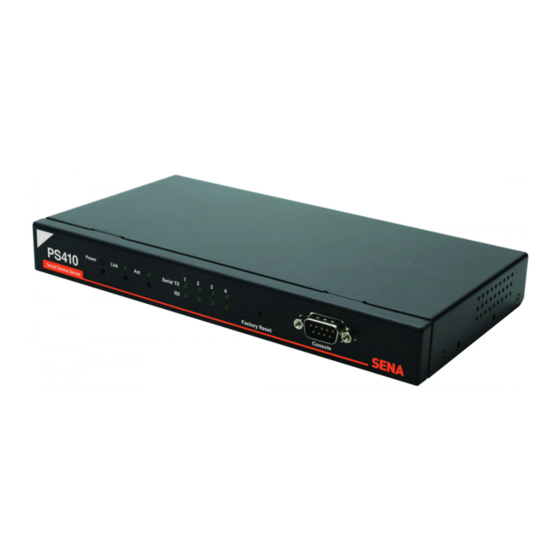
Figure 2-1 The panel layout of the PS110 2.1.2. PS410/810 Panel Layout The PS410/810 has three groups of LED indicator lamps to display the status, as shown in Figure 2-2 and Figure 2-3 (i.e. System, Ethernet and Serial ports). The first two lamps on the left side indicate Power, Ready(PS810 only). -
Page 14: Connecting The Hardware
Figure 2-2 The panel layout of the PS410 Figure 2-3 The panel layout of the PS810 2.2. Connecting The Hardware This section describes how to connect the Pro Series to your equipment for initial testing. - Connect the Pro Series to an Ethernet hub or switch - Connect the device - Connect the provided power source to the Pro Series 2.2.1. -
Page 15: Connecting To The Device
Figure 2-4 Connecting a network cable to the PS110 Figure 2-5 Connecting a network cable to the PS410 Figure 2-6 Connecting a network cable to the PS810 2.2.2. Connecting To The Device Connect the console cable to the Pro Series serial port. To connect to the console port of the device, the user needs to consider the type of console port provided by the device itself. - Page 16 And push the Data/Console switch to the Console side. And also please set the position of DIP switch for serial mode to RS-232 mode. Configuration of the PS110 is discussed on Section 2.2.5. Using The System Console.
-
Page 17: Connecting The Power
Connect the power cable to the Pro Series. If the power is properly supplied, the [Power] lamp will light up solid red. Figure 2-10 Connecting the power to the PS110 Figure 2-11 Connecting the power to the PS410 Figure 2-12 Connecting the power to the PS810... -
Page 18: Accessing The System Console
Connect one end of the console cable to the console port on the Pro Series. (For PS110, Push the Data/Console switch to the Console side. And also please set the position of DIP switch for serial mode to RS-232 mode. Configuration of DIP switch is discussed on Appendix 1. - Page 19 Figure 2-14 Connecting a system console cable to the PS410 Figure 2-15 Connecting a system console cable to the PS810 Connect the other end of the cable to the serial port of the user’s computer. Run a terminal emulator program (i.e. HyperTerminal). Set the serial configuration parameters of the terminal emulation program as follows: ...
- Page 20 Enter your username and password to log into the Pro Series. The factory default user settings are as follows. Login: root Password: root ProSeries login: root Password: After login, user can use various shell commands in the CLI(Command Line interface). For details on the CLI, refer to the chapter 7 CLI Guide.
-
Page 21: Using Remote Console
go to upper clear clear screen display path to current menu save save current configuration apply apply current configuration help display this exit exit ________________________________________________________________________________ COMMAND (Display HELP : help)>[Enter] _] / [________________________________________________________________________ 1. Network configuration 2. Serial port configuration 3. -
Page 22: Accessing The Web Browser Management Interface
Figure 2-17 Telnet program set up example (TeraTerm Pro) The user must log into the Pro Series. Type the user name and password. A factory default settings of the user name and password for CLI login are both root. After entering correct user name and password, user can see the CLI prompts. 2.3. - Page 23 Figure 2-18 Login screen of the Pro Series web management Figure 2-19 shows the configuration homepage of the Pro Series Web management interface. A menu bar is provided on the left side of the screen. The menu bar includes the uppermost configuration menu groups.
-
Page 24: Network Configuration
3. Network Configuration 3.1. IP Configuration The Pro Series requires a valid IP address to operate within the user’s network environment. If the IP address is not readily available, contact the system administrator to obtain a valid IP address for the Pro Series. -
Page 25: Using A Static Ip Address
3.1.1. Using A Static IP Address When using a Static IP address, the user must manually specify all the configuration parameters associated with the IP address of the Pro Series. These include the IP address, the network subnet mask, the gateway computer and the domain name server computers. This section will look at each of these in more detail. -
Page 26: Using Dhcp
the numeric IP addresses for a TCP/IP connection. The IP address of the DNS server must be able to access the host site with the provided domain name. The Pro Series provides the ability to configure the required IP addresses of both the Primary and Secondary DNS servers addresses. -
Page 27: Snmp Configurations
3.2. SNMP Configurations The Pro Series has the SNMP (Simple Network Management Protocol) agent supporting SNMP v1 and v2 protocols. Network managers like NMS or SNMP Browser can exchange information with Pro Series, as well as access required functionality. SNMP protocols include GET, SET, GET–Next, and TRAPs. With these functions, a manager can be notified of significant events (TRAPs), query a device for more information (GET), and make changes to the device state (SET). -
Page 28: Access Control Configuration
Indicates whether the SNMP agent process is permitted to generate system login traps for console, telnet and Web access. If users need support for adding or modifying MIBs, please contact Sena technical support. For more information about the MIBs and SNMP, see the RFCs 1066, 1067, 1098, 1317, 1318 and 1213. -
Page 29: Trap Receiver Configuration
3.2.3. Trap Receiver Configuration The Trap receiver defines managers, which can be notified of significant events (TRAP) from the Pro Series SNMP agent. 3.2.4. Management Using SNMP The Pro Series can be managed through the SNMP protocol using NMS (Network Management System) or SNMP Browser. -
Page 30: Dynamic Dns Configuration
Dynamic DNS Server regardless of any IP address change. By default, the Pro Series only supports Dynamic DNS service offered at Dynamic DNS Network Services, LLC (www.dyndns.org). Contact Sena technical support for issues regarding other Dynamic DNS service providers. -
Page 31: Smtp Configuration
Consequently, the email address set for the device can use an arbitrary username with a registered hostname (i.e. arbitrary_user@yahoo.com or anybody@sena.com). The SMTP user name and SMTP user password are required when either SMTP with authentication or POP-before-SMTP mode is selected. -
Page 32: Ip Filtering
Figure 3-6 SMTP mode selection in SMTP configuration 3.5. IP Filtering The Pro Series prevents unauthorized access using an IP address based filtering method. The users can allow one of the following scenarios by changing the parameter settings: - Any host cannot access a specific service of the Pro Series - Only one host of a specific IP address can access a specific service of the Pro Series - Hosts on a specific subnet can access a specific service of the Pro Series - Any host can access a specific service of the Pro Series... - Page 33 Service Service to which will be applied to the IP filtering rule. User can select one of Telnet, SSH, NFS, HTTP, HTTPS or each serial port. Chain rule Set the basic rule for the host to access the Pro Series as one of Accept, Drop or Reject. Figure 3-7 IP filtering Configuration The Pro Series provides a policy option.
-
Page 34: Syslog Server Configuration
Figure 3-9 IP filtering Configuration for each service and serial port Table 3-2 Input examples of Option and IP address/mask combination Input format Allowable Hosts Option IP address/mask Any host 0.0.0.0/0.0.0.0 Normal 192.168.1.120 192.168.1.120/255.255.255.255 Normal Any host except 192.168.1.120/255.255.255.255 Invert 192.168.1.120 192.168.1.1 ~ 192.168.1.0/255.255.255.0... -
Page 35: Locating Server
Figure 3-10 SYSLOG server configuration To receive log messages from the Pro Series, the SYSLOG server must be configured as “remote reception allowed”. If there is a firewall between the Pro Series and the SYSLOG server, there must be a rule that allows all outgoing and incoming UDP packets to travel across the firewall. The Pro Series supports SYSLOG facilities from local0 to local7. -
Page 36: Locating Server Communication Protocol
Note: Local ports: Each 2 byte data represent current local port setting of the corresponding serial port. Local ports data length of PS110 should be 2 bytes, while 8 bytes and 16 bytes for PS410 and PS810 respectively. Configured local TCP (or UDP) port numbers for each serial port are filled in the serial port number order base, (i.e. -
Page 37: Nfs Server Configuration
3.8. NFS Server Configuration The Pro Series supports NFS (Network File System) service for system or port data logging functions. To use this service, the user must specify the IP address of a NFS server and the mounting path on the NFS server. - Page 38 TCP keep-alive time: This represents the time interval between the last data transmission and keep-alive packet submissions by the Pro Series. These “keep-alive” messages are sent to the remote host to confirm that the session is still open. The default time value is 15 sec. ...
-
Page 39: Serial Port Configuration
4. Serial Port Configuration 4.1. Overview The serial port configuration capability allows the user to configure the host mode of each port, serial communication parameters, cryptography, port logging parameters and other related parameters. The serial port’s host mode can be set as any of the following: ... - Page 40 TCP Nagle algorithm Enable/Disable DTR option Allow incoming connection When DSR goes low When DSR goes high Port number Max allowed connection Inactivity timeout (0 for unlimited) Socket ID (for outgoing connection) Accept unlisted Send unlisted DTR option DSR behavior DTR option DSR behavior Phone number to host address mapping...
-
Page 41: Serial Port Configuration
SNMP trap receiver’s IP address SNMP trap community SNMP trap version Add/Edit an event keyword Event keyword Email notification SNMP trap notification Port command Remove a keyword Figure 4-1 shows the web-based serial port configuration screen. This serial port configuration main screen summarizes port information. -
Page 42: Port Title
Figure 4-2 Serial port enable/disable 4.2.2. Port Title Users can enter descriptive information for each port based on the device attached to it. This can include the device type, vendor, and/or location. Figure 4-3 Port title configuration 4.2.3. Host Mode Configuration The Pro Series operating mode is called the “host mode”. - Page 43 UDP mode The UDP mode operation is similar to that of TCP mode except that it utilizes UDP protocol. Modem emulation mode Select this mode when the serial device already supports modem AT commands or users want to perform the session control by using AT commands.
- Page 44 It represents “a waiting for a connection request from any registered remote host”. It is a default start- up mode when it is set as TCP mode. [Closed] It means “no connection state”. If the data transfer between a remote host and the Pro Series is completed, the state is changed to this state as a result that either of the remote host or the Pro Series sent a disconnection request.
- Page 45 2) Operations Serial data transfer Whenever the serial device sends data through the serial port of the Pro Series, data will be accumulated on the serial port buffer of the Pro Series. If the buffer is full or the time gap reaches the inter-character timeout (See Options in section 4.2.6.
- Page 46 For this purpose, SENA OEM version of Serial/IP from Tactical Software, LLC is bundled with Pro Series. Please refer to documentations of Serial/IP for more detail information about using the COM port redirector. (Please refer to section Appendix 5. Using Pro Series With Serial/IP for more detail information) ...
- Page 47 protecting the Internet against excessive packet loads. However, some applications suffer performance problems as a result of the traditional implementation of the Nagle algorithm.(An interaction between the Nagle algorithm and TCP’s delayed acknowledgement policy can create especially severe problems, through a temporary “deadlock.”) TCP Nagle algorithm can be disabled or enabled through this option.
- Page 48 TCP connection request rejected Or internal TCP time-out Sync-Sent In-coming TCP Close request TCP connection request accepted Inactivity time-out Incoming data via serial port Data Established Incoming data Closed from remote host Accept Reject Listen Sync-Recvd Incoming TCP connection request Incoming data via serial port Figure 4-5 State Transition Diagram of TCP mode 4.2.3.2.
- Page 49 Figure 4-6 Host mode configuration (UDP mode) 1) Operations If a remote host sends a UDP datagram to the one of UDP Local port of the Pro Series, Pro Series first checks whether it is from one of the hosts configured on remote host configuration. If the remote host is one of the hosts configured on remote host configuration, then Pro Series transfers the data through the serial port.
- Page 50 Inactivity Timeout In UDP mode, Inactivity Timeout is used in maintaining recent unlisted remote host. If there is no data transmission between unlisted remote host and serial port of Pro Series during Inactivity Timeout, Pro Series will not send data from a serial port to the recent unlisted remote host again. Namely, Inactivity Timeout in UDP mode is the time maintained recent unlisted remote host list by Pro Series.
- Page 51 the remote host, which has connected Pro Series recently. Recent unlisted remote host is a remote host, which has accessed a corresponding serial port of Pro Series but is not configured on remote host configuration. Surely, Pro Series also send data to the hosts, which are configured on remote host configuration.
- Page 52 [remote IP][remote port] (Port Number is permitted from 1 to 65534) CONNECT [CR][LF] [CR][LF] e.g. atdtps.sena.com:1002 Connect to domain address ps.sena.com, port 1002 If failure in connection, NO CARRIER [CR][LF] ATDR This command is similar to ATD(T). The difference is that...
- Page 53 I, I0 : display “Sena Technologies, Inc.” ATIn [CR][LF] I3 : display model number <= Others : display “OK” ERROR [CR][LF] Set inactivity timer to n minutes AT\Tn [CR][LF] \T, \T0: inactivity timer disabled (default) OK [CR][LF] ATBn, ATCn, ATLn, ATMn, ATNn, ATP, ATT, ATYn, AT%Cn, AT%En, AT&Bn,...
- Page 54 Table 4-4 Default value of S-Registers Index Default Value Index Default Value Index Default Value 0 ~ 1 13 ~ 24 26 ~ 37 39 ~ 99 Figure 4-7 Typical case of command/data flow of modem emulation mode In modem emulation mode, user can also set specific phone number to host address/port mapping table.
- Page 55 The DTR option can be set to one of three options: Always HIGH: The state of the DTR pin is maintained high. Always LOW: The state of the DTR pin is maintained low. High when TCP/UDP is opened: The state of the DTR pin will be maintained high if the UDP connection is established.
- Page 56 Default command echo User can disable or enable echo of AT command that is entered by user in this menu. (Same functionality to ATEn command) Default data mode User can select the TCP data mode between Raw TCP mode and Telnet binary mode. The Raw TCP means that there is no application protocol over the TCP protocol.
-
Page 57: Remote Host Configuration
4.2.4. Remote Host Configuration Remote host configuration is the list of hosts that will receive data from serial port of Pro Series when there is data transmission from the serial port of the Pro Series. In TCP mode, user can also configure secondary remote host (Backup host) that will receive data from serial port if Pro Series fails to connect to primary remote host. -
Page 58: Cryptography Configuration
4.2.5. Cryptography Configuration The Pro Series supports encrypted sessions for only the TCP mode including modem emulation mode (not UDP mode). Figure 4-10 Cryptography configuration 4.2.5.1. Secure Sockets Layer(SSL) Cryptography Method By setting the cryptography method as SSL, the Pro Series can communicate with another device supporting SSLv3 cryptography method during encrypted sessions. - Page 59 To initiate SSL sessions, exchange of messages called the SSL handshake is required between two devices (Server and Client). The SSL protocol uses a combination of public-key and symmetric key encryption. Symmetric key encryption is much faster than public-key encryption, but public-key encryption provides better authentication techniques.
- Page 60 be encrypted with the session key. It then sends a separate (encrypted) message indicating that the client portion of the handshake is finished. 9. The server sends a message to the client informing it that future messages from the server will be encrypted with the session key.
- Page 61 In RC4 cryptography mode, the Pro Series encrypt and decrypt all TCP streams using a Key string. The Pro Series can communicate with another device or another Pro Series that supports RC4 cryptography mode with same Key string. For the sample application programs of SSL/RC4 cryptography method, please contact the Sena Technical support.
-
Page 62: Serial Port Parameters
RS232 mode, RS422(RS485 full) mode or RS485 half mode. User can set the serial communication type by using DIP switch near by serial port in case of PS110/410. To change the serial communication type, change the position of each DIP switch as shown on Figure 4-14. For PS810, user can change the serial communication type of each serial port using configuration menu as shown on Figure 4-17. - Page 63 PS110/410. Changing the position of DIP switch while the power is on may cause damage to the device. (If the DIP switches are set incorrectly, the PS110/410 will display “Invalid” for the UART type on the UI as shown on Figure 4-15, which will hinder communications to the serial port.) 2.
- Page 64 10 bits and the time required to transfer one character is 10 (bits) / 1200 (bits/s) * 1000 (ms/s) = 8.3 ms. Therefore, you have to set inter-character timeout to be larger than 8.3 ms. The inter-character timeout is specified in milliseconds. Figure 4-16 Serial parameter configuration (PS110/410)
-
Page 65: Modem Configuration
Figure 4-17 Serial parameter configuration (PS810) 4.2.7. Modem Configuration The Pro Series supports direct modem connection to the serial port. When user wants to connect to a modem on its serial port, he must configure Modem init-string and DCD behavior on the modem configuration page. - Page 66 Automatic release modem connection If Automatic release modem connection is set as Enable, modem connection will be closed by Pro Series if all TCP connections are closed. If this option is set as Disable, modem connection will not be closed by Pro Series even if all TCP connections are closed.
-
Page 67: Port Logging
4.2.8. Port Logging With the port logging feature, the data sent through the serial port is stored to MEMORY or a mounting point on an NFS server. Enable/disable port logging This parameter defines whether to enable or disable the port-logging feature. The factory default setting is [disabled]. -
Page 68: Port Event Handling Configurations
4.2.9. Port Event Handling Configurations The Pro Series provides a user for a means of monitoring or reacting to data from serial device attached to a serial port of it through Port event handling configuration. Namely, user can define keywords for each serial port that will trigger the email/SNMP notification or command sent to the serial port directly on Port event handling configuration. - Page 69 detected. SNMP trap notification This parameter enables or disables SNMP trap notification feature of Pro Series. Subject of SNMP trap This parameter set the subject of SNMP trap that will be sent by Pro Series when pre-defined keyword is detected.
-
Page 70: Copy Port Configuration
Figure 4-20 Port event-handling configurations 4.2.10. Copy Port Configuration User can copy port configuration of one port to another. There are two methods in copying port configuration. One is “Copy current port configuration to” specified ports and another is “Copy current port configuration from”... -
Page 71: System Administration
5. System Administration The Pro Series displays the system status and the log data via a Status Display Screen. This screen is used for management purposes. System status data includes the model name, serial number, firmware version and the network configuration of the Pro Series. The Pro Series can also be configured to deliver log data automatically via email to a specified recipient with the system-logging feature. -
Page 72: Change Password
server or the SYSLOG server. If the internal memory is used to store system log data, the log data will be cleared when the Pro Series is turned off. To preserve the system log data, set the storage location to be SYSLOG server or NFS server. To do this, the user must configure the corresponding media in advance. -
Page 73: Device Name Configuration
The Pro Series maintains current date and time information. The PS410/810’s clock and calendar settings are backed up by internal battery power. (Please note that PS110 does not have a battery for internal clock. Current date and time setting will not be retained after system rebooting. So it is recommended to use NTP server to maintain correct date and time in PS110 model) The user can change the current date and time, as shown in Figure 5-5. -
Page 74: Factory Reset
Figure 5-6 NTP configuration 5.6. Factory Reset The user may restore the factory default settings at any time using this menu. (User can also restore the factory default settings using the reset switch near by serial console port.) Figure 5-7 Factory Reset 5.7. - Page 75 Figure 5-8 Configuration Management To export the current configurations, follow this: 1. Select the encrypting option 2. Type the file name. 3. Click the [Export] button. To import the exported configurations, follow this: 1. Select the location to import from. 2.
-
Page 76: Firmware Upgrade
5.8. Firmware Upgrade Firmware upgrades are available via serial, remote console or web interface. The latest upgrades are available on the Sena web site at http://www.sena.com/support/downloads/. Figure 5-9 shows the firmware upgrade web interface. Figure 5-9 Firmware upgrade To upgrade firmware via the web: 1. - Page 77 3. System administration ________________________________________________________________________________ COMMAND (Display HELP : help)>3 _] System administration [____________________________________________________ 1. System status 2. System logging 3. Device Name : PS110 4. Date and time 5. Change password 6. User Administration 7. Factory reset 8. Firmware upgrade ________________________________________________________________________________ COMMAND (Display HELP : help)>8...
-
Page 78: User Administration
_] Firmware upgrade [_________________________________________________________ Do you want to upgrade firmware? [yes/no] yes Transfer firmware by zmodem using your terminal application. To escape, press Ctrl+X **B0ff000005b157 **B0ff000005b157 **B0ff000005b157 **B0ff000005b157 Firmware upgrade failed ! Now reboot ... Figure 5-12 Firmware upgrade failure message 5.9. - Page 79 Figure 5-14 Port user configuration...
-
Page 80: System Statistics
6. System Statistics The Pro Series Web interface provides system statistics menus. The user can use these menus to access statistical data and tables stored in the Pro Series memory. Network interfaces statistics and serial ports statistics display statistical usage of the link layer, lo, eth and serial ports. IP, ICMP, TCP and UDP statistics display usages of four primary components in the TCP/IP protocol suite. -
Page 81: Serial Ports Statistics
6.2. Serial Ports Statistics Serial ports statistics displays the usage history of 32 serial ports, baud rate configurations and each port’s pin status. ( : On : Off ) Figure 6-2 Serial ports status 6.3. IP Statistics The IP Statistics screen provides statistical information about packets/connections using an IP protocol. - Page 82 ForwDatagrams : Specifies the number of datagrams forwarded. InUnknownProtos : Specifies the number of locally addressed datagrams received successfully but discarded because of an unknown or unsupported protocol. InDiscard : Specifies the number of input IP datagrams for which no problems were encountered to prevent their continued processing, but which were discarded (for example, for lack of buffer space).
- Page 83 ReasmOKs : Specifies the number of datagrams that were successfully reassembled. ReasmFails : Specifies the number of datagrams that cannot be reassembled. FragOKs : Specifies the number of datagrams that were fragmented successfully. FragFails : Specifies the number of datagrams that needs to be fragmented but couldn’t be because the IP header specifies no fragmentation.
-
Page 84: Icmp Statistics
6.4. ICMP Statistics The ICMP Statistics screen provides statistical information about packets/connections using an ICMP protocol. Definitions and descriptions of each parameter are described below: Figure 6-4 ICMP statistics InMsgs, OutMsgs : Specifies the number of messages received or sent. ... - Page 85 InTimeExcds, OutTimeExcds : Specifies the number of time-to-live (TTL) exceeded messages received or sent. A time-to-live exceeded message is sent to the originating computer when a datagram is discarded because the number of routers it has passed through exceeds its time-to-live value. ...
-
Page 86: Tcp Statistics
InAddrMaskReps, OutAddrMaskReps : Specifies the number of address mask responses received or sent. A computer sends an address mask response in response to an address mask request. 6.5. TCP Statistics The TCP Statistics screen provides statistical information about packets/connections using a TCP protocol. - Page 87 EstabResets : Specifies the number of established connections that have been reset. CurrEstab : Specifies the number of currently established connections. InSegs : Specifies the number of segments received. OutSegs : Specifies the number of segments transmitted. This number does not include retransmitted segments. ...
-
Page 88: Udp Statistics
6.6. UDP Statistics The UDP Statistics screen provides statistical information about packets/connections using a UDP protocol. Definitions and descriptions of each parameter are described below: InDatagrams : Specifies the number of datagrams received. NoPorts : Specifies the number of received datagrams that were discarded because the specified port was invalid. -
Page 89: Cli Guide
7. CLI Guide 7.1. Introduction The root user can access the Linux console command line interface (CLI) of the Pro Series via the serial console or TELENT/SSH. In the CLI, the user can perform standard Linux commands to view the status of the Pro Series, edit the configuration, apply configuration changes. 7.2. -
Page 90: Accessing Cli
7.4. Accessing CLI Serial console: 1) Connect the console port of the Pro Series with the PC serial port 2) Run a PC terminal emulation program 3) Configure the PC serial port to: 9600-8-N-1 No flow control 4) Press <enter> 5) Login with the Pro Series root account Telnet console: 1) telnet Pro_Series_ip_address... -
Page 91: Appendix 1. Connections
White with brown Brown A 1.2. Console And Serial Port Pinouts The pin assignment of the PS110/PS410/PS810 DB9 connector is summarized in Table A-2. Each pin has a function according to the serial communication type configuration. 1 2 3 4 5... -
Page 92: A 1.3. Ethernet Wiring Diagram
The serial communication type can be set by DIP switch near by serial port. (Only for PS110 and PS410) To change the serial communication type, change the position of each DIP switch as shown below. But please note that the power of the Pro Series should be turned off before changing the serial communication type. -
Page 93: A 1.4. Serial Wiring Diagram
A 1.4. Serial Wiring Diagram A 1.4.1. RS232 Serial Wiring Diagram HelloDevice Serial Device Tx(3) Rx(2) RTS(7) CTS(8) DTR(4) DSR(6) GND(5) RS232 Figure A-6 RS232 wiring diagram A 1.4.2. RS422/485 Serial Wiring Diagram *Data+ means that coupling of Tx+(1) pin and Rx+(2) pin *Data- means that coupling of Tx-(6) pin and Rx-(8) pin Figure A-7 RS485 wiring diagram... - Page 94 * Termination Resistor at Tx side can be omitted if the signal status is good. Figure A-8 RS422 wiring diagram...
-
Page 95: Appendix 2. Pro Series Configuration Files
Appendix 2. Pro Series Configuration files A 2.1. port1.conf /serial/*1/parameter/baudrate=9600 /serial/*1/parameter/databit=0 /serial/*1/parameter/stopbit=0 /serial/*1/parameter/parity=0 /serial/*1/parameter/flowcontrol=0 /serial/*1/parameter/interchar_to=0 /serial/*1/parameter/dtr_option=0 /serial/*1/parameter/dsr_option=0 /serial/*1/modem/modem_init_string=q1e0s0=2 /serial/*1/modem/modem_dcd_option=0 /serial/*1/modem/modem_auto_disconnection_enable=0 /serial/*1/modem/modem_enable=0 /serial/*1/event/event_email_enable=0 /serial/*1/event/event_snmp_enable=0 /serial/*1/event/event_notification_interval=30 /serial/*1/event/event_enable=0 /serial/*1/hostmode/accept_unlisted=1 /serial/*1/hostmode/send_unlisted=1 /serial/*1/enable=1 /serial/*1/title=Port #1 /serial/*1/hostmode/mode=0 /serial/*1/hostmode/port=7001 /serial/*1/hostmode/userauth=0 /serial/*1/hostmode/telnet=0 /serial/*1/hostmode/max_connection=8 /serial/*1/hostmode/cyclic_time=0 /serial/*1/hostmode/inactive_time=0 A 2.2. filter.conf /network/filter/specification/telnet=1 /network/filter/specification/ssh=1 /network/filter/specification/http=1... - Page 96 /network/snmp/nms/*4=0.0.0.0 public 0 /network/snmp/trap/*1=0.0.0.0 public 0 /network/snmp/trap/*2=0.0.0.0 public 0 /network/snmp/trap/*3=0.0.0.0 public 0 /network/snmp/trap/*4=0.0.0.0 public 0...
-
Page 97: Appendix 3. Well-Known Port Numbers
Appendix 3. Well-known Port Numbers Port numbers are divided into three ranges: Well Known Ports, Registered Ports, and Dynamic and/or Private Ports. Well Known Ports are those from 0 through 1023. Registered Ports are those from 1024 through 49151. Dynamic and/or Private Ports are those from 49152 through 65535. Well Known Ports are assigned by IANA, and on most systems, can only be used by system processes or by programs executed by privileged users. -
Page 98: Appendix 4. Guide To The Bios Menu Program
Pro Series unit is powered up, the user will enter the bios menu program. From this menu program, the user can set various system parameters, test system hardware, and perform firmware upgrades. Note: For PS110, the bios menu will be displayed only when the Data/Console switch is located at the Console side. A 4.2. Main Menu... -
Page 99: A 4.4. Hardware Test Menu
<ESC> Back, <ENTER> Refresh ----->1 Enter Current Data(mm/dd/yy) : 05/20/05 Press the ENTER key to continue!! ----------------------------------------------------------------------------- RTC Configuration ----------------------------------------------------------------------------- Select Menu 1. Data(mm/dd/yy) : 05/20/05 2. Time(hh:mm:ss) : 15:02:41 <ESC> Back, <ENTER> Refresh ----->2 Enter Current Data(hh:mm:ss) : 15:03:40 Press the ENTER key to continue!! ----------------------------------------------------------------------------- RTC Configuration... - Page 100 1. Auto test 2. DRAM test 3. FLASH test 4. EEPROM test 5. Ethernet test 6. UART Mode test <ESC> Back, <ENTER> Refresh -----> 0 ----------------------------------------------------------------------------- Hardware Test ----------------------------------------------------------------------------- Select menu 0. Test Mode - Looping(Without External test in Auto Test) 1.
- Page 101 (Read/WRite)------------------[ SUCCESS] Port # 2 test in progressing(MODE)------------------------[ RS232] (Read/WRite)------------------[ SUCCESS] Port # 3 test in progressing(MODE)------------------------[ RS232] (Read/WRite)------------------[ SUCCESS] Port # 4 test in progressing(MODE)------------------------[ RS232] (Read/WRite)------------------[ SUCCESS] <--External Uart Test--> Port # 1 test in progressing(MODE)------------------------[ RS232] (Read/WRite)------------------[ SUCCESS] (RTS/CTS)---------------------[ SUCCESS] (DTR/DSR)---------------------[ SUCCESS] Port # 2 test in progressing(MODE)------------------------[...
-
Page 102: A 4.5. Firmware Upgrade Menu
******* Hardware auto-detect and auto-test ******* [DRAM] DRAM Test ---------------------------------------------[SKIPPED] [FLASH] FLASH Test ---------------------------------------------[SKIPPED] Figure A-13 Skip the specific test using ESC key A 4.5. Firmware Upgrade Menu By using the ‘Firmware upgrade’ menu, the user can upgrade the firmware of the unit. Before firmware upgrade, the user can check the current firmware version by selecting menu item 3 from the Main menu page The firmware upgrade menu supports only the TFTP protocol for remote firmware... - Page 103 TFTP Boot image(ps110a.img) loading at 0xb00000.. 3019495 Bytes 3019495 bytes receive done. kernel upgrade start. Kernel Block : Write to Flash... done kernel upgrade complete. Cramfs upgrade start. Cramfs Block : Write to Flash... done Cramfs upgrade complete. Configuration upgrade start. Configuration Block : Write to Flash...
-
Page 104: Appendix 5. Using Pro Series With Serial/Ip
Appendix 5. Using Pro Series With Serial/IP A 5.1. Pro Series vs. Serial/IP Options Table A-4 Pro Series vs. Serial/IP option compatibility matrix table Serial Port Configuration of Pro Series Serial/IP Configuration Cryptography Host mode Configuration Connection Configuration Credentials Security Protocol Host mode Telnet Protocol... - Page 105 Figure A-16 Host mode configuration Step 2. Set Cryptography configuration of serial port #1 of Pro Series as follows, SSL enable = Enable Figure A-17 Cryptography configuration...
- Page 106 Step 3. Open Serial/IP Control Panel and check the COM port you want to use to communicate with serial port #1 of Pro Series by pressing “Select Ports” button. Figure A-18 Select Ports on Serial/IP Control Panel Step 4. Enter IP address of Server (IP address of Pro Series) and Port number (port number of serial port #1) correctly and then select other parameters as follows.
- Page 107 Figure A-19 Set parameters on Serial/IP Control Panel Step 5. Open the terminal emulation program and select the corresponding COM port. Then user can use the serial port of Pro series using his local terminal emulation program as if it is one of COM ports on his PC.
- Page 108 Figure A-20 Connect to serial port of Pro series via Serial/IP Step 6. User can monitor or trace the connection status using Serial/IP Port Monitor or Trace window. Figure A-21 Serial/IP Trace Window...
-
Page 109: Appendix 6. Warranty
(a) any misapplication or misuse of the Product; (b) failure of Customer to adhere to any of SENA’s specifications or instructions; (c) neglect of, abuse of, or accident to, the Product; or (d) any associated or complementary equipment or software not furnished by SENA. -
Page 110: A 6.3. Hardware Product Warranty Details
Product will be furnished on an exchange basis and will be either reconditioned or new. All replaced Product and parts become the property of SENA. If SENA determines that the Product is not under warranty, it will, at the Customers option, repair the Product using current SENA standard rates for parts and labor, and return the Product at no charge in or out of warranty.
Need help?
Do you have a question about the PS110 and is the answer not in the manual?
Questions and answers