Table of Contents
Advertisement
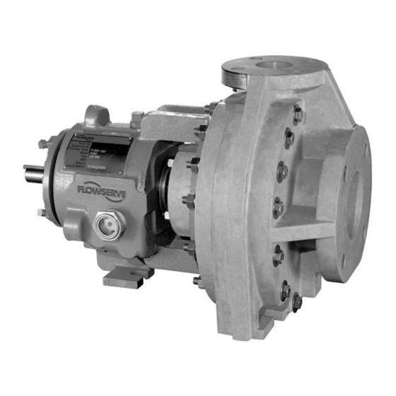
PolyChem GRP
ANSI B73.5M standard horizontal and self-priming
non-metallic, frame-mounted pump
PCN=71569132 12-04A (E). Original instructions.
These instructions must be read prior to installing,
operating, using and maintaining this equipment.
Компания ПромХимТех-
официальный дистрибьютор
насосов Flowserve
www.promhimtech.ru
Тел. 8 800 250-01-54
e-mail: zakaz@promhimtech.ru
USER INSTRUCTIONS
Installation
Operation
Maintenance
Advertisement
Table of Contents

Related Manuals for Flowserve PolyChem GRP Series


Summary of Contents for Flowserve PolyChem GRP Series
- Page 1 Компания ПромХимТех- официальный дистрибьютор насосов Flowserve www.promhimtech.ru Тел. 8 800 250-01-54 e-mail: zakaz@promhimtech.ru USER INSTRUCTIONS Installation PolyChem GRP Operation Maintenance ANSI B73.5M standard horizontal and self-priming non-metallic, frame-mounted pump PCN=71569132 12-04A (E). Original instructions. These instructions must be read prior to installing,...
-
Page 2: Table Of Contents
5.5 Guarding ............. 27 5.6 Priming and auxiliary supplies ...... 28 5.7 Starting the pump ........29 5.8 Running or operation ........29 5.9 Stopping and shutdown ....... 30 5.10 Hydraulic, mechanical and electrical duty ... 30 flowserve.com Page 2 of 52... - Page 3 Part assemblies (4.2) ..........13 Parts lists (see 8) ........... 48 Performance (3.4) ..........12 Piping (4.6) ............17 Pre-commissioning (5.1) ........24 Priming and auxiliary supplies (5.6) ......28 Protection systems (4.9) ........23 flowserve.com Page 3 of 52...
-
Page 4: Introduction And Safety
Damage or failure caused activity with operations personnel, and follow all plant by misuse is not covered by the Flowserve warranty. safety requirements and applicable safety and health In addition, any modification of Flowserve products or laws and regulations. -
Page 5: Safety
Flowserve before start up. laws and regulations. 1.6.3 Safety action 1.6 Safety... - Page 6 See section 3 for pressure versus temperature ratings based on the material of construction. Where Flowserve has supplied only the bare shaft pump, the Ex rating applies only to the pump. The party NEVER OPERATE THE PUMP WITH...
- Page 7 40 ºC (104 ºF); refer to Ensure the pump and relevant suction and discharge Flowserve for higher ambient temperatures. pipeline system is totally filled with liquid at all times during the pump operation so that an explosive The surface temperature on the pump is influenced atmosphere is prevented.
-
Page 8: Nameplate And Safety Labels
Where there is a risk from such tools or materials, maintenance must be conducted in a safe area. It is recommended that a maintenance plan and schedule is adopted. (See section 6, Maintenance.) flowserve.com Page 8 of 52... -
Page 9: Specific Machine Performance
This is typically 80 to 85 dBA. driver obtained from the supplier. Consult Flowserve or a noise specialist if assistance is required in The usual approach is to control the exposure time to combining the values. -
Page 10: Transport And Storage
Any shortage and/or damage must support ribs between the housing barrel and the be reported immediately to Flowserve Pump Division casing attachment flange. Use a choker hitch when and must be received in writing within one month of slinging. -
Page 11: Recycling And End Of Product Life
Long term storage is defined as more than six months, but less than 12 months. The procedure 3.2 Name nomenclature Flowserve follows for long term storage of pumps is The pump size will be engraved on the nameplate given below. These procedures are in addition to the typically as below: short term procedure. -
Page 12: Design Of Major Parts
The mechanical seal(s), attached to the pump shaft, (-20 °F) (150 °F) (225 °F) seals the pumped liquid from the environment. Gland 1K3x2GS-7 9.31 (135) 9.31 (135) 9.31 (135) packing may be fitted as an option. flowserve.com Page 12 of 52... -
Page 13: Installation
The following data are typical, and factors such as liquid being pumped, temperature, and seal type may influence them. If required, a definitive statement for your application can be obtained from Flowserve. 3.4.2 Minimum continuous flow The minimum continuous flow (MCF) is based on a percentage of the best efficiency point (BEP). - Page 14 For washer (item 3) first then tighten the other nuts. example, mounting surface flatness of 0.17 mm/m (0.002 in./ft) is offered on the Flowserve Type E “Ten Point” baseplate shown in figure 4-1. 1. Stilt bolt ...
-
Page 15: Grouting
25 mm (1 in.), and lock the nuts in place. k) It should be noted that the connecting pipelines must be individually supported, and that the spring mounted baseplate is not intended to support total static pipe loads. Figure 4-5 flowserve.com Page 15 of 52... -
Page 16: Initial Alignment
Flowserve’s Thus the factory alignment will be done with the base factory preliminary alignment procedure as sitting in an unrestrained condition on a flat and level described in section 4.5, and then continue with... -
Page 17: Piping
Ensure that these connection. Never use pipe or fittings on the suction covers are removed from the pump before connecting that are smaller in diameter than the pump suction size. any pipes. flowserve.com Page 17 of 52... - Page 18 10 pipe diameters between the pumps (ASME B73.5) source and the pump suction. In most cases, Flowserve chemical process pumps meet or exceed horizontal reducers should be eccentric and mounted the allowable nozzle loads given by ANSI/HI 9.6.2.
- Page 19 4-15 movement Combined axis B movement Note: All of the above equations are found by dividing the applied piping loads by the adjusted figure values flowserve.com Page 19 of 52...
- Page 20 When the pump is intended to be equipped with a representative for the proper connections. mechanical seal, it is Flowserve standard practice to install the mechanical seal in the pump prior to When installing piping, do not install metal pipe shipment.
- Page 21 6 672 17 792 -15 568 -2 034 6 780 -5 424 Group 3 (3 500) (-2 000) (1 500) (4 100) (-4 000) (1 500) (4 000) (-3 500) (-1 500) (5 000) (-4 000) flowserve.com Page 21 of 52...
- Page 22 4.6.6.2 Packing When the pump is intended to be equipped with shaft packing, it is not Flowserve standard practice to install the packing in the stuffing box prior to shipment. The packing is shipped with the pump. It is the pump installer’s responsibility to install the...
-
Page 23: Electrical Connections
4.5. This ensures there will potentially explosive area or is handling a hazardous be sufficient clearance between the motor hold liquid. If in any doubt consult Flowserve. down bolts and motor foot holes to move the motor into final alignment. The pump and driver If there is any possibility of the system allowing the should be within 0.38 mm (0.015 in.) FIM (Full... -
Page 24: Commissioning, Start-Up, Operation And Shutdown
During the lubricated by Flowserve. Before operating the pump, initial operating period monitor the bearing housing fill the bearing housing to the center of the oil sight operating temperature. - Page 25 18 months 18 months 18 months 80 - 94 °C (175 - 200 °F) * Assuming good maintenance and operation practices, and no contamination. ** May be increased to 36 months with ANSI 3A™ power end. flowserve.com Page 25 of 52...
-
Page 26: Impeller Clearance
The amount of grease required for horizontal pumps GRP is set off the casing to achieve the final is shown in figure 5-10. operational gap. The impeller clearance was set at the factory. (See figure 5-11.) flowserve.com Page 26 of 52... -
Page 27: Direction Of Rotation
(Note that only one side of the guard needs to be 3J12 x 10 x 15 17.45 mm (0.687 in) 4J12 x 10 x 15B 17.45 mm (0.687 in) removed.) To reassemble simply reverse the above procedure. flowserve.com Page 27 of 52... -
Page 28: Priming And Auxiliary Supplies
Note - if motor diameter is smaller than the guard diameter, trim guard so that it extends over the Flowserve offers as an option a ClearGuard™ which end of the motor as far as possible. allows you to see the condition of the coupling. (See e) Deburr the trimmed end with a file or a sharp knife. -
Page 29: Starting The Pump
Do not operate the pump below dangerous condition inside the pump casing. minimum thermal flow, as this could cause an excessive temperature rise. Contact a Flowserve Sales Engineer When in service, pumps using inlet pipes with foot for determination of minimum thermal flow. -
Page 30: Stopping And Shutdown
100 ºC (212 ºF) for oil lubrication how to evaluate the implications of any change. If in and 105 ºC (220 ºF) for grease lubrication. doubt contact your nearest Flowserve office. flowserve.com Page 30 of 52... -
Page 31: Maintenance
It is important that 6.1 General checks are made with your nearest Flowserve office if changes in viscosity are planned. It is the plant operator's responsibility to ensure that all maintenance, inspection and assembly work 5.10.3 Pump speed... -
Page 32: Maintenance Schedule
Refer to section 7, Faults; causes and remedies, 6.3.1 Ordering of spares for fault diagnosis. Flowserve keeps records of all pumps that have been b) Ensure equipment complies with the supplied. Spare parts can be ordered from your local recommendations in this manual. -
Page 33: Recommended Spares And Consumable Items
Bearing pullers replacement parts to the original design specification Bearing induction heater should be obtained from Flowserve. Any change to Dial test indicator the original design specification (modification or use Flowserve Mark 3 tool kit. (See 6.1 below.) of a non-standard part) will invalidate the pump’s... -
Page 34: Setting Impeller Clearance
Tighten the impeller with the impeller wrench from the Flowserve Mark 3 tool kit. To do this, grasp the impeller in both hands and, with the impeller wrench handle to the left (viewed from the impeller end of the... -
Page 35: Disassembly
Threaded impellers. (See figure 6-7 and 6-8.) Use a shaft key [6700] and mount the impeller wrench 6.8.1 Power end removal from the Flowserve Mark 3 tool kit (figure a) Before performing any maintenance, disconnect the 6-1) to the end of the shaft. With the wrench handle driver from its power supply and lock it off line. - Page 36 Then pull the gland [4120] and stationary seat off The bearing carrier assembly with the shaft and the shaft. Remove the stationary seat from the bearings should come free. gland. Discard all O-rings and gaskets. flowserve.com Page 36 of 52...
- Page 37 The Mark 3A design has an optional oil slinger [2541] located between the bearings. If present, inspect it for damage or looseness. Remove if it Figure 6-18 needs to be replaced. flowserve.com Page 37 of 52...
-
Page 38: Examination Of Parts
2) The ASME B73.5M standard does not specify a recommended the following pages. level of alignment. Flowserve recommends that the pump and motor shafts be aligned to within 0.05 mm (0.002 in.) parallel FIM 6.9.4 Additional parameters checked by (full indicator movement) and 0.0005 mm/mm (0.0005 in./in.) - Page 39 To minimize shaft whip it is imperative that the impeller is balanced. All impellers manufactured by Flowserve are balanced after they are trimmed. If for any reason, a customer trims an impeller, it must be re-balanced. See note 1 under figure 6-19 regarding acceptance criteria.
-
Page 40: Assembly Of Pump And Seal
MTBPM. By using Shaft movement caused by pipe strain this tool Flowserve can often determine not only the Pipe strain is any force put on the pump casing by the existence of a problem before it becomes serious, but piping. - Page 41 1) These bearings are open on both sides. They are lubricated by oil bath or oil mist. 2) These bearings are pre-greased by Flowserve. Replacement bearings will generally not be pre-greased, so grease must be applied by the user. They have a single shield, which is located on the side next to the grease buffer, or reservoir. The bearings draw grease from the reservoir as it is needed.
- Page 42 SKF’s designation is “BECB”. regarding the VBXX Inpro seal. Follow the NTN’s designation is “G”. instructions provided with the seal by the manufacturer. A special shaft is required when using duplex angular contact bearings.) flowserve.com Page 42 of 52...
- Page 43 Install the set bolts [6570.4] and lockwashers [6541.3] and screws [6570.3] loosely. torque up to 20 Nm (15 lbf•ft). (For 2K3x1.5G-10, 2K4x3G-10 and 2K6x4G-10 units use eccentric washers and nuts instead.) flowserve.com Page 43 of 52...
- Page 44 A typical machining setup machined down to the correct size. It is preferred to would be as described below. send the impeller to your Flowserve representative Start machining across the outer diameter. for machining, but when this is not possible, the Machine from both sides to the middle.
-
Page 45: Faults; Causes And Remedies
7 FAULTS; CAUSES AND REMEDIES Troubleshooting The following is a guide to troubleshooting problems with Flowserve Mark 3 pumps. Common problems are analyzed and solutions offered. Obviously, it is impossible to cover every possible scenario. If a problem exists that is not covered by one of the examples then refer to one of the books listed in section 10.3, Sources of additional information, or contact a Flowserve Sales Engineer or Distributor/Representative for assistance. - Page 46 Page 46 of 52...
- Page 47 3. A brown or bluish discoloration of the which it can rid itself of excessive lubricant, otherwise the bearing races. bearing may overheat and fail prematurely. 3. Be sure the proper grade of lubricant is used. flowserve.com Page 47 of 52...
-
Page 48: Parts Lists And Drawings
Sight gage – bearing housing 3856 Hexnut – casing 6580.3 Gland – clamped seat 4120 Key – drive shaft 6700 4200 Mechanical seal Oil seal – inboard 4310.1 Oil seal – outboard 4310.2 Gasket – cover (nose) 4590.1 flowserve.com Page 48 of 52... -
Page 49: Polychem Grp Pump, Group 2
Hexnut – gland 6580.2 Gland – clamped seat 4120 Hexnut – casing 6580.3 4200 Mechanical seal Key – drive shaft 6700 Oil seal – inboard 4310.1 Oil seal –outboard 4310.2 Gasket – cover (nose) 4590.1 flowserve.com Page 49 of 52... -
Page 50: Polychem Grp Pump, Group 3
6580.3 Gland – clamped seat 4120 Key – drive shaft 6700 4200 Mechanical seal Oil seal – inboard 4310.1 Oil seal – outboard 4310.2 Gasket – cover (nose) 4590.1 Gasket – seat to gland 4590.2 flowserve.com Page 50 of 52... -
Page 51: General Arrangement Drawing
John W. Dufour and William E. Nelson, 10.2 Change notes McGraw-Hill, Inc., New York, NY, 1993. If any changes, agreed with Flowserve Pump Pumping Manual, 9th edition Division, are made to the product after its supply, a T.C. Dickenson, Elsevier Advanced Technology,... - Page 52 Flowserve Pte. Ltd насосов Flowserve 10 Tuas Loop www.promhimtech.ru Singapore 637345 Тел. 8 800 250-01-54 Telephone +65 6771 0600 Fax +65 6779 4607 e-mail: zakaz@promhimtech.ru To find your local Flowserve representative please use the Sales Support Locator System found at www.flowserve.com...
Need help?
Do you have a question about the PolyChem GRP Series and is the answer not in the manual?
Questions and answers