Table of Contents
Advertisement
1200 WATT PROGRAMMABLE POWER SUPPLY
KEPCO INC.
An ISO 9001 Company.
IMPORTANT NOTES:
1)
This manual is valid for the following Firmware Versions:
FIRMWARE VERSION
10.07 and higher
2)
A Change Page may be included at the end of the manual. All applicable changes and
revision number changes are documented with reference to the equipment serial num-
bers. Before using this Instruction Manual, check your equipment serial number to identify
your model. If in doubt, contact your nearest Kepco Representative, or the Kepco Docu-
mentation Office in New York, (718) 461-7000, requesting the correct revision for your par-
ticular model and serial number.
3)
The contents of this manual are protected by copyright. Reproduction of any part can be
made only with the specific written permission of Kepco, Inc.
Data subject to change without notice.
©2013, KEPCO, INC
P/N 243-1248-r4a
KEPCO, INC.
131-38 SANFORD AVENUE
USER MANUAL
KLP SERIES
POWER SUPPLY
MODEL
KLP SERIES
POWER SUPPLY
ORDER NO.
FLUSHING, NY. 11355 U.S.A.
email: hq@kepcopower.com
REV. NO.
NOTE.
KEPCO
THE POWER SUPPLIER™
TEL (718) 461-7000
World Wide Web: http://www.kepcopower.com
®
FAX (718) 767-1102
Advertisement
Table of Contents

Related Manuals for KEPCO KLP 10-150-(2)


Summary of Contents for KEPCO KLP 10-150-(2)
-
Page 1: Power Supply
Before using this Instruction Manual, check your equipment serial number to identify your model. If in doubt, contact your nearest Kepco Representative, or the Kepco Docu- mentation Office in New York, (718) 461-7000, requesting the correct revision for your par- ticular model and serial number. -
Page 3: Declaration Of Conformity
- Part 1) EN 61326-1:2006 (Electrical equipment for measurement, control and laboratory use - EMC requirements — Part 1: General requirements KEPCO INC. Manufacturer's Name and Address: 131-38 SANFORD AVENUE FLUSHING, N.Y. 11352 USA Importer's Name and Address:... - Page 4 There are no user or operator serviceable parts within the product enclosure. Refer all servicing to qualified and trained Kepco service technicians. 228-1729 COND/CONFORM 091313...
-
Page 5: Safety Instructions
SAFETY INSTRUCTIONS 1. Installation, Operation and Service Precautions This product is designed for use in accordance with EN 61010-1 and UL 3101 for Installation Category 2, Pollution Degree 2. Hazardous voltages are present within this product during normal operation. The prod- uct should never be operated with the cover removed unless equivalent protection of the operator from accidental contact with hazardous internal voltages is provided: There are no operator serviceable parts or adjustments within the product enclosure. -
Page 7: Table Of Contents
TABLE OF CONTENTS SECTION PAGE SECTION 1 - INTRODUCTION Scope of Manual............................1-1 General Description ............................ 1-1 Options ............................... 1-2 1.3.1 Rapid Output Discharge Circuit (RODC) Option (R Suffix) ..............1-2 Specifications.............................. 1-2 Features..............................1-10 1.5.1 Local Control ............................1-10 1.5.2 Remote Control ............................ - Page 8 Remote Programming Using the Web Interface [E-series Models Only]..........3-24 3.3.6.1 Troubleshooting LAN Communication Problems................3-25 3.3.6.2 Finding Kepco Power Supplies on the LAN [E-Series Models Only]..........3-25 3.3.6.3 Launch Web Interface [E-Series Models Only].................. 3-26 3.3.6.4 Instrument Configuration Using Web Interface [E-Series Models Only]..........3-27 3.3.6.5...
- Page 9 TABLE OF CONTENTS SECTION PAGE 3.3.6.6.5 Using a List (User-Programmed Sequences) [E-Series Models Only].........3-32 3.3.6.6.6 Setting Virtual Model [E-Series Models Only] ................3-34 Remote Programming Using Analog Signals ..................... 3-35 3.4.1 Programming with external resistance ....................3-36 3.4.2 Programming with external Voltage ......................3-37 3.4.3 Changing Overvoltage or Overcurrent Protection Values in Analog Programming Mode.......
- Page 10 LIST OF FIGURES FIGURE TITLE PAGE KLP Series Power Supply ..........................vi KLP Operating Regions..........................1-3 KLP Series Power Supply, Mechanical Outline Drawing ................1-8 KLP Series, Front Panel Controls and Indicators..................2-1 KLP Series, Rear Panel Switch and Connectors ..................2-3 Remote Sensing............................
- Page 11 LIST OF TABLES TABLE TITLE PAGE Rapid Output Discharge Circuit Improvement in Output Response Time ...........1-2 Model Parameters ............................1-3 KLP Specifications ............................1-4 Equipment Supplied ............................1-12 Accessories ..............................1-13 Safety Symbols ............................1-13 Controls, and Indicators ..........................2-1 Analog I/O Switch Functions ........................2-2 IEEE 488 Port Connector (J4) Pin Assignments ..................2-4 RS 232 Port Connector (J3) Pin Assignments [Standard Models Only] .............2-4 LAN Port Connector (J7) Pin Assignments [E-Series Models Only] ............2-5 Control Input Terminal block Assignments ....................2-5...
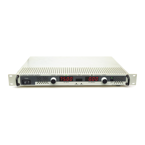
- Page 12 FIGURE 1-1. KLP SERIES POWER SUPPLY 3010226 KLP091313...
-
Page 13: Section 1 - Introduction
This manual contains instructions for installation and operation of the KLP series of 1200W out- put power, stabilized voltage or current, d-c power supplies manufactured by KEPCO, Inc., Flushing, New York, U.S.A. Digital remote operation is described in the KLP Developer’s Guide which can be downloaded from the Kepco website at www.kepcopower.com/support/opmanls.htm#klp. -
Page 14: Options
600V models. Smaller discharge steps will be supported at higher continuous rates; con- tact Kepco Applications Engineering for additional details. The RODC circuit employs protection against both peak energy and average power overload conditions by disabling only the RODC function until conditions recover to normal range;... -
Page 15: Klp Operating Regions
FIGURE 1-2. KLP OPERATING REGIONS TABLE 1-2. MODEL PARAMETERS Rated Maximum Minimum Rated Maximum Ripple and Efficiency Model number Voltage current for Programmable Current voltage for noise @115 Va-c Range rated voltage current Range rated current KLP 10-150 0-10V 120A@10V 1.9A 0-150A 8V@150A... -
Page 16: Klp Specifications
TABLE 1-3. KLP SPECIFICATIONS SPECIFICATION RATING/DESCRIPTION CONDITION/COMMENT INPUT CHARACTERISTICS nominal 100-240 Va-c Single Phase. a-c voltage (1) range 90-265 Va-c Wide Range; contact factory for opera- tion to 265V a-c. nominal range 50-60 Hz Frequency maximum 45-440 Hz Increased Leakage above 66 Hz. Power Factor typical 0.99... - Page 17 TABLE 1-3. KLP SPECIFICATIONS (Continued) SPECIFICATION RATING/DESCRIPTION CONDITION/COMMENT OUTPUT CHARACTERISTICS - CONTINUED Transient recovery excursion 1% of E max 50% load step 2A/microsecond max. for load change recovery 2 msec Return to 0.1% of setting. Turnon/turnoff overshoot Rated output, any load Rise Time Voltage 10V, 20V, 36V: 30 msec, 75V: 40 msec, 0 - E max , rated load (resistive)
-
Page 18: Physical Characteristics
TABLE 1-3. KLP SPECIFICATIONS (Continued) SPECIFICATION RATING/DESCRIPTION CONDITION/COMMENT PHYSICAL CHARACTERISTICS Dimensions English 1.735”H x 19"W x 17.5"D Depth excluding connectors and termi- nal blocks (see Figure 1-3). metric 44.45 x 482.6 x 443.7 mm Weight English 15 lbs metric 6.82kg Dielectric strength Input - Chassis 2121V d-c... - Page 19 TABLE 1-3. KLP SPECIFICATIONS (Continued) SPECIFICATION RATING/DESCRIPTION CONDITION/COMMENT PROGRAMMING CHARACTERISTICS - ANALOG Analog remote control selection Activate with jumper at analog program- Recognized during power up. ming connector isolation Safety Extra Low Voltage (SELV) Analog Input Update Rate 2Hz (0.5 Second) Applies to program- Analog input voltage digitized (12-bit ming by voltage/ resistance and read- resolution), optically isolated, then pro-...
-
Page 20: Klp Series Power Supply, Mechanical Outline Drawing
FIGURE 1-3. KLP SERIES POWER SUPPLY, MECHANICAL OUTLINE DRAWING (SHEET 1 OF 2) KLP 091313... - Page 21 FIGURE 1-3. KLP SERIES POWER SUPPLY, MECHANICAL OUTLINE DRAWING (SHEET 2 OF 2) KLP 091313...
-
Page 22: Features
FEATURES 1.5.1 LOCAL CONTROL Two front panel rotary encoders allow adjustment of voltage and current setpoints and limits. Operating mode of the power supply is indicated by lighting either a green (Constant Voltage) or amber (Constant Current) LED. The output can be enabled or disabled by the front panel DC OUTPUT switch;... -
Page 23: Overvoltage/Overcurrent Protection
1.5.4 OVERVOLTAGE/OVERCURRENT PROTECTION Overvoltage and Overcurrent protection values can be individually programmed. If the output voltage/current exceeds the overvoltage/overcurrent protection value, the protection circuit latches the output off, flashes an overvoltage (OVP) or overcurrent (OCP) error message on the status display and sets a status bit that can be retrieved through the RS 232 [standard models only], LAN [E-Series models only], or GPIB port. -
Page 24: Internal Relay
There are no operator serviceable parts inside the case. Service must be referred to authorized personnel. Using the power supply in a manner not specified by Kepco. Inc. may impair the pro- tection provided by the power supply. Observe all safety precautions noted throughout this man- ual. -
Page 25: Accessories
Mates with NEMA 5-15R receptacle (see adjacent figure). Supports restricted load power over mains voltage range of 100-136V a-c (contact Kepco Sales Engineering for details). Line Cord Set (250V/15A) 2.5m long cord set, provides for source power NEMA 6-15R 118-1137 connection. -
Page 27: Section 2 - Installation
SECTION 2 - INSTALLATION UNPACKING AND INSPECTION This instrument has been thoroughly inspected and tested prior to packing and is ready for operation. After careful unpacking, inspect for shipping damage before attempting to operate. Perform the preliminary operational check as outlined in PAR 2.5. If any indication of damage is found, file an immediate claim with the responsible transport service. -
Page 28: Rear Panel Connectors And Switches
TABLE 2-1. CONTROLS, AND INDICATORS (CONTINUED) CONTROL OR FUNCTION INDICATOR DC AMPERES Four-digit LED display that shows current settings: display a. Shows actual output current (PAR.3.2.10). b. Shows current set point or overcurrent limit when function selected (PAR. 3.2.10.2). c. Shows GPIB address (PAR. 3.2.12), baud rate (PAR. 3.2.13). d. -
Page 29: Klp Series, Rear Panel Switch And Connectors
FIGURE 2-2. KLP SERIES, REAR PANEL SWITCH AND CONNECTORS KLP-HV 091313... -
Page 30: Ieee 488 Port Connector (J4) Pin Assignments
TABLE 2-3. IEEE 488 PORT CONNECTOR (J4) PIN ASSIGNMENTS SIGNAL NAME FUNCTION I/O Line I/O Line I/O Line I/O Line End or Identify Data Valid NRFD Not Ready for Data NDAC Not Data Accepted Interface Clear Service Request Attention SHIELD Shield I/O Line I/O Line... -
Page 31: Lan Port Connector (J7) Pin Assignments [E-Series Models Only]
TABLE 2-5. LAN PORT CONNECTOR (J7) PIN ASSIGNMENTS [E-SERIES MODELS ONLY] SIGNAL NAME FUNCTION Transmit + TX– Transmit – NOT USED NOT USED NOT USED NOT USED Receive + RX– Receive – TABLE 2-6. CONTROL INPUT TERMINAL BLOCK ASSIGNMENTS TERMINAL FUNCTION Positive output monitor connection (TB5) (see PAR. -
Page 32: Source Power Requirements
SOURCE POWER REQUIREMENTS This power supply operates with the installed circuit breaker from single phase a-c mains power over the voltage and frequency ranges specified in Table 1-3 without adjustment or modification. COOLING The power devices used within the power supply are maintained within their operating tempera- ture range by means of internal heat sink assemblies cooled by three internal (d-c type) cooling fans. -
Page 33: Installation
• Then the status display reads SET (setpoint mode), the DC VOLTS display reads 0 Volts, the DC AMPERES display reads minimum Amperes (see Note 1, below). NOTES: 1. A minimum programmed current (actual value depends on model) is required to ensure proper operation of the power supply under all load conditions. -
Page 34: Safety Grounding
It is the user's responsibility to ensure that all applicable local codes for source power wiring are met. Kepco also makes a variety of prefabricated safety line cord sets available for connecting KLP to source power via conven- tional box-mounted receptacles. -
Page 35: D-C Output Grounding
It is hoped that the preceding paragraphs will be of some assistance in most cases. For help in special applications or difficult problems, consult directly with Kepco's Application Engineering Depart- ment. -
Page 36: Power Supply/Load Interface
2.7.4 POWER SUPPLY/LOAD INTERFACE The general function of a voltage or current stabilized power supply is to deliver the rated output quantities to the connected load. The load may have any conceivable characteristic: it may be fixed or variable, it may have predominantly resistive, capacitive or inductive parameters; it may be located very close to the power supply output terminals or it may be a considerable distance away. -
Page 37: Series Operation
KLP power supplies using remote sensing. Kepco strongly recommends that series applica- tions employ master/slave control (available on standard models only) as described in PAR’s. 2.7.8 and 3.2.14. Users considering series configuration of KLP are urged to contact Kepco Application Engineering first to discuss application details before ordering KLP power supplies intended for Series operation. -
Page 38: Series Connection Using Remote Sensing
2.7.6 FIGURE 2-4. SERIES CONNECTION USING REMOTE SENSING FIGURE 2-5. PARALLEL CONNECTIONS USING REMOTE SENSING 2-12 KLP-HV 091313... -
Page 39: Load Sharing
For the low-voltage models (10V, 20V, 36V) Kepco advises the use of bus bar conductors where possible; for higher voltage models (75V - 600V), appropriately sized twisted conductor pairs terminated with wire ferrules are recommended (contact Kepco Applications Engineering for details). -
Page 40: Master/Slave Configurations [Standard Models Only]
If GPIB control of the master/slave pair is desired, the user must connect to the master unit using an “in-line” style connector, as the commonly-used stackable connector will interfere phys- ically with the RS 232 connector above it. Contact Kepco Sales Engineering for additional guid- ance. -
Page 41: Digital Connections
e. Fault Connections (RELAY_NC, RELAY_COM, RELAY_NO It is recommended that normally open and normally closed relay signals RELAY_NC (pin 10) and/or RELAY_NO (pin 2), respectively, be twisted together with RELAY_COM (pin 4) as needed to eliminate noise pickup. See PAR. 3.2.17.1 to configure internal relay. f. -
Page 43: Section 3 - Operation
SECTION 3 - OPERATION GENERAL This section explains how to operate the KLP Power Supply. Series KLP feature three modes of operation: • Local Mode (see PAR. 3.2): This is the default operating mode, providing full access to all programming and readback functions via front panel displays, controls, and indica- tors. -
Page 44: Power-Up Built-In Test Error Codes
• Status display flashes PROT for 2 seconds while DC VOLTS and DC AMPERES dis- plays show previously stored OVP and OCP trigger levels. NOTE: to reprogram OVP or OCP, refer to PAR. 3.2.11. NOTE: To eliminate the display of model, virtual model, and protection levels on power-up, refer to PAR. -
Page 45: Setting Local/Remote Mode
NOTE: A minimum programmed current is required to ensure proper operation of the power supply under all load conditions. Programmed current is automatically set to be at least the minimum current (actual value depends on model, see Table 1-2). • Since the output is off, Constant Voltage (CV) mode indicator (green LED) and Con- stant Current (CC) indicator (amber LED) are off. -
Page 46: Remote With Local (Front Panel) Lockout
3.2.2.1 REMOTE WITH LOCAL (FRONT PANEL) LOCKOUT To prevent unauthorized setting of the power supply to Local mode, a local lockout mode can be enabled which prevents the power supply from being restored to local mode via the front panel. With the power supply turned off, set the ANALOG I/O DIP switch, position 5 (see Table 2-2) to ON. -
Page 47: Enabling/Disabling Output Power
3. Tap DC OUTPUT switch, then rotate either the VOLTAGE or CURRENT control until status display reads ADJ. The DC VOLTS display shows C--F when normal rotation produces coarse adjustment, F--C when normal rotation produces fine adjustment. FUNCTION––––––––VIRT* (PAR. 3.2.9) –––CNFG (PAR 3.2.16)––––VERS ––... -
Page 48: Enabling/Disabling The Output Using Remote Inhibit
To enable the output, first tap either VOLTAGE or CURRENT control once to exit setpoint mode (SET disappears from the status display) then tap the DC OUTPUT switch once. The DC OUT- PUT indicator goes on to indicate the output is enabled. To disable the output, press and release the DC OUTPUT switch again. -
Page 49: Checking Voltage/Current Setpoints
3.2.7 CHECKING VOLTAGE/CURRENT SETPOINTS CAUTION: BEFORE ENABLING THE OUTPUT ALWAYS CHECK THE SETPOINTS TO AVOID POSSIBLE DAMAGE TO THE LOAD. Check the voltage and current set points by tapping either the VOLTAGE or CURRENT control. The status display reads SET, and the DC VOLTS and DC AMPERES displays show the stored setpoints. -
Page 50: Setting Voltage Or Current
front panel (see PAR. 3.3.2) should be checked to ensure that there are no settings outside the range permitted by the new maximum programmable voltage and current. • Storage of User-programmed Active Settings (Save/Recall). • User-determined output Sequences. • External Triggers: VOLT:TRIG and CURR:TRIG values •... -
Page 51: Real-Time Voltage/Current Adjustment
3.2.10.1 REAL-TIME VOLTAGE/CURRENT ADJUSTMENT Rotating the associated control will change the output voltage or current in real-time only if the output is enabled. If the unit is in constant voltage mode (CV indicator lit) the DC VOLTS display shows the actual output voltage as the VOLTAGE control is rotated. Similarly, if the unit is in constant current mode (CC indicator lit) the DC AMPERES display shows the actual output cur- rent as the CURRENT control is rotated. -
Page 52: Viewing/Changing Overvoltage Or Overcurrent Protection Values
3 to the OFF (up) position; at next power-up, the stored value buffer is cleared and setpoints will default to zero volts and minimum current. NOTE: If the virtual model for the power supply is altered, the last settings are reset to zero volts and minimum current. -
Page 53: Changing Rs 232 Baud Rate [Standard Models Only]
4. Rotate the CURRENT control to change the GPIB address, then tap the DC OUTPUT switch to accept the displayed GPIB address. The display briefly reads DONE, then returns to ADDR. 5. Rotate the VOLTAGE control until display reads EXIT, then tap the DC OUTPUT switch to exit 3.2.13 CHANGING RS 232 BAUD RATE [STANDARD MODELS ONLY]... -
Page 54: Configure Power Supply As Master [Standard Models Only]
• The DC AMPERES display shows the maximum number of units in the configuration. • The factory default is standalone operation (DC VOLTS and DC AMPERES show 1). 4. To change the configuration tap the DC OUTPUT switch once. The DC VOLTS and DC AMPERES start blinking. -
Page 55: Operating The Master/Slave Configuration [Standard Models Only]
• Specify the total number of units in the configuration to 2 by rotating the CURRENT con- trol. • Specify the unit number to be assigned (1 = master) by rotating the VOLTAGE control. 5. Press DC OUTPUT to accept the displayed settings. The unit briefly flashes WAIT, then restarts with the new settings;... -
Page 56: Restoring The Master/Slave Configuration To Standalone Operation [Standard Models Only]
• Calibration cannot be performed on a master/slave pair; the individual units must be reconfigured back to independent mode (PAR 3.2.14.4) and then calibrated as individual units. • Baud rate is automatically adjusted to highest supportable rate as part of master/slave setup and cannot be adjusted by user. - Page 57 • DHCP - DHCP status is displayed in the DC VOLTS display. To change the setting press DC OUTPUT switch, then rotate either VOLTAGE or CURRENT control to see desired setting and press DC OUTPUT switch to save. • ON - The KLP requests an IP address from the DHCP server. (AUTOIP set to OFF.) •...
-
Page 58: Unit Configuration
3.2.16 UNIT CONFIGURATION The Configuration Function identifies the firmware version, the KLP model, and the options installed. 1. If the status display shows SET, tap either the CURRENT or VOLTAGE controls to take the unit out of setpoint mode (status display goes from SET to blank). 2. -
Page 59: Internal Relay Control
• ANRB - Analog Output Full Scale calibration voltages (see PAR. 3.2.17.4) • ANPR - Analog Input Full Scale calibration voltages (see PAR. 3.2.17.5) • LBT - [Standard models only] Loop Back Test used to isolate RS 232 communication problems (see KLP Developer’s Guide). •... -
Page 60: Quick Boot
a. If FLT is selected, rotate VOLTAGE or CURRENT control to select NORM, V->C, or C->V. in the status display. (1) To select NORM, tap the DC OUTPUT switch to save selection; unit returns to RELY menu. (2) To select V->C or C->V, first set the delay. While V->C or C->V is in the status dis- play, the DC AMPERES display shows the delay in seconds, from 000.5 to 128.0: NNND, where NNN is an integer from 0 to 128 and D will be either .0 or .5 (000.0 is not permitted). -
Page 61: System Configuration Functions
3. To exit, rotate either VOLTAGE or CURRENT control until the status display reads RTN, then tap the DC OUTPUT switch. To exit the UTIL menu rotate either VOLTAGE or CURRENT control until the status display reads EXIT, then tap the DC OUTPUT switch. 3.2.17.3 SYSTEM CONFIGURATION FUNCTIONS The system configuration functions allow the user to determine 1) whether the Remote Inhibit... -
Page 62: Fault Recovery Configuration
ming ports. Recovery cannot be initiated by toggling the remote inhibit line at the analog programming port. This option provides greater operator convenience by eliminating the need to reboot the power supply while preserving a safe response (output off), but it is the user’s responsibility to NOT attempt multiple consecutive restarts without eliminating the fault condition. -
Page 63: Analog Output Full Scale Calibration
1. Enter UTIL menu (see PAR. 3.2.17, steps 1 through 3) and rotate either VOLTAGE or CUR- RENT control until status display reads SYST, then tap DC OUTPUT switch. Rotate either VOLTAGE or CURRENT control to until the status display reads RCOV. The DC VOLTS and DC AMPERES displays show a series of bars that give a snapshot pic- ture of the recovery configuration as defined in Figure 3-2. -
Page 64: Analog Input Full Scale Calibration
4. Tap the DC OUTPUT switch to accept the new settings (blinking stops) or use a thin tool (e.g., a paper clip) to press the FUNCTION switch to cancel the operation. 5. To exit, rotate either VOLTAGE or CURRENT control until the status display reads RTN, then tap the DC OUTPUT switch. -
Page 65: Rs 232 Factory Defaults [Standard Models Only]
• ON (enabled) NOTE: Kepco strongly recommends the XON XOFF method for data transfer via RS 232 protocol for all Kepco products. If this method is not selected, it is the user's responsibility to ensure completion of any response by the power supply prior to issuance of subsequent commands. -
Page 66: Additional Functions Not Available From The Front Panel
Kepco provides three instrument drivers, IVI-COM, LabView G and VXI plug&play which sim- plify programming of the KLP power supply via the digital interfaces. These drivers are described in the KLP Developer’s Guide and can be downloaded from the Kepco web site at: http://www.kepcopower.com/drivers/ 3.3.3... -
Page 67: Troubleshooting Lan Communication Problems
3.3.6.2 FINDING KEPCO POWER SUPPLIES ON THE LAN [E-SERIES MODELS ONLY] The PSfind utility can be downloaded from the Kepco web site at www.kepcopower.com/driv- ers/drivers-dl3.htm#klp. This utility finds all operational Kepco power supplies connected to the LAN and then shows the MAC and IP addresses of the models found. To run the utility from your PC download the psfind.zip file to your computer. -
Page 68: Launch Web Interface [E-Series Models Only]
Although most current browsers will work, Kepco recommends the following as fully supported: IE 5.5 and higher, Netscape 6 and higher and Firefox 1.0 and higher. Popup blocking must be disabled and Javascript must be enabled for proper operation. -
Page 69: Instrument Configuration Using Web Interface [E-Series Models Only]
FIGURE 3-4. WEB INTERFACE HOME PAGE (UNIT DESCRIPTION) 3.3.6.4 INSTRUMENT CONFIGURATION USING WEB INTERFACE [E-SERIES MODELS ONLY] Click on CONFIGURE INSTRUMENT at the left to view the INSTRUMENT Configuration page (Figure 3-5). The parameters that can be configured from this page are arranged in two groups. The top group requires the unit password (see PAR. -
Page 70: Lan Configuration Using Web Interface [E-Series Models Only]
Once the configuration has been altered by changing the applicable fields, click SUBMIT to save the new configuration, or NO CHANGE to clear and reload the page without saving (NO CHANGE is the same as browser refresh or reload). NOTE: When the SUBMIT button is clicked, only one changed line is processed. If multiple configuration changes are entered, lines are processed in sequence from top to bot- tom, and multiple presses of SUBMIT are needed to process all the changes. -
Page 71: Web Interface Configure Lan Page
• The OPERATE INSTRUMENT password restricts the ability to modify the OPERATE INSTRUMENT page settings. The settings can still be viewed while password protected • The CONFIGURE INSTRUMENT password restricts the ability to change some INSTRUMENT configuration parameters shown on the CONFIGURE INSTRUMENT page. -
Page 72: Operating The Unit Using Web Interface [E-Series Models Only]
When SUBMIT is clicked after new IP address information is entered, the front panel LAN indi- cator blinks rapidly while the unit validates the IP address. If the address is valid, the browser returns to the INSTRUMENT DESCRIPTION page. If the address entered is already in use, the following note appears towards the top of the page: NOTE: IP Address is in use. -
Page 73: Web Interface Operate Instrument Page
ture. These settings are cleared when a calibration is performed. Click SAVE/RECALL to open the Save/Recall Dialog Box (Figure 3-9). FIGURE 3-7. WEB INTERFACE OPERATE INSTRUMENT PAGE FIGURE 3-8. PROTECTION DIALOG BOX FIGURE 3-9. SAVE/RECALL DIALOG BOX 3-31 KLP091313... -
Page 74: Resetting The Unit (*Rst) [E-Series Models Only]
NOTE: When the SAVE/RECALL tab is initially selected, parameters for all locations appear as empty even when there are values stored from previous sessions. Click the Pre- view button first to avoid overwriting existing data. • To view currently stored settings: Enter a location (1 to 40) in the box between Save @ and Preview buttons, then click Preview button. -
Page 75: List Dialog Box
Create the List. Click LIST to open the List dialog box (Figure 3-11). Each location defines the Create the List. Click LIST to open the List dialog box (Figure 3-11). Each location defines the values for one step: voltage and current, and a dwell time duration (between 0.5 and 655.36 seconds). -
Page 76: Setting Virtual Model [E-Series Models Only]
may take a few seconds to process; the percentage complete is indicated below the Create Ramp button. FIGURE 3-12. ADDING MULTIPLE STEPS (RAMPS) TO LIST Execute the List. Steps may be added to a list using Add to List, Current Ramp or Voltage Ramp buttons, however the total number of steps can not exceed 100. -
Page 77: Remote Programming Using Analog Signals
FIGURE 3-13. VIRTUAL MODEL DIALOG BOX REMOTE PROGRAMMING USING ANALOG SIGNALS Vref and Cref, present at the Analog Port (see J2, Figure 2-2 and Table 2-7) are the respective voltage and current programming inputs, used for programming the power supply output in pro- portion to either and analog voltage drive signal or programming resistance. -
Page 78: Programming With External Resistance
3.4.1 PROGRAMMING WITH EXTERNAL RESISTANCE Figure 3-14 is a simplified diagrams of the KLP showing the switch configuration and external connections required for analog programming using an external resistance. 1. Virtual model (PAR. 3.2.9) and Overvoltage and Overcurrent settings (PAR 3.4.3) must be established via either local programming or digital remote programming prior to initiating Analog Remote programming. -
Page 79: Programming With External Voltage
3.4.2 PROGRAMMING WITH EXTERNAL VOLTAGE Figure 3-15 is a simplified diagrams of the KLP showing the switch configuration and external connections required for analog programming using an external voltage. 1. Virtual Model (PAR. 3.2.9) and Overvoltage and Overcurrent settings (PAR. 3.4.3) must be established via either local programming or digital remote programming prior to initiating Analog Remote programming. -
Page 80: Changing Overvoltage Or Overcurrent Protection Values In Analog Programming Mode
3.4.3 CHANGING OVERVOLTAGE OR OVERCURRENT PROTECTION VALUES IN ANALOG PROGRAMMING MODE Overvoltage and overcurrent values can not be changed using analog remote programming; this can only be done by issuing a command via the GPIB or RS 232 port, or via local mode from the front panel (enter local mode by pressing the VOLTAGE and CURRENT adjustment controls at the same time, then see PAR. -
Page 81: Section 4 - Calibration
SECTION 4 - CALIBRATION GENERAL This section contains the calibration instructions for the Power Supply. It is recommended that the user be familiar with Local Mode operation (PAR.3.2) before calibrating the unit. A full calibration consist of a voltage calibration and a current calibration. Both voltage and cur- rent calibrations consist of a zero and a full scale calibration. -
Page 82: Calibration Using Front Panel Controls In Local Mode
CALIBRATION USING FRONT PANEL CONTROLS IN LOCAL MODE For voltage calibration all loads must be disconnected and the sense terminals connected to the corresponding output terminals. The digital voltmeter will be connected to the output of the power supply. For current calibration after disconnecting all loads an appropriate shunt resistor will be connected across the output terminals and the digital voltmeter will be connected to the sense terminals of the shunt resistor. -
Page 83: Voltage Calibration (Local)
9. When the password is accepted, status display reads V ?. Rotating either VOLTAGE or CURRENT control continuously cycles through all the calibration choices. The status display reads: V ? for voltage calibration C ? for current calibration, EXT? for remote analog cali- bration, and EXIT to save the calibrated results. -
Page 84: External Calibration (Local)
4. Tap the DC OUTPUT switch to accept the value. The status display reads CMAX. Rotate the CURRENT control to increase or decrease the DVM reading until the DVM reading corre- sponds as close as possible to (but not less than) the maximum rated current (see Table 1-2) Calculate current as follows: I (Amperes) = DVM reading (Volts) / Shunt Resistance (Ohms). -
Page 85: Calibration Using Vxi Plug&Play Driver
KLP which can be downloaded from the Kepco website at: www.kepcopower.com/ drivers/. Unzip the files and doubleclick on setup.exe to install the driver. The Kepco\klp folder will be added to the Start - Programs folder. Doubleclick KLPCTRL.exe to run the program, and refer to the KLP Developer’s Guide in the Kepco\klp folder for details about using the soft front panel. -
Page 86: Voltage Calibration (Vxi Plug&Play Driver Demo)
FIGURE 4-2. CALIBRATION WINDOW 8. Use the computer keyboard to enter the password in the text box displaying the word PASS- WORD, then press the ENTER key. 9. If password is correct, the status display on the VXI main panel reads CAL and the buttons on Calibration Screen (Figure 4-1) are enabled (highlighted). -
Page 87: Current Calibration (Vxi Plug&Play Demo)
FIGURE 4-3. VOLTAGE CALIBRATION WINDOW 2. Click the Press to ACCEPT button to accept the value. The status display then reads VMAX. Monitor DVM and click the “+” button to increase and the “–“ to decrease the output voltage until the DVM reads as close as possible to maximum rated voltage. 3. -
Page 88: Current Calibration Window
FIGURE 4-4. CURRENT CALIBRATION WINDOW 2. Monitor DVM and click the “+” button to increase and the “–“ to decrease the output current until the DVM reads as close as possible to maximum rated current (Calculate current as fol- lows: I (Amperes) = DVM reading (Volts) / Shunt Resistance (Ohms). -
Page 89: Analog Reference Calibration (Vxi Plug&Play Demo)
6. Click the PRESS TO ACCEPT button to accept the value. The status display will not change. Click the ANALOG REF button on the calibration window to proceed to external calibration (see PAR. 4.4.3). 4.4.3 ANALOG REFERENCE CALIBRATION (VXI plug&play DEMO) During analog reference calibration the external analog reference voltages used to establish full scale output current and voltage are calibrated. -
Page 90: Calibration Exit (Vxi Plug&Play Demo)
4.4.4 CALIBRATION EXIT (VXI plug&play DEMO) NOTE: Clicking the Calibrate Close button on the VXI main panel will exit calibration WITH- OUT saving any calibration data. 1. Click the SAVE CALIBRATION button on the calibration window to save this calibration. 2. -
Page 91: Restoring Prior Calibration Values
During item final test at Kepco, Factory values are established during calibration and are copied to all three locations. Should a unit be returned to Kepco for repair or retest, the recalibration accompanying this testing will overwrite the contents of all three locations with the latest Factory values. -
Page 93: Klp Installation/Operation Summary
4. Connect power supply to power source using one of the following: See PAR. 2.7.2 for additional information. • Use standard NEMA line cord set from Kepco (see Table 1-5) or customized line cord using user-wireable mating connector (supplied) in conjunction with user-selected line cord or discrete wiring as applicable. - Page 94 How do I view/change the virtual model settings? See PAR. 3.2.9 for description of virtual model. If status shows SET, exit set- point mode (tap either knob once). Use thin tool to press FUNCTION once; status reads VIRT. VOLTS and AMPS displays show the maximum voltage and current of the present virtual model.
Need help?
Do you have a question about the KLP 10-150-(2) and is the answer not in the manual?
Questions and answers