Table of Contents
Advertisement
Quick Links
Download this manual
See also:
User Manual
OPERATOR'S MANUAL
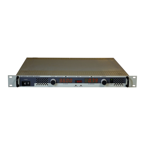
1200 WATT PROGRAMMABLE POWER SUPPLY
KEPCO INC.
An ISO 9001 Company.
IMPORTANT NOTES:
1)
This manual is valid for the following Model and associated serial numbers:
MODEL
KLP 20-120-1200
KLP 36-60-1200
KLP 75-33-1200
KLP 150-16-1200
KLP 300-8-1200
KLP 600-4-1200
2)
A Change Page may be included at the end of the manual. All applicable changes and
revision number changes are documented with reference to the equipment serial num-
bers. Before using this Instruction Manual, check your equipment serial number to identify
your model. If in doubt, contact your nearest Kepco Representative, or the Kepco Docu-
mentation Office in New York, (718) 461-7000, requesting the correct revision for your
particular model and serial number.
3)
The contents of this manual are protected by copyright. Reproduction of any part can be
made only with the specific written permission of Kepco, Inc.
Data subject to change without notice.
©2008, KEPCO, INC
P/N 243-0979-e
KEPCO, INC. ! 131-38 SANFORD AVENUE ! FLUSHING, NY. 11355 U.S.A. ! TEL (718) 461-7000 ! FAX (718) 767-1102
KLP SERIES
POWER SUPPLY
MODEL
KLP SERIES
POWER SUPPLY
ORDER NO.
SERIAL NO.
email: hq@kepcopower.com ! World Wide Web: http://www.kepcopower.com
REV. NO.
REV. NO.
REV.11
REV.11
REV.24
REV.21
REV.13
REV.2
KEPCO
THE POWER SUPPLIER™
®
Advertisement
Table of Contents

Subscribe to Our Youtube Channel
Related Manuals for KEPCO KLP SERIES


Summary of Contents for KEPCO KLP SERIES
-
Page 1: Power Supply
Data subject to change without notice. KEPCO ® ©2008, KEPCO, INC P/N 243-0979-e THE POWER SUPPLIER™ KEPCO, INC. ! 131-38 SANFORD AVENUE ! FLUSHING, NY. 11355 U.S.A. ! TEL (718) 461-7000 ! FAX (718) 767-1102 email: hq@kepcopower.com ! World Wide Web: http://www.kepcopower.com... -
Page 3: Declaration Of Conformity
93/68/EEC (CE mark) Standard to which Conformity is declared: EN61010-1:2001 (Safety requirements for electrical equipment for measurement, control and laboratory use - Part 1) KEPCO INC. Manufacturer's Name and Address: 131-38 SANFORD AVENUE FLUSHING, N.Y. 11352 USA Importer's Name and Address:... - Page 4 There are no user or operator serviceable parts within the product enclosure. Refer all servicing to qualified and trained Kepco service technicians. 228-1351 COND/CONFORM 073008...
-
Page 5: Safety Instructions
SAFETY INSTRUCTIONS 1. Installation, Operation and Service Precautions This product is designed for use in accordance with EN 61010-1 and UL 3101 for Installation Category 2, Pollution Degree 2. Hazardous voltages are present within this product during normal operation. The prod- uct should never be operated with the cover removed unless equivalent protection of the operator from accidental contact with hazardous internal voltages is provided: There are no operator serviceable parts or adjustments within the product enclosure. -
Page 7: Table Of Contents
TABLE OF CONTENTS SECTION PAGE SECTION 1 - INTRODUCTION Scope of Manual............................1-1 General Description ............................ 1-1 Specifications.............................. 1-1 Features..............................1-8 1.4.1 Local Control ............................1-8 1.4.2 Remote Control ............................1-8 1.4.2.1 Digital Programming........................... 1-8 1.4.2.2 Analog Programming ......................... 1-8 1.4.3 Digital Calibration ............................ - Page 8 TABLE OF CONTENTS SECTION PAGE 3.2.6 Setting voltage or current........................3-5 3.2.6.1 Real-time Voltage/Current Adjustment ....................3-6 3.2.6.2 Setpoint Adjustment .......................... 3-6 3.2.6.3 Last Setting Recall..........................3-6 3.2.7 Viewing/Changing Overvoltage or Overcurrent Protection Values ............3-6 3.2.8 Changing GPIB Address......................... 3-7 3.2.9 Changing RS232 Baud Rate ........................
- Page 9 TABLE OF CONTENTS SECTION PAGE 3.6.4.5 Data Separator........................... 3-23 3.6.4.6 Message Unit Separator ........................3-23 3.6.4.7 Root Specifier............................. 3-23 3.6.4.8 Message Terminator .......................... 3-24 3.6.5 Understanding The Command Structure....................3-24 3.6.6 Program Message Syntax Summary....................... 3-26 3.6.7 Status Reporting............................3-26 3.6.7.1 Status Reporting Structure.........................
- Page 10 TABLE OF CONTENTS SECTION PAGE CAL Commands and Queries ........................B-2 DISPlay:TEXT? Query ..........................B-2 INITiate[:IMMediate] Command ......................... B-2 INITiate:CONTinuous Command ....................... B-3 INITiate:CONTinuous? Query ........................B-3 [SOURce:]LIST:CLEar Command ......................B-3 B.10 [SOURce:]LIST:CONTrol Command......................B-4 B.11 [SOURce:]LIST:CONTrol? QUERY ......................B-4 B.12 [SOURce:]LIST:COUNt Command ......................
- Page 11 TABLE OF CONTENTS SECTION PAGE B.62 STATus:QUEStionable[:EVENt]? Query....................B-16 B.63 STATus:QUEStionable:CONDition? Query ....................B-16 B.64 STATus:QUEStionable:ENABle Command ....................B-16 B.65 STATus:QUEStionable:ENABle? Query....................B-16 B.66 SYSTem:COMMunication:GPIB:ADDR Command ................B-17 B.67 SYSTem:COMMunication:GPIB:ADDR ? Query................. B-17 B.68 SYSTem:COMMunication:SERial:BAUD CommanD................. B-17 B.69 SYSTem:COMMunication:SERial:BAUD? Query ..................B-17 B.70 SYSTem:COMMunication:SERial:ECHO Command................
- Page 12 PAGE KLP Series Power Supply ........................... viii KLP Operating Regions..........................1-2 KLP Series Power Supply, Mechanical Outline Drawing ................1-6 KLP Series, Front Panel Controls and Indicators..................2-1 KLP Series, Rear Panel Switch and Connectors ..................2-2 Remote Sensing............................2-10 Series Connection using Remote Sensing....................
- Page 13 LIST OF TABLES TABLE TITLE PAGE Model Parameters ............................1-2 KLP Specifications ............................1-3 Equipment Supplied ............................1-10 Accessories ..............................1-11 Safety Symbols ............................1-11 Controls, and Indicators ..........................2-1 Analog I/O Switch Functions ........................2-3 IEEE 488 Port Connector (J4) Pin Assignments ..................2-3 RS232 Port Connector (J3) Pin Assignments .....................2-4 Rear Terminal block Assignments ......................2-4 Analog I/O Connector (J2) Pin Assignments ....................2-4 Input Current Service Rating and Conductor Sizes ..................2-7...
- Page 14 FIGURE 1-1. KLP SERIES POWER SUPPLY viii KLP073008...
-
Page 15: Section 1 - Introduction
SECTION 1 - INTRODUCTION SCOPE OF MANUAL This manual contains instructions for the installation, operation and service of the KLP series of 1200W output power, stabilized voltage or current, d-c power supplies manufactured by KEPCO, Inc., Flushing, New York, U.S.A. -
Page 16: Klp Operating Regions
FIGURE 1-2. KLP OPERATING REGIONS TABLE 1-1. MODEL PARAMETERS Rated Maximum Minimum Rated Maximum Ripple and noise Efficiency Model number Voltage current for programmable Current voltage for @115 Va-c current Range Range rated voltage rated current KLP 20-120-1200 0-20V 60A@20V 1.6A 0-120A 10V@120A... -
Page 17: Klp Specifications
TABLE 1-2. KLP SPECIFICATIONS SPECIFICATION RATING/DESCRIPTION CONDITION INPUT CHARACTERISTICS nominal 110-240 Va-c Single Phase a-c voltage range 100-255 Va-c Wide Range; contact factory for opera- tion to 265V a-c. d-c voltage range 125-420 Vd-c No regulatory agency approval nominal range 50-60 Hz Frequency maximum... -
Page 18: Physical Characteristics
TABLE 1-2. KLP SPECIFICATIONS (Continued) SPECIFICATION RATING/DESCRIPTION CONDITION GENERAL (ENVIRONMENTAL) SPECIFICATIONS Temperature operating -20 to +50 deg C Rated load. Derate at 25W per °C between 50 and 70°C. storage -40 to +85 deg C Cooling 3 internal d-c fans exhaust to the rear Humidity 0 to 95% RH... - Page 19 TABLE 1-2. KLP SPECIFICATIONS (Continued) SPECIFICATION RATING/DESCRIPTION CONDITION PROGRAMMING CHARACTERISTICS - ANALOG Analog remote control selection Activate with jumper at analog program- Recognized during power up. ming connector isolation Safety Extra Low Voltage (SELV) referenced to chassis Programming by voltage voltage 0-10V Programmable current minimal value-10V...
-
Page 20: Klp Series Power Supply, Mechanical Outline Drawing
R\DWG\MECH\3010266 FIGURE 1-3. KLP SERIES POWER SUPPLY, MECHANICAL OUTLINE DRAWING (SHEET 1 OF 2) KLP 073008... - Page 21 FIGURE 1-3. KLP SERIES POWER SUPPLY, MECHANICAL OUTLINE DRAWING (SHEET 2 OF 2) KLP 073008...
-
Page 22: Features
FEATURES 1.4.1 LOCAL CONTROL Two front panel rotary encoders allow setting of voltage and current setpoints and limits. Oper- ating mode of the power supply is indicated by lighting either a green (Constant Voltage) or amber (Constant Current) LED. The output can be enabled or disabled by the front panel DC OUTPUT switch;... -
Page 23: Overvoltage/Overcurrent Protection
1.4.9 BUILT-IN PROTECTION KLP Series Power Supplies provide built-in protection against the conditions listed below. In each case, a detected fault results in immediate latched shutdown of the power supply output. In addition, the status display flashes the appropriate indication and the status bit is set for retrieval through either of the digital programming ports. -
Page 24: Internal Relay
There are no operator serviceable parts inside the case. Service must be referred to authorized personnel. Using the power supply in a manner not specified by Kepco. Inc. may impair the pro- tection provided by the power supply. Observe all safety precautions noted throughout this man- ual. -
Page 25: Accessories
Mates with NEMA 5-15R receptacle (see adjacent figure). Supports restricted load power over mains voltage range of 90-136V a-c (contact Kepco Sales Engineering for details). Line Cord Set (250V/15A) 2.5m long cord set, provides for source power NEMA 6-15R 118-1137 connection. -
Page 27: Section 2 - Installation
FRONT PANEL CONTROLS AND INDICATORS. Refer to Figure 2-1 and Table 2-1. 2.2.2 REAR PANEL CONNECTORS AND SWITCH. Refer to Figure 2-2 and Tables 2-2 through 2- FIGURE 2-1. KLP SERIES, FRONT PANEL CONTROLS AND INDICATORS TABLE 2-1. CONTROLS, AND INDICATORS FIGURE 2-1 CONTROL OR FUNCTION INDEX NO. -
Page 28: Klp Series, Rear Panel Switch And Connectors
RS232 baud rate (PAR. 3.2.9) and (for -1200 models) set user-determined limits on voltage and current (virtual model) (PAR. 3.2.5). NOTE: Requires a thin tool (e.g., end of paper clip) to press switch. FIGURE 2-2. KLP SERIES, REAR PANEL SWITCH AND CONNECTORS KLP-HV 073008... -
Page 29: Analog I/O Switch Functions
TABLE 2-2. ANALOG I/O SWITCH FUNCTIONS DIP SWITCH FUNCTION SETTINGS POSITION Allows analog programming commands for voltage to be provided Selects Resistance by either variable voltage (PAR. 3.7.3) or resistance (PAR. 3.7.2). OFF: Selects Voltage (factory When resistance mode is selected, an internal 1mA current genera- default) tor provides the reference for voltage programming. -
Page 30: Rs232 Port Connector (J3) Pin Assignments
TABLE 2-4. RS232 PORT CONNECTOR (J3) PIN ASSIGNMENTS CONNECTOR SIGNAL NAME FUNCTION NOTE: A null modem cable (see Table 1-4) is required for nearly all applications, with the exception of those in which RXD and TXD line transposition is accomplished via external hardware (e.g. older Apple MAC computers with D-sub serial port). SGND Signal Ground Receive Data... -
Page 31: Source Power Requirements
SOURCE POWER REQUIREMENTS This power supply operates with the installed circuit breaker from either d-c or single phase a-c mains power over the voltage and frequency ranges specified in Table 1-2 without adjustment or modification. COOLING The power devices used within the power supply are maintained within their operating tempera- ture range by means of internal heat sink assemblies cooled by three internal (d-c type) cooling fans. -
Page 32: Installation
• Then the status display reads SET (setpoint mode), the DC VOLTS display reads 0000 Volts, the DC AMPERES display reads minimum Amperes (see Note 1, below). NOTES: 1. A minimum programmed current (actual value depends on model) is required to ensure proper operation of the power supply under all load conditions. -
Page 33: Safety Grounding
It is the user's responsibility to ensure that all applicable local codes for source power wiring are met. Kepco also makes a variety of prefabricated safety line cord sets available for connecting KLP to source power via conven- tional box-mounted receptacles. -
Page 34: D-C Output Grounding
For other options please contact Kepco Sales Engineering with specific requirements. WARNING IT IS IMPERATIVE THAT THE USER PROVIDE ALL THREE SOURCE WIRE CONNEC- TIONS, AS THIS CONNECTION IS THE SAFETY GROUND PROVISION! 2.7.3 D-C OUTPUT GROUNDING Connections between the power supply and the load and sensing connections may, despite precautions such as shielding, twisting of wire pairs, etc., be influenced by radiated noise, or... -
Page 35: Power Supply/Load Interface
2.7.4 POWER SUPPLY/LOAD INTERFACE The general function of a voltage or current stabilized power supply is to deliver the rated output quantities to the connected load. The load may have any conceivable characteristic: it may be fixed or variable, it may have predominantly resistive, capacitive or inductive parameters; it may be located very close to the power supply output terminals or it may be a considerable distance away. -
Page 36: Series Operation
The user must also respect the ±600V d-c maximum isolation from output to chassis when determining the maximum series voltage. Figure 2-4 shows a series connection of two KLP power supplies using remote sensing. Kepco strongly recommends that series applica- tions employ master/slave control as described in PAR’s. 2.7.8 and 3.2.10. -
Page 37: Series Connection Using Remote Sensing
FIGURE 2-4. SERIES CONNECTION USING REMOTE SENSING FIGURE 2-5. PARALLEL CONNECTIONS USING REMOTE SENSING 2-11 KLP-HV 073008... -
Page 38: Load Sharing
2.7.7.1 LOAD SHARING When operating two or more power supplies in parallel, either for capacity or redundancy, it is desirable to distribute the load equally among all of the power supplies in order to improve per- formance, reduce stress and increase reliability. KLP power supplies incorporate active circuitry which forces multiple power supplies wired in parallel to share load current, both in voltage- and current-mode regulation. -
Page 39: Internal Relay Configuration
These signals must be protected from radiated and conducted noise as well as from physical contact with non-valid driving sources. The following subsections address specific programming signal applications; in general, however, when accessing this connector from distant locations or high-noise environments, it is recommended that a shielded cable be used, with the shield terminated to the system's single point ground. -
Page 41: Section 3 - Operation
SECTION 3 - OPERATION GENERAL This section explains how to operate the KLP Power Supply. Series KLP feature three modes of operation: • Local Mode: This is the default operating mode, providing full access to all programming and readback functions via front panel displays, controls, and indicators (see PAR. 3.2). •... -
Page 42: Setting Local/Remote Mode
• output is disabled (green DC OUTPUT indicator is off). If remote analog mode is selected (PAR. 3.7), output is enabled unless Remote Inhibit, pin 8 of the Analog I/O Connector (see Figure 2-2 and Table 2-6) is grounded. • DC VOLTS and DC AMPERES displays show programmed output conditions: either 0 Volts, minimum Amperes (see NOTE, PAR. -
Page 43: Remote With Local (Front Panel) Lockout
NOTE: During both LOCAL and DIGITAL REMOTE operation, the analog readback signals (voltage and current) remain available, as does the remote inhibit signal; only program- ming signals are disregarded. ANALOG REMOTE: With power supply turned off, ground Analog I/O port pin 12. Refer to PAR. 2.7.9 to configure the Analog I/O Port;... -
Page 44: Checking Voltage/Current Setpoints
3.2.4 CHECKING VOLTAGE/CURRENT SETPOINTS CAUTION: WHEN THE OUTPUT IS DISABLED, THE DC VOLTS AND DC AMPERES DIS- PLAYS SHOW THE ACTUAL OUTPUT VOLTAGE AND CURRENT. BEFORE ENABLING THE OUTPUT ALWAYS CHECK THE SETPOINTS TO AVOID POS- SIBLE DAMAGE TO THE LOAD. Check the voltage and current set points by tapping either the VOLTAGE or CURRENT control. -
Page 45: Setting Voltage Or Current
To define a virtual model, proceed as follows. (To establish a virtual model using SCPI com- mands, use VOLT:LIM:HIGH (see PAR. B.49) and CURR:LIM:HIGH (see PAR. B.37), respec- tively.) 1. If the status display shows SET, tap either the CURRENT or VOLTAGE controls to take the unit out of setpoint mode (status display goes from SET to blank) 2. -
Page 46: Real-Time Voltage/Current Adjustment
3.2.6.1 REAL-TIME VOLTAGE/CURRENT ADJUSTMENT Rotating the associated control will change the output voltage or current in real-time only if the output is enabled. If the unit is in constant voltage mode (CV indicator lit) the DC VOLTS display shows the actual output voltage as the VOLTAGE control is rotated. Similarly, if the unit is in constant current mode (CC indicator lit) the DC AMPERES display shows the actual output cur- rent as the CURRENT control is rotated. -
Page 47: Changing Gpib Address
age/current exceeds the overvoltage/overcurrent protection value, the protection circuit latches the output off, flashes an overvoltage (OVP) or overcurrent (OCP) error message on the status display and sets a status bit that can be retrieved through the RS 232 or GPIB port. The unit must be cycled on and off to restore the output. -
Page 48: Setting Up Master/Slave Configurations
2. Using a thin tool (e.g., a paper clip), press the FUNCTION switch repeatedly until the status display reads BAUD; the active baud rate is visible in the DC AMPERES display (value shown must be multiplied by 1000; e.g., 9600 is displayed as 9.6). To change the baud rate, proceed to step 2, otherwise, press FUNCTION to exit. -
Page 49: Configure Power Supply As Slave
3.2.10.2 CONFIGURE POWER SUPPLY AS SLAVE 1. Turn power on. If the unit comes up in setpoint mode (see PAR. 3.2.4), tap either the CUR- RENT or VOLTAGE control to take the unit out of setpoint mode (status display goes from SET to blank). -
Page 50: Utility Function
• If analog control is used, only the master is configured for analog control (the slave is controlled digitally by the master). • If Remote Inhibit is used, it should only be connected to the master. • If E241 (hardware error) is showing in the status display, the FUNCTION switch can be used to change the configuration •... -
Page 51: Display Model
3.2.11.2 DISPLAY MODEL Enter UTIL menu and rotate either VOLTAGE or CURRENT control until status display reads MODL (see PAR. 3.2.11). • The DC VOLTS display shows the model voltage rating (e.g, 75 for KLP 75-33-1200). • The DC AMPS display shows the model current rating (e.g, 33 for KLP 75-33-1200). 3.2.11.3 RELAY CONTROL Enter UTIL menu and rotate either VOLTAGE or CURRENT control until status display reads... -
Page 52: Quick Boot
NOTE: Once the relay turns on in V->C or C->V mode, the relay will go off again when the unit transitions back to the original mode, or when the output is turned off. 4. When the relay control mode is set to MAN, the DC VOLTS display shows whether the relay is ON or OFF. -
Page 53: Digital Remote Mode Programming Using Scpi Commands
• The DC VOLTS display shows the month and day of the active calibration date. • The DC AMPS display shows the year of the active calibration date. Tap the DC OUTPUT switch to proceed to the system calibration (see PAR 4.3). DIGITAL REMOTE MODE PROGRAMMING USING SCPI COMMANDS KLP Power Supplies may be programmed over a control bus using SCPI (Standard Commands for Programmable Instruments). -
Page 54: External Triggering
Each location defines values for the active channel (either output voltage or output current), a dwell time duration (between 0.010 and 655.36 seconds) for the programmed settings, and the state of the internal relay. By programming the output to change in small increments, complex outputs can be generated. -
Page 55: Serial Interface
• ON (enabled) NOTE: Kepco strongly recommends the XON XOFF method for data transfer via RS 232 protocol for all Kepco products. If this method is not selected, it is the user's responsibility to ensure completion of any response by the power supply prior to issuance of subsequent commands. -
Page 56: Echo Mode
XOFF) the host controller can ensure that serial data interrupts occurring after parsing of the incoming message do not result in lost data. Figure 3-1 illustrates the default echo mode, the prompt method and the XON XOFF method described in the following paragraphs. Only four control characters (characters between 00 and 1F ) are acknowledged by the power... -
Page 57: Xon Xoff Method
If each of the above steps is completed successfully, the problem lies in the computer hard- ware and/or software. Refer to the Product Support area of the Kepco website for additional information regarding RS 232 Communications problems: www.kepcopower.com/support. IEEE 488 (GPIB) BUS PROTOCOL... -
Page 58: Changing The Gpib Address
tener). Tables 3-3 and 3-4 define the messages sent to the KLP, or received by the KLP, via the IEEE 488 bus in IEEE 488 command mode and IEEE 488 data mode, respectively. These mes- sages are enabled during the “handshake” cycle, with the KLP power supply operating as either a Talker or a Listener. -
Page 59: Klp Visa Instrument Driver
Download the latest VISA driver from the Kepco website at http://www.kepcopower.com/drivers.htm Although the software drivers supplied by Kepco are VISA compliant, they also require the installation of the proper 16-bit VISA driver from your GPIB card supplier. Many vendors supply this software with the hardware;... -
Page 60: Scpi Messages
3.6.1 SCPI MESSAGES There are two kinds of SCPI messages: program messages from controller to power supply, and response messages from the power supply to the controller. Program messages consist of one or more properly formatted commands/queries and instruct the power supply to perform an action;... -
Page 61: Output Subsystem
3.6.3.10 CALIBRATE SUBSYSTEM The KLP series of power supplies support software calibration. A full calibration consists of a voltage calibration and a current calibration. Both voltage and current calibrations consist of a zero and a full scale calibration. There are two ways to perform the calibration: locally using the front panel keys, or remotely sending commands through the GPIB bus. -
Page 62: Keyword
rated by a space; the parameter is usually numeric (e.g., CURR 5<newline>), but may also be a string (e.g., OUTP ON<newline>). Figure 3-2 illustrates the message structure, showing how message units are combined. The following subparagraphs explain each component of the message structure. -
Page 63: Data
3.6.4.4 DATA Some commands require data to accompany the keyword either in the form of a numeric value or character string. Data always follows the last keyword of a command or query (e.g., VOLT:LEV:TRIG 14 or SOUR:VOLT? MAX 3.6.4.5 DATA SEPARATOR Data must be separated from the last keyword by a space (e.g., VOLT:LEV:TRIG 14 or SOUR:VOLT? MAX KEYWORD... -
Page 64: Message Terminator
• new line (<NL>), ASCII 10 (decimal) or 0A (hex) NOTE: Kepco power supplies require a message terminator at the end of each program mes- sage. The examples shown in this manual assume a message terminator will be added at the end of each message. Where a message terminator is shown it is represented as <NL>... -
Page 65: Tree Diagram Of Scpi Commands Used With Klp Power Supply
ROOT : (colon) SYSTem subsystem STATus subsystem ABORt subsystem [SOURce:] subsystem SYSTem STATus ABORt [SOURce:] :OPERation :COMM VOLTage :GPIB:ADDR val :CONDition? CALibrate subsystem [:LEVel] :GPIB:ADDR? :ENABle val [:IMMediate] CALibrate :SER:BAUD val :ENABle? [:AMPLitude] val :CEXTernal :SER:BAUD? [:EVENt]? [:AMPLitude]? MIN, MAX :CGAin (0 | 1) :PRESet... -
Page 66: Program Message Syntax Summary
3.6.6 PROGRAM MESSAGE SYNTAX SUMMARY • Common commands begin with an asterisk (*). • Queries end with a question mark (?). • Program messages consist of a root keyword and, in some cases, one or more mes- sage units separated by a colon (:) followed by a message terminator. Several mes- sage units of a program message may be separated by a semicolon (;) without repeating the root keyword. -
Page 67: Status Reporting Structure
A zero to one transition of a condition register is added to the event register if the specific bit in the enable register is also a 1. Reading an event register clears all of the bits found in the event register. -
Page 68: Operational Status Register
3.6.7.2 OPERATIONAL STATUS REGISTER The OPERational condition register contains conditions which are a part of the instrument’s nor- mal operation. The definition of each of these bits (condition register) is as follows: • 1 through 4 - Not Used — always zero. •... -
Page 69: Remote Programming Using Analog Signals
Enabling and disabling the output is accomplished via the analog I/O port using pin 8. Logic 0 (ground) turns the output off, Logic 1 (open) turns the output on. /**************************************************************************/ Sample Program For KEPCO power supply, using National Instruments GPIB interface card and IBM PC or compatible computer /**************************************************************************/ #include <stdio.h>... -
Page 70: Programming With External Resistance
3.7.2 PROGRAMMING WITH EXTERNAL RESISTANCE Figure 3-6 is a simplified diagrams of the KLP showing the switch configuration and external connections required for analog programming using an external resistance. 1. Overvoltage and Overcurrent settings must be established via either local programming or digital remote programming prior to initiating Analog Remote programming. -
Page 71: Programming With External Voltage
3.7.3 PROGRAMMING WITH EXTERNAL VOLTAGE Figure 3-7 is a simplified diagrams of the KLP showing the switch configuration and external connections required for analog programming using an external voltage. 1. Virtual Model (PAR. 3.2.5) and Overvoltage and Overcurrent settings (PAR. 3.7.4) must be established via either local programming or digital remote programming prior to initiating Analog Remote programming. - Page 72 PROGRAMMING MODE Overvoltage and overcurrent values can not be changed using analog remote programming; this can only be done by issuing a command via the GPIB or RS232 port, or via local mode from the front panel (enter local mode by pressing the VOLTAGE and CURRENT adjustment con- trols at the same time).
-
Page 73: Section 4 - Calibration
SECTION 4 - CALIBRATION GENERAL This section contains the calibration instructions for the Power Supply. It is recommended that the user be familiar with Local Mode operation (PAR.3.2) before calibrating the unit. A full calibration consist of a voltage calibration and a current calibration. Both voltage and cur- rent calibrations consist of a zero and a full scale calibration. -
Page 74: Voltage Calibration (Local)
will be connected across the output terminals and the digital voltmeter will be connected across the sense terminals of the shunt resistor. 1. Turn off power supply and disconnect load from output terminals at the rear of the unit. 2. Verify that power supply is configured for local error sensing (PAR. 2.7.5.1). 3. -
Page 75: Current Calibration (Local)
3. Tap the DC OUTPUT switch to accept the value. The status display then reads OUTV. Con- nect the DVM to ANALOG I/O PORT J2, pin 13 (M–) and pin 6 (M+). Rotate the VOLTAGE control to increase or decrease the output voltage until the DVM reads as close as possible to 10V. -
Page 76: Calibration Exit (Local)
1. The status display reads INPV. Refer to PAR 3.7 to connect the reference voltage used to define full scale output voltage. as the source as described in PAR 3.7. 2. When the reference voltage is at the desired value, tap the DC OUTPUT switch to accept the value. -
Page 77: Voltage Calibration (Visa Demo)
1. Turn off power supply and disconnect load from output bus bar at the rear of the unit. 2. Verify that power supply is configured for local error sensing (See PAR. 2.7.5.1). 3. For voltage calibration connect DVM to (M+, S+) and (M–, S–) of terminal block at the rear of power supply. -
Page 78: Current Calibration (Visa Demo)
4.4.2 CURRENT CALIBRATION (VISA DEMO) During current calibration, the current, current readback and analog current readback are cali- brated. 1. Click the CURRENT button on the Calibration window to start Current calibration; the status display (on the main panel) reads LOAD. When the shunt and DVM are connected per PAR. 4.4, step 4, click the CURRENT button to start current calibration. -
Page 79: Calibration Exit (Visa Demo)
3. The status display reads INPC. Connect the reference voltage used to define full scale out- put current as described in PAR 3.7. 4. When the reference voltage is at the desired value, click the PRESS TO ACCEPT button to accept the value. -
Page 80: Restoring Prior Calibration Values
Working. Each time the unit is calibrated, the Working values are moved to Previous, and the new calibration values are stored in Working. It is possible to replace the Working calibration values with either the Previous or the Factory calibration values; contact Kepco Sales Engineer- ing for details. -
Page 81: Appendix A - Ieee 488.2 Command/Query Definitions
APPENDIX A - IEEE 488.2 COMMAND/QUERY DEFINITIONS INTRODUCTION This appendix defines the IEEE 488.2 commands and queries used with the KLP Power Supply These commands and queries are preceded by an asterisk (*) and are defined and explained in Fig- ures A-1 through A-14, arranged in alphabetical order. -
Page 82: Ese? - Standard Event Status Enable Query
The character string contains the following fields: <Manufacturer>, <Model>, <Manufacturing Data>, <Firmware revision> where: <Manufacturer> = KEPCO, <Model> = KLP V V- CC-1200 (V V is Eo CC is Io ,) <Manufacturing Data>=DDMMYYYY-NNNNNN (DD=day, MM=month, and YYYY=year... -
Page 83: Opc? - Operation Complete Query
Returns 32 (bit 5 set), indicating command error has occurred since the last time the register was read. *IDN? Returns: "KEPCO, KLP 75-33-1200, mm-dd-yyyy, Axxxxxx, Vx.xx" where mm-dd-yyyy indicates date of last calibration, Axxxxxx indicates unit serial number and Vx.xx indicates firmware revision. -
Page 84: Rcl - Recall Command
*RCL *RCL — RECALL COMMAND Syntax: *RCL <integer> (1 to 40) Description: Restores power supply to previously defined levels of output voltage, output current, overvolt- age protection, overcurrent protection, output state (on or off) and relay state. Executing *RCL recalls the settings previously saved by *SAV from one of 40 memory locations, changing the voltage, current, overvoltage protection, overcurrent protection, and output on/off state accordingly. -
Page 85: Sre? - Service Request Enable Query
*SRE? A.13 *SRE? — SERVICE REQUEST ENABLE QUERY Syntax: *SRE? Response: <integer> = value from 0 - 255 per Table A-3. Description: Reads the Service Enable Register. Used to determine which events of the Status Byte Register are programmed to cause the power supply to generate a service request (1 = set = function enabled, 0 = reset = function disabled). -
Page 87: Appendix B - Scpi Command/Query Definitions
APPENDIX B - SCPI COMMAND/QUERY DEFINITIONS INTRODUCTION This appendix defines the SCPI subsystem commands and queries used with the KLP Power Supply. Subsystem commands are defined in PAR. B.3 through B.92, arranged Alphabetically in groups as they appear in the tree diagram, Figure 3-3. Table B-1 provides a quick reference of all SCPI subsystem commands and queries used in the Interface Card. -
Page 88: Numerical Values
To use these commands, refer to Kepco’s website (www.kepcopower.com/drivers) and download the LabWindows/ CVI Version 5 driver for KLP. This file provides remote calibration capability and uses the following... -
Page 89: Initiate:continuous Command
NOTE: The following example assumes KLP 75-33-1200 with virtual model set for 75V, 16A and output operating in voltage stabilization mode. See Figure B-3 for directions on programming virtual model limits. OUTP ON Enables output. OUTP? Returns 1 (output enabled). VOLT 75;CURR 1.5E-1 Programs output voltage to 75V, current limit to 0.15A. -
Page 90: Source:]List:control Command
LIST:CONT B.10 [SOURce:]LIST:CONTrol COMMAND Syntax: Short Form: LIST:CONT<boolean> Long Form: LIST:CONTrol><boolean> where boolean = 0 or OFF, 1 or ON Description: If relay control set to LIST, allows user to energize (1 or ON) or de-energize (0 or OFF) internal relay using LIST commands. -
Page 91: Source:]List:current? Query
LIST:CURR? B.17 [SOURce:]LIST:CURRent? QUERY Syntax: Short Form: LIST:CURR? Long Form: LIST:CURRent? Return Value: <value1>, <value2>, . . . to <value16> Description: Identifies the parameters (main channel) entered for the list. Starting at location established by LIST:QUERy, returns comma-separated list of up to 16 values indicating the main channel parameters entered. -
Page 92: Source:]List:query Command
LIST:QUER B.24 [SOURce:]LIST:QUERY COMMAND Syntax: Short Form: LIST:QUER <int_value> Long Form: LIST:QUERy <int_value> int_value = 0 to 1001 Description: Determines first location to be queried by LIST:SEQ? query. Related Commands: LIST:SEQ?. LIST:QUER?. (See example, Figure B-2.) LIST:QUER? B.25 [SOURce:]LIST:QUERY? QUERY Syntax: Short Form: LIST:SEQ? Long Form: LIST:SEQuence? -
Page 93: Measure:voltage[:Scalar][:Dc]? Query
NOTE: The following example assumes KLP 75-33-1200 with virtual model set for 36V, 33.33A and out- put operating in voltage stabilization mode. See Figure B-3 for directions on programming virtual model limits. LIST:CLE Clears main channel (LIST:CURR or LIST:VOLT) and LIST:DWEL data tables and initializes the LIST processor to add entries. -
Page 94: Output[:State] Command
OUTP B.31 OUTPut[:STATe] COMMAND Syntax: Short Form: OUTP[:STAT] <boolean> Long Form: OUTPut[:STATe] <boolean> <boolean>=(0 or OFF, 1 or ON) Description: Enables or disables the power supply output (see PAR.3.7.1 for disabling if analog program- ming used). Upon power up the output is enabled (OUTP ON). When OUTP OFF is executed, the digitally programmed values of voltage and current are saved, then voltage and current are pro- grammed to 0;... -
Page 95: Source:]Current:limit:high Command
Description: Identifies active voltage mode. Returns LIST while list is being executed. TRAN (transient) is not supported at this time, contact Kepco for more information. Returns FIXED while in fixed (default) mode of operation. Related Commands: LIST commands. (See example, Figure B-2.) -
Page 96: Source:]Current:protection[:Level] Command
NOTE: The following example assumes KLP 75-33-1200 with virtual model set for 75V, 16A. SYST:PASS:CEN 7533 Enables access to the protected commands. NOTE: Password shown is factory default value for KLP 75-33-1200; values will vary for other models (see Table 4-1) and can be altered by user. VOLT:LIM:HIGH? Returns 7.5E1 (75V, virtual model voltage rating). -
Page 97: Source:]Current:[:Level]Triggered[:Amplitude] Command
NOTE: The following example assumes KLP 75-33-1200 with virtual model set for 36V, 33.33A and output operating in current stabilization mode. See Figure B-3 for directions on programming virtual model limits. VOLT 32.1;CURR 4 Programs output voltage for 32.1V, output current for 4A. OUTP ON Enables output. -
Page 98: Source:]Function:mode? Query
FUNC:MODE? B.46 [SOURce:]FUNCtion:MODE? QUERY Syntax: Short Form: FUNC:MODE? Long Form: [SOURce:]FUNCtion:MODE? Return Value: String1,String2 where string 1is the actual operating mode: VOLT = Constant Voltage mode (CV).CURR = Constant Current mode (CC) and string 2 is the mode that was commanded using FUNC:MODE. -
Page 99: Source:]Voltage:mode Command
Description: Identifies active voltage mode. Returns LIST while list is being executed. TRAN (transient) is not supported at this time, contact Kepco for more information. Returns FIXED while in fixed (default) mode of operation. Related Commands: LIST commands. (See example, Figure B-2.) VOLT:PROT B.53 [SOURce:]VOLTage:PROTection[:LEVel] COMMAND... -
Page 100: Source:]Voltage:[:Level]Triggered[:Amplitude]? Query
NOTE: The following example assumes KLP 75-33-1200 with virtual model set for 36V, 33.33A and output operating in voltage stabilization mode. See Figure B-3 for directions on programming virtual model limits. VOLT 21.8;CURR .5 Programs output voltage for 21.8V, output current for 0.5A. OUTP ON Enables output. -
Page 101: Status:operation:enable Command
STAT:OPER:ENAB B.58 STATus:OPERation:ENABle COMMAND Syntax: Short Form: STAT:OPER:ENAB <int_value> 0 to 1313 (1 + 32 + 256 + 1024) Long Form: STATus:OPERation:ENABle <int_value> 0 to 1313 (1 + 32 + 256 + 1024) Description: Sets Operation Enable Register. The Operation Enable Register is a mask for enabling specific bits in the Operation Event Register which will cause the operation summary bit (bit 7) of the Status Byte register to be set Bit set to 1 = function enabled (active, true);... -
Page 102: Status:preset Command
STAT:PRES B.61 STATus:PRESet COMMAND Syntax: Short Form: STAT:PRES Long Form: STATus:PRESet Description: Disables reporting of all status events. This command sets all bits of the Operation Condition (Table B-2) and Questionable Condition Registers to 0, preventing all status events from being reported. -
Page 103: System:communication:gpib:addr Ess Command
= function enabled (active, true); bit reset to 0 = function disabled (inactive, false) Related Com- mands: STAT:QUES?. (See example, Figure B-6.) SYST:COMM:GPIB:ADDR B.66 SYSTem:COMMunication:GPIB:ADDRess COMMAND Syntax: Short Form: SYST:COMM:GPIB:ADDR<INT VAL> 01 to 30 Long Form: SYSTem:COMMunication:GPIB:ADDRess<INT VAL> 01 to 30 Description: Sets selected power supply GPIB address. -
Page 104: System:communication:serial:pace? Query
Description: Enables (XON) or disables (NONE) data flow control via the serial interface (see PAR. 3.4.2.3) SYST:COMM:SER:PACE? B.75 SYSTEM:COMMUNICATION:SERIAL:PACE? QUERY Syntax: Short Form: SYST:COMM:SER:PACE? Long Form: SYSTem:COMMunication:SERial:PACE? Return Value: <int_value> (01 or 00 Description: Identifies whether data flow control via the serial interface is enabled (01 = XON) or disabled = NONE) (see PAR. -
Page 105: System:klock? Query
After sending a SYST:KLOC ON (local lockout enabled) command, all front panel controls (including pressing VOLTAGE and CURRENT adjustment knobs at the same time to return to local mode) are disabled. The power supply is now in the “local lockout” state and the status display reads . -
Page 106: System:language? Query
been selected at the factory to permit the VISA demonstration program (which uses older command formats) to operate. SYST:LANG SCPI disables responses to older command formats. SYST:LANG? B.84 SYSTem:LANGuage? QUERY Syntax: Short Form: SYST:LANG? Long Form: SYSTem:LANGuage? Return Value: <string> SCPI or COMP Description: Identifies whether unit responds to older command formats. -
Page 107: System:set? Query
Number (40) of locations programmable using *SAV and *RCL commands. SCPI Programming Language Strict interpretation of SCPI commands and queries. SYST:SET? B.91 SYSTem:SET? QUERY Syntax: Short Form: SYST:SET? Long Form: SYSTem:SET? Return Value: <comma separated string> Description: Returns comma-separated string indicating command functions in effect. See PAR. B.90 for command function definitions. - Page 108 TABLE B-4. ERROR MESSAGES (CONTINUED) ESR ERROR BIT SET ERROR MESSAGE EXPLANATION (SEE PAR. A.5) -221,”Settings conflict” E.g. , Invalid password from syst:pass:cen command. or Calibra- Execution error bit 4 tion state not enabled but CALibrate command received. -222,“Current, Voltage or Data out of Value (current or voltage) exceeds power supply rating or (data) Execution error bit 4 range”...
- Page 109 Tap DC OUTPUT to accept the number. See Table 4-1 for default passwords. KEPCO, INC. " 131-38 SANFORD AVENUE " FLUSHING, NY. 11352 U.S.A. " TEL (718) 461-7000 " FAX (718) 767-1102 http://www.kepcopower.com " email: hq@kepcopower.com ©2005, KEPCO, INC...
- Page 110 How do I enter/exit Function mode? To enter a function, repeatedly press FUNCTION using a thin tool until status reads VIRT (vir- tual model, see below), ADDR (set GPIB address, PAR. 3.2.8), BAUD (set RS 232 baud rate, PAR. 3.2.9), M/S (Master/Slave, PAR. 3.2.10) or UTIL (utility, PAR.
Need help?
Do you have a question about the KLP SERIES and is the answer not in the manual?
Questions and answers