Table of Contents
Advertisement
Quick Links
1200 WATT PROGRAMMABLE POWER SUPPLY
KEPCO INC.
An ISO 9001 Company.
IMPORTANT NOTES:
1)
This manual is valid for the following Model and associated serial numbers:
MODEL
KLP 10-150-1200
KLP 20-120-1200
KLP 36-60-1200
KLP 75-33-1200
KLP 150-16-1200
KLP 300-8-1200
KLP 600-4-1200
2)
A Change Page may be included at the end of the manual. All applicable changes and
revision number changes are documented with reference to the equipment serial num-
bers. Before using this Instruction Manual, check your equipment serial number to identify
your model. If in doubt, contact your nearest Kepco Representative, or the Kepco Docu-
mentation Office in New York, (718) 461-7000, requesting the correct revision for your
particular model and serial number.
3)
The contents of this manual are protected by copyright. Reproduction of any part can be
made only with the specific written permission of Kepco, Inc.
Data subject to change without notice.
©2010, KEPCO, INC
P/N 243-1248-d1
KEPCO, INC. ! 131-38 SANFORD AVENUE ! FLUSHING, NY. 11355 U.S.A. ! TEL (718) 461-7000 ! FAX (718) 767-1102
USER MANUAL
KLP SERIES
POWER SUPPLY
MODEL
KLP SERIES
POWER SUPPLY
ORDER NO.
SERIAL NO.
REV. NO.
REV.1
REV.12
REV.12
REV.25
REV.22
REV.14
REV.3
email: hq@kepcopower.com ! World Wide Web: http://www.kepcopower.com
REV. NO.
MODEL
SERIAL NO.
KLP 10-150-1.2K
KLP 20-120-1.2K
KLP 36-60-1.2K
KLP 75-33-1.2K
KLP 150-16-1.2K
KLP 300-8-1.2K
KLP 600-4-1.2K
KEPCO
THE POWER SUPPLIER™
REV. NO.
REV.1
REV.1
REV.1
REV.1
REV.1
REV.1
REV.1
®
Advertisement
Table of Contents

Subscribe to Our Youtube Channel
Related Manuals for KEPCO KLP 10-150-1200


Summary of Contents for KEPCO KLP 10-150-1200
-
Page 1: Power Supply
Data subject to change without notice. KEPCO ® ©2010, KEPCO, INC P/N 243-1248-d1 THE POWER SUPPLIER™ KEPCO, INC. ! 131-38 SANFORD AVENUE ! FLUSHING, NY. 11355 U.S.A. ! TEL (718) 461-7000 ! FAX (718) 767-1102 email: hq@kepcopower.com ! World Wide Web: http://www.kepcopower.com... -
Page 3: Declaration Of Conformity
93/68/EEC (CE mark) Standard to which Conformity is declared: EN61010-1:2001 (Safety requirements for electrical equipment for measurement, control and laboratory use - Part 1) KEPCO INC. Manufacturer's Name and Address: 131-38 SANFORD AVENUE FLUSHING, N.Y. 11352 USA Importer's Name and Address:... - Page 4 There are no user or operator serviceable parts within the product enclosure. Refer all servicing to qualified and trained Kepco service technicians. 228-1351 COND/CONFORM 031308...
-
Page 5: Safety Instructions
SAFETY INSTRUCTIONS 1. Installation, Operation and Service Precautions This product is designed for use in accordance with EN 61010-1 and UL 3101 for Installation Category 2, Pollution Degree 2. Hazardous voltages are present within this product during normal operation. The prod- uct should never be operated with the cover removed unless equivalent protection of the operator from accidental contact with hazardous internal voltages is provided: There are no operator serviceable parts or adjustments within the product enclosure. -
Page 7: Table Of Contents
TABLE OF CONTENTS SECTION PAGE SECTION 1 - INTRODUCTION Scope of Manual............................1-1 General Description ............................ 1-1 Specifications.............................. 1-1 Features..............................1-8 1.4.1 Local Control ............................1-8 1.4.2 Remote Control ............................1-8 1.4.2.1 Digital Programming........................... 1-8 1.4.2.2 Analog Programming ......................... 1-8 1.4.3 Digital Calibration ............................ - Page 8 Remote Programming Using the VXI plug&play Instrument Driver ............3-19 3.3.6 Remote Programming Using the Web Interface [-1.2K Models Only] ............ 3-19 3.3.6.1 Finding Kepco Power Supplies on the LAN [-1.2K Models Only] ............3-20 3.3.6.2 Launch Web Interface [-1.2K Models Only]..................3-21 3.3.6.3 Instrument Configuration Using Web Interface [-1.2K Models Only] ..........
- Page 9 TABLE OF CONTENTS SECTION PAGE SECTION 4 - CALIBRATION General ............................... 4-1 Equipment Required ........................... 4-1 Calibration Using Front Panel Controls in Local Mode ................4-2 4.3.1 Voltage Calibration (Local) ........................4-2 4.3.2 Current Calibration (Local) ........................4-3 4.3.3 External Calibration (Local) ........................4-3 4.3.4 Calibration Exit (Local) ..........................
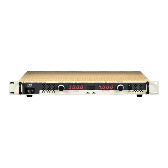
- Page 10 LIST OF FIGURES FIGURE TITLE PAGE KLP Series Power Supply ..........................vi KLP Operating Regions..........................1-2 KLP Series Power Supply, Mechanical Outline Drawing ................1-6 KLP Series, Front Panel Controls and Indicators..................2-1 KLP Series, Rear Panel Switch and Connectors ..................2-3 Remote Sensing............................
- Page 11 LIST OF TABLES TABLE TITLE PAGE Model Parameters ............................1-2 KLP Specifications ............................1-3 Equipment Supplied ............................1-10 Accessories ..............................1-11 Safety Symbols ............................1-11 Controls, and Indicators ..........................2-1 Analog I/O Switch Functions ........................2-2 IEEE 488 Port Connector (J4) Pin Assignments ..................2-4 RS232 Port Connector (J3) Pin Assignments [-1200 Models Only] ............2-4 LAN Port Connector (J7) Pin Assignments [-1.2K Models Only] ..............2-5 Control Input Terminal block Assignments ....................2-5 Analog I/O Connector (J2) Pin Assignments ....................2-5...
- Page 12 FIGURE 1-1. KLP SERIES POWER SUPPLY KLP031308...
-
Page 13: Section 1 - Introduction
This manual contains instructions for the installation, operation and service of the KLP series of 1200W output power, stabilized voltage or current, d-c power supplies manufactured by KEPCO, Inc., Flushing, New York, U.S.A. WARNING DANGEROUS AND LETHAL POTENTIALS ARE PRESENT,... -
Page 14: Klp Operating Regions
FIGURE 1-2. KLP OPERATING REGIONS TABLE 1-1. MODEL PARAMETERS Rated Maximum Minimum Rated Maximum Ripple and Efficiency Model number Voltage current for programmable Current voltage for noise @115 Va-c Range rated voltage current Range rated current KLP 10-150- 0-10V 120A@10V 3.2A 0-150A 8V@150A... -
Page 15: Klp Specifications
TABLE 1-2. KLP SPECIFICATIONS SPECIFICATION RATING/DESCRIPTION CONDITION/COMMENT INPUT CHARACTERISTICS nominal 110-240 Va-c Single Phase. a-c voltage range 100-255 Va-c Wide Range; contact factory for opera- tion to 265V a-c. d-c voltage range 125-420 Vd-c No regulatory agency approval. nominal range 50-60 Hz Frequency maximum... - Page 16 TABLE 1-2. KLP SPECIFICATIONS (Continued) SPECIFICATION RATING/DESCRIPTION CONDITION/COMMENT GENERAL (ENVIRONMENTAL) SPECIFICATIONS Temperature operating -20 to +50 deg C Rated load. Derate at 25W per °C between 50 and 70°C. storage -40 to +85 deg C Cooling 3 internal d-c fans exhaust to the rear Humidity 0 to 95% RH...
- Page 17 TABLE 1-2. KLP SPECIFICATIONS (Continued) SPECIFICATION RATING/DESCRIPTION CONDITION/COMMENT PROGRAMMING CHARACTERISTICS - ANALOG Analog remote control selection Activate with jumper at analog program- Recognized during power up. ming connector isolation Safety Extra Low Voltage (SELV) Analog Input Update Rate 2Hz (0.5 Second) Applies to program- Analog input voltage digitized (12-bit ming by voltage/ resistance and read- resolution), optically isolated, then pro-...
-
Page 18: Klp Series Power Supply, Mechanical Outline Drawing
R\DWG\MECH\3010266 FIGURE 1-3. KLP SERIES POWER SUPPLY, MECHANICAL OUTLINE DRAWING (SHEET 1 OF 2) KLP 031308... - Page 19 FIGURE 1-3. KLP SERIES POWER SUPPLY, MECHANICAL OUTLINE DRAWING (SHEET 2 OF 2) KLP 031308...
-
Page 20: Features
FEATURES 1.4.1 LOCAL CONTROL Two front panel rotary encoders allow adjustment of voltage and current setpoints and limits. Operating mode of the power supply is indicated by lighting either a green (Constant Voltage) or amber (Constant Current) LED. The output can be enabled or disabled by the front panel DC OUTPUT switch;... -
Page 21: Overvoltage/Overcurrent Protection
1.4.4 OVERVOLTAGE/OVERCURRENT PROTECTION Overvoltage and Overcurrent protection values can be individually programmed. If the output voltage/current exceeds the overvoltage/overcurrent protection value, the protection circuit latches the output off, flashes an overvoltage (OVP) or overcurrent (OCP) error message on the status display and sets a status bit that can be retrieved through the RS 232 [-1200 Models only], LAN [-1.2K Models only], or GPIB port. -
Page 22: Internal Relay
There are no operator serviceable parts inside the case. Service must be referred to authorized personnel. Using the power supply in a manner not specified by Kepco. Inc. may impair the pro- tection provided by the power supply. Observe all safety precautions noted throughout this man- ual. -
Page 23: Accessories
Mates with NEMA 5-15R receptacle (see adjacent figure). Supports restricted load power over mains voltage range of 100-136V a-c (contact Kepco Sales Engineering for details). Line Cord Set (250V/15A) 2.5m long cord set, provides for source power NEMA 6-15R 118-1137 connection. -
Page 25: Section 2 - Installation
SECTION 2 - INSTALLATION UNPACKING AND INSPECTION This instrument has been thoroughly inspected and tested prior to packing and is ready for operation. After careful unpacking, inspect for shipping damage before attempting to operate. Perform the preliminary operational check as outlined in PAR 2.5. If any indication of damage is found, file an immediate claim with the responsible transport service. -
Page 26: Analog I/O Switch Functions
TABLE 2-1. CONTROLS, AND INDICATORS (CONTINUED) CONTROL OR FUNCTION INDICATOR DC AMPERES Four-digit LED display that shows current settings: display a. Shows actual output current (PAR.3.2.7). b. Shows current set point or overcurrent limit when function selected (PAR. 3.2.7.2). c. Shows GPIB address (PAR. 3.2.9), baud rate (PAR. 3.2.10). d. -
Page 27: Klp Series, Rear Panel Switch And Connectors
FIGURE 2-2. KLP SERIES, REAR PANEL SWITCH AND CONNECTORS KLP-HV 031308... -
Page 28: Ieee 488 Port Connector (J4) Pin Assignments
TABLE 2-3. IEEE 488 PORT CONNECTOR (J4) PIN ASSIGNMENTS SIGNAL NAME FUNCTION I/O Line I/O Line I/O Line I/O Line End or Identify Data Valid NRFD Not Ready for Data NDAC Not Data Accepted Interface Clear Service Request Attention SHIELD Shield I/O Line I/O Line... -
Page 29: Lan Port Connector (J7) Pin Assignments [-1.2K Models Only]
TABLE 2-5. LAN PORT CONNECTOR (J7) PIN ASSIGNMENTS [-1.2K MODELS ONLY] SIGNAL NAME FUNCTION Transmit + TX– Transmit – NOT USED NOT USED NOT USED NOT USED Receive + RX– Receive – TABLE 2-6. CONTROL INPUT TERMINAL BLOCK ASSIGNMENTS TERMINAL FUNCTION Positive output monitor connection (TB5) (see PAR. -
Page 30: Source Power Requirements
SOURCE POWER REQUIREMENTS This power supply operates with the installed circuit breaker from either d-c or single phase a-c mains power over the voltage and frequency ranges specified in Table 1-2 without adjustment or modification. COOLING The power devices used within the power supply are maintained within their operating tempera- ture range by means of internal heat sink assemblies cooled by three internal (d-c type) cooling fans. -
Page 31: Installation
and DC AMPERES reads 19.2.) • Then the status display reads SET (setpoint mode), the DC VOLTS display reads 0 Volts, the DC AMPERES display reads minimum Amperes (see Note 1, below). NOTES: 1. A minimum programmed current (actual value depends on model) is required to ensure proper operation of the power supply under all load conditions. -
Page 32: Safety Grounding
It is the user's responsibility to ensure that all applicable local codes for source power wiring are met. Kepco also makes a variety of prefabricated safety line cord sets available for connecting KLP to source power via conven- tional box-mounted receptacles. -
Page 33: D-C Output Grounding
It is hoped that the preceding paragraphs will be of some assistance in most cases. For help in special applications or difficult problems, consult directly with Kepco's Application Engineering Depart- ment. -
Page 34: Power Supply/Load Interface
2.7.4 POWER SUPPLY/LOAD INTERFACE The general function of a voltage or current stabilized power supply is to deliver the rated output quantities to the connected load. The load may have any conceivable characteristic: it may be fixed or variable, it may have predominantly resistive, capacitive or inductive parameters; it may be located very close to the power supply output terminals or it may be a considerable distance away. -
Page 35: Series Operation
Figure 2-4 shows a series connection of two KLP power supplies using remote sensing. Kepco strongly recommends that series applica- tions employ master/slave control (available on -1200 Models only) as described in PAR’s. 2.7.8 and 3.2.11. -
Page 36: Series Connection Using Remote Sensing
2.7.6 FIGURE 2-4. SERIES CONNECTION USING REMOTE SENSING FIGURE 2-5. PARALLEL CONNECTIONS USING REMOTE SENSING 2-12 KLP-HV 031308... -
Page 37: Load Sharing
2.7.7.1 LOAD SHARING When operating two or more power supplies in parallel, either for capacity or redundancy, it is desirable to distribute the load equally among all of the power supplies in order to improve per- formance, reduce stress and increase reliability. KLP power supplies incorporate active circuitry which forces multiple power supplies wired in parallel to share load current, both in voltage- and current-mode regulation. -
Page 38: Analog I/O Connections
2.7.9 ANALOG I/O CONNECTIONS The Analog I/O Port connector, located on the rear panel of the KLP power supply (see Figure 2-2), provides access for all analog programming inputs and status signal outputs. In addition, an external trigger input is available for use with SCPI *TRG and TRIG commands. Refer to Table 2-7 for analog I/O programming signal pin assignments and descriptions. -
Page 39: Rs 232 Connections [-1200 Models Only]
2.8.2 RS 232 CONNECTIONS [-1200 MODELS ONLY] Communications between KLP, considered data terminal equipment (DTE), and data communi- cations equipment (DCE), e.g. a modem, requires a patch cable, or one with a pin-for-pin rela- tionship between terminating connectors. A null modem cable is necessary for nearly all applications, with the exception of those in which the RXD and TXD line transposition is accom- plished via external hardware (e.g. -
Page 41: Section 3 - Operation
SECTION 3 - OPERATION GENERAL This section explains how to operate the KLP Power Supply. Series KLP feature three modes of operation: • Local Mode: This is the default operating mode, providing full access to all programming and readback functions via front panel displays, controls, and indicators (see PAR. 3.2). •... -
Page 42: Power-Up Built-In Test Error Codes
• For -1.2K Models, the LAN indicator blinks rapidly during initialization. If an IP address is found, it stays on without blinking. If an IP address is not found, the LAN indicator stays off. • If any fault is configured for AUTO recovery (see PAR. 3.2.13.5.2), the status display flashes AUTO for one second. -
Page 43: Setting Local/Remote Mode
3.2.2 SETTING LOCAL/REMOTE MODE LOCAL MODE. When the power supply is turned on, it is automatically set to Local mode as long as Analog I/O port pin 12 is not grounded. In local mode the Status display is normally blank. DIGITAL REMOTE MODE. -
Page 44: Enabling/Disabling Output Power
NOTE: If the front panel is unlocked by SCPI command, the unit will be set to Remote with Local Lockout when it is turned on again. Set ANALOG I/O DIP switch posi- tion 5 to OFF to disable Remote with Local Lockout. 3.2.3 ENABLING/DISABLING OUTPUT POWER When the power supply is turned on, the output is automatically disabled (DC OUTPUT LED is... -
Page 45: Defining A Virtual Model
3.2.6 DEFINING A VIRTUAL MODEL The virtual model is defined by establishing a maximum programmable voltage and current for the unit within the 1200W power limitation and the maximum voltage and current ratings listed in Table 1-1. Once established, the unit will not accept programmed values beyond these values whether from the front panel in local mode, or from the digital (GPIB, RS232, or LAN) or analog input ports in remote mode. -
Page 46: Setting Voltage Or Current
imum output power at 1200 Watts. Maximum current shown on DC AMPERES display is automatically limited to 1200W maximum. 5. Press DC OUTPUT switch to accept virtual model settings. The unit displays done, then resets and repeats the power on sequence (see PAR. 3.2.1). NOTE: Accepting a new virtual model resets the setpoints to zero Volts and minimum Amperes, resets the OVP and OCP values and, if DIP switch position 3 is enabled, clears stored setpoints of voltage and current as described above. -
Page 47: Last Setting Recall
2. In the setpoint mode, both coarse (rotate the control) and fine (rotate while pressing control in) adjustment is available. The coarse adjustment is approximately 100X the fine adjust- ment resolution. Setpoint adjust can be done with output either on or off, however the output can not be enabled while setpoint is active (See PAR. -
Page 48: Changing Gpib Address
play shows PROT. The DC VOLTS and DC AMPERES displays show the corresponding overvoltage and overcurrent protection setpoints while the PROTECT switch is held in. 2. To change the values, operate the corresponding adjustment control while holding the PRO- TECT switch in. When the PROTECT switch is released, the protection values showing in the DC VOLTS and DC AMPERES displays are entered as the new protection values. -
Page 49: Configure Power Supply As Master [-1200 Models Only]
3.2.11.1 CONFIGURE POWER SUPPLY AS MASTER [-1200 MODELS ONLY] 1. Turn power on. If the unit comes up in setpoint mode (see PAR. 3.2.4), tap either the CUR- RENT or VOLTAGE controls to take the unit out of setpoint mode (status display goes from SET to blank). -
Page 50: Operating The Master/Slave Configuration [-1200 Models Only]
• The DC VOLTS display shows the number assigned to the unit (1 = master, 2 or above = slave). • The DC AMPERES display shows the maximum number of units in the configuration. • The factory default is standalone operation (DC VOLTS and DC AMPERES show 1). 4. -
Page 51: Lan Interface Configuration [-1.2K Models Only]
• If E241 (hardware error) is showing in the status display, check the master and/or slave setup. If necessary, use FUNCTION switch to enter the M/S menu to change the config- uration as described above. • If there is no communication between units for approximately 10 seconds, all units will turn off their output and the status display will flash E241 (hardware error), then xOFy where x = unit number and y = total number of units, and finally the serial/parallel config- uration setting SERI or PARA. -
Page 52: Utility Function
the address, press DC OUTPUT switch, then rotate VOLTAGE control to change 192._ or CURRENT control to change 168._, then press DC OUTPUT switch to save. • IP2 - Shows second half of IP address (e.g., for IP address 192.168.000.200 the DC VOLTS display shows _000. -
Page 53: Display System Firmware Version
lems (see KLP Developer’s Guide). • CAL - Display last calibration date and/or begin Calibration (see PAR. 3.2.13.7) • RTN - Exit any submenu and return to previous menu 3.2.13.1 DISPLAY SYSTEM FIRMWARE VERSION Enter UTIL menu (see PAR. 3.2.13, steps 1 through 3) and rotate either VOLTAGE or CUR- RENT control until status display reads VERS. - Page 54 after a user-programmable delay, the relay energizes upon a transition from constant voltage (CV) to constant current (CC) mode. C->V: relay energizes immediately upon detection of a system (fatal) error and, after a user-programmable delay, the relay energizes upon a transition from constant current (CC) to constant voltage (CV) mode.
-
Page 55: Quick Boot
NOTE: If a SYSTem:SECurity:IMMediate command is issued, the above relay control settings are reset to the factory default: FLT - NORM. 3.2.13.4 QUICK BOOT Enter UTIL menu (see PAR. 3.2.13, steps 1 through 3) and rotate either VOLTAGE or CUR- RENT control until status display reads QkBT - Quick Boot. -
Page 56: 3.2.13.5.2 Fault Recovery Configuration
3.2.13.5.2 FAULT RECOVERY CONFIGURATION The KLP allows the user to control how the unit recovers from faults, and allows different responses for different faults. This function is password-protected. The three recovery options are PROT, SAFE and AUTO. • PROTected - When a fault configured as PROT is detected, the output is disabled. Recovery requires that the user turn the unit off and wait five seconds before turning the unit on. -
Page 57: Analog Input Full Scale Calibration
1. Enter UTIL menu (see PAR. 3.2.13, steps 1 through 3) and rotate either VOLTAGE or CUR- RENT control until status display reads SYST, then tap DC OUTPUT switch. Rotate either VOLTAGE or CURRENT control to until the status display reads RCOV. The DC VOLTS and DC AMPERES displays show a series of bars that give a snapshot pic- ture of the recovery configuration as defined in Figure 3-1. -
Page 58: Calibration
• ON (enabled) NOTE: Kepco strongly recommends the XON XOFF method for data transfer via RS 232 protocol for all Kepco products. If this method is not selected, it is the user's responsibility to ensure completion of any response by the power supply prior to issuance of subsequent commands. -
Page 59: Additional Functions Not Available From The Front Panel
Kepco provides three instrument drivers, IVI-COM, LabView G and VXI plug&play which sim- plify programming of the KLP power supply via the digital interfaces. These drivers are described in the KLP Developer’s Guide and can be downloaded from the Kepco web site at: http://www.kepcopower.com/drivers/ 3.3.3... -
Page 60: Finding Kepco Power Supplies On The Lan [-1.2K Models Only]
The PSfind utility is supplied on the CD that comes with the unit, or can be downloaded from the Kepco web site at www.kepcopower.com/drivers. This utility finds all operational Kepco power supplies connected to the LAN and then shows the pertinent addresses of the models found. To run the utility from your PC go to \utilities on the CD. -
Page 61: Launch Web Interface [-1.2K Models Only]
KLP can not be restored until the present browser window is closed and a new window is opened. Although most current browsers will work, Kepco recommends the following as fully supported: IE 5.5 and higher, Netscape 6 and higher and Firefox 1.0 and higher. Popup blocking must be disabled and Javascript must be enabled for proper operation. -
Page 62: Instrument Configuration Using Web Interface [-1.2K Models Only]
The KLP Instrument Home page identifies the unit which has been accessed, including Manu- facturer, Instrument, Description, Serial Number, Calibration Date, LXI Software Revision, LXI Class, LXI Version, Hostname, MAC Address and TCP/IP Address. Click the HELP box at the left of the screen for detailed explanations of each. -
Page 63: Lan Configuration Using Web Interface [-1.2K Models Only]
3.3.6.4 LAN CONFIGURATION USING WEB INTERFACE [-1.2K MODELS ONLY] Click on CONFIGURE LAN at the left to view the LAN Configuration page (Figure 3-6). The parameters that can be configured from this page are Host Name (DHCP), Description, IP Address, Subnet Mask address, Default Gateway Address, and DNS Server Address. Separate checkboxes allow enabling of DHCP, AUTOIP and PING. -
Page 64: Operating The Unit Using Web Interface [-1.2K Models Only]
FIGURE 3-6. WEB INTERFACE CONFIGURE LAN PAGE 3.3.6.5 OPERATING THE UNIT USING WEB INTERFACE [-1.2K MODELS ONLY] To operate the unit, click the OPERATE INSTRUMENT box at the left. A simulated front panel at the top of the screen shows 1) output voltage and current, 2) CV or CC if the unit is in con- stant voltage or constant current mode, respectively (** is displayed if the output is off, meaning the unit is in neither CV nor CC mode), and 3) whether the output is on or off. -
Page 65: Changing The Output [-1.2K Models Only]
FIGURE 3-7. WEB INTERFACE OPERATE INSTRUMENT PAGE 3.3.6.5.1 CHANGING THE OUTPUT [-1.2K MODELS ONLY] The Output dialog box opens when the OPERATE INSTRUMENT page is first opened, or when OUTPUT is clicked (see Figure 3-7). To set output voltage or current, enter the values and click SET. -
Page 66: Save/Recall Dialog Box
ture. These settings are cleared when a calibration is performed. Click SAVE/RECALL to open the Save/Recall Dialog Box (Figure 3-9). FIGURE 3-9. SAVE/RECALL DIALOG BOX NOTE: When the SAVE/RECALL tab is initially selected, parameters for all locations appear as empty even when there are values stored from previous sessions. Click the Pre- view button first to avoid overwriting existing data. -
Page 67: Resetting The Unit (*Rst) [-1.2K Models Only]
3.3.6.5.4 RESETTING THE UNIT (*RST) [-1.2K MODELS ONLY] Click *RST button to reset power supply to the power on default state: setpoints to zero Volts and minimum Amperes (see NOTE, PAR. 3.2.1, step 3, and Table 1-2), and output set to OFF, except that if last setting recall (PAR. -
Page 68: Setting Virtual Model [-1.2K Models Only]
Clearing the List. Once a step has been added, it can not be changed and can only be deleted by pressing the Clear List button to start over. In addition, performing any of the following oper- ations will also clear the list: changing overcurrent or overvoltage PROTECTION settings, unit RESET (clicking *RST), changing VIRTUAL MODEL settings and exiting the OPERATE INSTRUMENT page. -
Page 69: Remote Programming Using Analog Signals
Setting a new virtual model resets the setpoints to zero Volts and minimum Amperes and resets the OVP and OCP values to 120% of virtual model maximum. A minimum programmed current is required to ensure proper operation of the power supply under all load conditions. Pro- grammed current is automatically set to be at least the minimum current (actual value depends on model, see Table 1-1). -
Page 70: Programming With External Resistance
3.4.2 PROGRAMMING WITH EXTERNAL RESISTANCE Figure 3-14 is a simplified diagrams of the KLP showing the switch configuration and external connections required for analog programming using an external resistance. 1. Overvoltage and Overcurrent settings must be established via either local programming or digital remote programming prior to initiating Analog Remote programming. -
Page 71: Programming With External Voltage
3.4.3 PROGRAMMING WITH EXTERNAL VOLTAGE Figure 3-15 is a simplified diagrams of the KLP showing the switch configuration and external connections required for analog programming using an external voltage. 1. Virtual Model (PAR. 3.2.6) and Overvoltage and Overcurrent settings (PAR. 3.4.4) must be established via either local programming or digital remote programming prior to initiating Analog Remote programming. -
Page 72: Changing Overvoltage Or Overcurrent Protection Values In Analog Programming Mode
3.4.4 CHANGING OVERVOLTAGE OR OVERCURRENT PROTECTION VALUES IN ANALOG PROGRAMMING MODE Overvoltage and overcurrent values can not be changed using analog remote programming; this can only be done by issuing a command via the GPIB or RS232 port, or via local mode from the front panel (enter local mode by pressing the VOLTAGE and CURRENT adjustment con- trols at the same time, then see PAR. -
Page 73: Section 4 - Calibration
SECTION 4 - CALIBRATION GENERAL This section contains the calibration instructions for the Power Supply. It is recommended that the user be familiar with Local Mode operation (PAR.3.2) before calibrating the unit. A full calibration consist of a voltage calibration and a current calibration. Both voltage and cur- rent calibrations consist of a zero and a full scale calibration. -
Page 74: Calibration Using Front Panel Controls In Local Mode
CALIBRATION USING FRONT PANEL CONTROLS IN LOCAL MODE For voltage calibration all loads must be disconnected and the sense terminals connected to the corresponding output terminals. The digital voltmeter will be connected to the output of the power supply. For current calibration after disconnecting all loads an appropriate shunt resistor will be connected across the output terminals and the digital voltmeter will be connected across the sense terminals of the shunt resistor. -
Page 75: Current Calibration (Local)
3. Tap the DC OUTPUT switch to accept the value. The status display then reads OUTV. Con- nect the DVM to ANALOG I/O PORT J2, pin 13 (M–) and pin 6 (M+). Rotate the VOLTAGE control to increase or decrease the output voltage until the DVM reads as close as possible to 10V. -
Page 76: Calibration Exit (Local)
GPIB cards from suppliers such as National Instruments and Hewlett-Packard. The following calibration procedure uses the “soft” front panel which is part of the VXI plug&play driver for the KLP which can be downloaded from the Kepco website at: www.kepcopower.com/ drivers/ or from the supplied CD. -
Page 77: Calibration Window
Unzip the files and doubleclick on setup.exe to install the driver. The Kepco\klp folder will be added to the Start - Programs folder. Doubleclick KLPCTRL.exe to run the program, and refer to the KLP Developer’s Guide in the Kepco\klp folder for details about using the soft front panel. -
Page 78: Voltage Calibration (Vxi Plug&Play Driver Demo)
7. Use the computer keyboard to enter the password in the text box displaying the word PASS- WORD, then press the ENTER key. 8. If password is correct, the status display on the VXI main panel reads CAL and the buttons on Calibration Screen (Figure 4-1) are enabled (highlighted). -
Page 79: Current Calibration (Vxi Plug&Play Demo)
3. Click the PRESS TO ACCEPT button to accept the value. The status display then reads OUTV. Connect to DVM (+) to Analog I/O Port J2, pin 6 and DVM (–) to pin 13. Click the “+” button to increase and the “–-“ button to decrease the output voltage until the DVM reads as close as possible to 10V. -
Page 80: Analog Reference Calibration (Vxi Plug&Play Demo)
4. Click the PRESS TO ACCEPT button to accept the value. The status display reads CMAX. Click the “+” button to increase and the “–“ to decrease the output current until the DVM reads as close as possible to maximum rated current (Calculate current as follows: I (Amperes) = DVM reading (Volts) / Shunt Resistance (Ohms). -
Page 81: Calibration Exit (Vxi Plug&Play Demo)
2. The status display reads INPC. Connect the reference voltage used to define full scale out- put current as described in PAR 3.4. 3. When the reference voltage is at the desired value, click the PRESS TO ACCEPT button to accept the value. -
Page 82: Restoring Prior Calibration Values
Working. Each time the unit is calibrated, the Working values are moved to Previous, and the new calibration values are stored in Working. It is possible to replace the Working calibration values with either the Previous or the Factory calibration values; contact Kepco Sales Engineer- ing for details. -
Page 83: Klp Installation/Operation Summary
4. Connect power supply to power source using one of the following: See PAR. 2.7.2 for additional information. • Use standard NEMA line cord set from Kepco (see Table 1-4) or customized line cord using user-wireable mating connector (supplied) in conjunction with user-selected line cord or discrete wiring as applicable. - Page 84 How do I view/change the virtual model settings? See PAR. 3.2.6 for description of virtual model. If status shows SET, exit set- point mode (tap either knob once). Use thin tool to press FUNCTION once; status reads VIRT. VOLTS and AMPS displays show the maximum voltage and current of the present virtual model.
Need help?
Do you have a question about the KLP 10-150-1200 and is the answer not in the manual?
Questions and answers