Sign In
Upload
Manuals
Brands
KEPCO Manuals
Power Supply
KLP 10-150
KEPCO KLP 10-150 Manuals
Manuals and User Guides for KEPCO KLP 10-150. We have
2
KEPCO KLP 10-150 manuals available for free PDF download: User Manual, Quick Start Manual
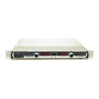
KEPCO KLP 10-150 User Manual (94 pages)
KLP SERIES, 1200 WATT PROGRAMMABLE POWER SUPPLY
Brand:
KEPCO
| Category:
Power Supply
| Size: 2.23 MB
Table of Contents
Power Supply
1
Declaration of Conformity
3
Safety Instructions
5
Table of Contents
7
Section 1 - Introduction
13
Scope of Manual
13
General Description
13
Options
14
Rapid Output Discharge Circuit (RODC) Option (R Suffix)
14
Specifications
14
Rapid Output Discharge Circuit Improvement in Output Response Time
14
KLP Operating Regions
15
Model Parameters
15
KLP Specifications
16
Physical Characteristics
18
KLP Series Power Supply, Mechanical Outline Drawing
20
Features
22
Local Control
22
Remote Control
22
Digital Programming
22
Analog Programming
22
Digital Calibration
22
Overvoltage/Overcurrent Protection
23
User-Defined Voltage/Current Limits (Virtual Models)
23
Storage of User-Programmed Active Settings
23
User-Programmed Sequences
23
Last Setting Recall
23
Built-In Protection
23
Internal Relay
24
Master/Slave Control [Standard Models Only]
24
Equipment Supplied
24
Accessories
24
Safety
24
Accessories
25
Safety Symbols
25
Section 2 - Installation
27
Unpacking and Inspection
27
Terminations and Controls
27
Front Panel Controls and Indicators
27
KLP Series, Front Panel Controls and Indicators
27
Rear Panel Connectors and Switches
28
Analog I/O Switch Functions
28
KLP Series, Rear Panel Switch and Connectors
29
IEEE 488 Port Connector (J4) Pin Assignments
30
RS 232 Port Connector (J3) Pin Assignments [Standard Models Only]
30
LAN Port Connector (J7) Pin Assignments [E-Series Models Only]
31
Control Input Terminal Block Assignments
31
Analog I/O Connector (J2) Pin Assignments
31
Source Power Requirements
32
Cooling
32
Preliminary Operational Check
32
Installation
33
Rack Mounting
33
Wiring Instructions
33
Safety Grounding
34
Source Power
34
Current Rating
34
Connections
34
Input Current Service Rating and Conductor Sizes
34
D-C Output Grounding
35
Power Supply/Load Interface
36
Load Connection - General
36
Local Sensing/Remote Sensing Select
36
Series Operation
37
Parallel Operation
37
Remote Sensing
37
Series Connection Using Remote Sensing
38
Parallel Connections Using Remote Sensing
38
Load Sharing
39
Master/Slave Configurations [Standard Models Only]
40
Analog I/O Connections
40
Digital Connections
41
GPIB Connections
41
RS 232 Connections [Standard Models Only]
41
LAN Connections [E-Series Models Only]
41
Section 3 - Operation
43
General
43
Local Mode Operation
43
Turning the Power Supply on
43
Power-Up Built-In Test Error Codes
44
Setting Local/Remote Mode
45
Remote with Local (Front Panel) Lockout
46
Menu Structure
46
Setting VOLTAGE and CURRENT Control Coarse/Fine Preference
46
Enabling/Disabling Output Power
47
Function Switch Menu Structure
47
Enabling/Disabling the Output Using Remote Inhibit
48
Checking Voltage/Current Setpoints
49
Password Protected Functions
49
Defining a Virtual Model
49
Setting Voltage or Current
50
Real-Time Voltage/Current Adjustment
51
Setpoint Adjustment
51
Last Setting Recall
51
Viewing/Changing Overvoltage or Overcurrent Protection Values
52
Changing GPIB Address
52
Changing RS 232 Baud Rate [Standard Models Only]
53
Setting up Master/Slave Configurations [Standard Models Only]
53
Configure Power Supply as Slave [Standard Models Only]
53
Configure Power Supply as Master [Standard Models Only]
54
Operating the Master/Slave Configuration [Standard Models Only]
55
Restoring the Master/Slave Configuration to Standalone Operation [Standard Models Only]
56
LAN Interface Configuration [E-Series Models Only]
56
Unit Configuration
58
Utility Function
58
Internal Relay Control
59
Quick Boot
60
System Configuration Functions
61
3.2.17.3.1 Remote Inhibit Polarity
61
3.2.17.3.2 Fault Recovery Mode
61
Fault Recovery Configuration
62
Analog Output Full Scale Calibration
63
Fault Recovery Configuration Display
63
Analog Input Full Scale Calibration
64
Calibration
64
Remote Mode Programming Using Digital Interfaces
64
Factory Default Settings
64
GPIB Factory Defaults
64
RS 232 Factory Defaults [Standard Models Only]
65
LAN Factory Defaults [E-Series Models Only]
65
Additional Functions Not Available from the Front Panel
66
Remote Programming Using the IVI-COM Instrument Driver
66
Remote Programming Using the Labview G Instrument Driver
66
Remote Programming Using the VXI Plug&Play Instrument Driver
66
Remote Programming Using the Web Interface [E-Series Models Only]
66
Troubleshooting LAN Communication Problems
67
Finding Kepco Power Supplies on the LAN [E-Series Models Only]
67
Launch Web Interface [E-Series Models Only]
68
PS Find Screen
68
Instrument Configuration Using Web Interface [E-Series Models Only]
69
Web Interface Home Page (Unit Description)
69
LAN Configuration Using Web Interface [E-Series Models Only]
70
Web Interface Configure Instrument Page
70
Web Interface Configure LAN Page
71
Operating the Unit Using Web Interface [E-Series Models Only]
72
Changing the Output [E-Series Models Only]
72
Changing Protection [E-Series Models Only]
72
Using Save and Recall [E-Series Models Only]
72
Web Interface Operate Instrument Page
73
Protection Dialog Box
73
Save/Recall Dialog Box
73
Resetting the Unit (*RST) [E-Series Models Only]
74
Using a List (User-Programmed Sequences) [E-Series Models Only]
74
Reset Dialog Box
74
List Dialog Box
75
Setting Virtual Model [E-Series Models Only]
76
Adding Multiple Steps (Ramps) to List
76
Remote Programming Using Analog Signals
77
Virtual Model Dialog Box
77
Programming with External Resistance
78
Current Using Resistance
78
Analog Programming of Output Voltage or Current Using Resistance
78
Programming with External Voltage
79
Analog Programming of Output Voltage or Current Using Voltage
79
Changing Overvoltage or Overcurrent Protection Values in Analog Programming Mode
80
Section 4 - Calibration
81
General
81
Equipment Required
81
Calibration Using Front Panel Controls in Local Mode
82
Analog Port Wiring for Calibration
82
Voltage Calibration (Local)
83
Current Calibration (Local)
83
External Calibration (Local)
84
Calibration Exit (Local)
84
Calibration Using VXI Plug&Play Driver
85
Voltage Calibration (VXI Plug&Play Driver Demo)
86
Calibration Window
86
Current Calibration (VXI Plug&Play Demo)
87
Voltage Calibration Window
87
Current Calibration Window
88
Analog Reference Calibration (VXI Plug&Play Demo)
89
Analog Reference Calibration Window
89
Calibration Exit (VXI Plug&Play Demo)
90
Changing the Calibration Password
90
Factory Default Unit Passwords
90
Restoring Prior Calibration Values
91
Klp Installation/Operation Summary
93
Advertisement
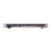
KEPCO KLP 10-150 Quick Start Manual (12 pages)
Brand:
KEPCO
| Category:
Power Supply
| Size: 0.8 MB
Table of Contents
Table of Contents
1
Description
2
Unpacking
2
Equipment Supplied
2
Accessories
3
Safety
3
Preliminary Operational Check
4
Installation
5
Input Connections
5
Load Connections
5
Local Sensing (Factory Default)
6
Remote Sensing Select
6
Analog I/O Connections
7
GPIB Connections
7
RS 232 Connections (Standard Models)
7
LAN Connections (E-Series Models)
7
Operation
7
Turning the Power Supply on
7
Enabling/Disabling Output Power
8
Checking or Changing Voltage/Current Setpoints
8
Virtual Model Setting
8
Setting Voltage or Current
9
Last Setting Recall
10
Viewing/Changing Overvoltage or Overcurrent Protection Values
10
Klp Outline Dimensions
11
Http://Www.kepcopower.com " Email: Hq@Kepcopower.com
12
Advertisement
Related Products
KEPCO KLP 10-150-(2)
KEPCO KLP 10-150-3
KEPCO KLP 10-150-1200
KEPCO KLP 10-150-1.2K
KEPCO KLP 10-150-2
KEPCO KLP 150-16-(2)
KEPCO KLP 150-16-3
KEPCO KLP 150-16-1200
KEPCO KLP 150-16-1.2K
KEPCO KLP 150-4
KEPCO Categories
Power Supply
Adapter
Battery Charger
Recording Equipment
Protection Device
More KEPCO Manuals
Login
Sign In
OR
Sign in with Facebook
Sign in with Google
Upload manual
Upload from disk
Upload from URL