Thermal Dynamics Pak Master 50 Instruction Manual
Air plasma cutting power supply
Hide thumbs
Also See for Pak Master 50:
- Operating manual (44 pages) ,
- Operating manual (48 pages) ,
- Service manual (88 pages)
Table of Contents
Troubleshooting

Subscribe to Our Youtube Channel
Related Manuals for Thermal Dynamics Pak Master 50


Summary of Contents for Thermal Dynamics Pak Master 50
-
Page 1: Power Supply
® A THERMADYNE Company ® Air Plasma Cutting Power Supply The System Includes: ® • Pak Master 50 Power Supply ® • PCH/M-35 Smart Torch with Leads • Optional Input Power Cable • Work Cable with Clamp Instruction Manual Manual No. 0-2470... - Page 2 Read and understand this entire Instruction Manual and your WARNING employer’s safety practices before installing, operating, or servicing the equipment. While the information contained in this Instruction Manual WARNING represents our best judgement, Thermal Dynamics Corporation assumes no liability for its use. ®...
-
Page 3: Table Of Contents
TABLE OF CONTENTS SECTION 1: GENERAL INFORMATION ..................1 1.01 Notes, Cautions and Warnings ............... 1 1.02 Important Safety Precautions ................. 1 1.03 Publications ....................2 1.04 Note, Attention et Avertissement ..............3 1.05 Precautions De Securite Importantes ............. 3 1.06 Documents De Reference ................ - Page 4 TABLE OF CONTENTS (continued) SECTION 6: PARTS LIST ......................69 6.01 ORDERING INFORMATION ................ 69 6.02 SYSTEM COMPONENTS AND ACCESSORIES ......... 70 6.03 FRONT PANEL COMPONENTS ..............71 6.04 REGULATOR/SOLENOID ASSEMBLY ............72 6.05 BASE PANEL COMPONENTS ..............73 6.06 CHASSIS COMPONENTS ................74 6.07 REAR PANEL COMPONENTS ..............
-
Page 5: Section 1: General Information
• Use an air-supplied respirator if ventilation is not SECTION 1: adequate to remove all fumes and gases. GENERAL INFORMATION • The kinds of fumes and gases from the plasma arc depend on the kind of metal being used, coatings on the metal, and the different processes. -
Page 6: Publications
• Keep helmet and safety glasses in good condition. Replace lenses when cracked, chipped or dirty. FIRE AND EXPLOSION • Protect others in the work area from the arc rays. Use protective booths, screens or shields. Fire and explosion can be caused by hot slag, sparks, or •... -
Page 7: Note, Attention Et Avertissement
12. CSA Standard W117.2, CODE FOR SAFETY IN 1.05 Precautions De Securite WELDING AND CUTTING, obtainable from the Ca- Importantes nadian Standards Association, Standards Sales, 178 Rexdale Boulevard, Rexdale, Ontario, Canada M9W 13. NWSA booklet, WELDING SAFETY BIBLIOGRA- AVERTISSEMENT PHY obtainable from the National Welding Supply Association, 1900 Arch Street, Philadelphia, PA 19103 L’OPÉRATION ET LA MAINTENANCE DU 14. - Page 8 • Utilisez un équipement spécial tel que des tables de • Prévoyez une veille d’incendie lors de tout travail coupe à débit d’eau ou à courant descendant pour dans une zone présentant des dangers d’incendie. capter la fumée et les gaz. •...
-
Page 9: Documents De Reference
• Pour des renseignements sur la manière de tester le 9. Norme 70 de la NFP A, CODE ELECTRIQUE NA- bruit, consultez l’article 1, page 5. TIONAL, disponible auprès de la National Fire Pro- tection Association, Batterymarch Park, Quincy, MA 1.06 Documents De Reference 02269 10. -
Page 10: Declaration Of Conformity
Thermal Dynamics has been manufacturing products that perform in a safe manner for more than 30 years and will continue to achieve excellence in our area of manufacture. Manufacturers responsible representative: David Ashworth Vice President & Managing Director Thermadyne Europe Chorley England. GENERAL INFORMATION... -
Page 11: Statement Of Warranty
1.08 Statement of Warranty LIMITED WARRANTY: Thermal Dynamics Corporation (hereinafter “Thermal”) warrants that its products will be free of defects in workmanship or material. Should any failure to conform to this warranty appear within the time period applicable to the Thermal products as stated below, Thermal shall, upon notification thereof and substantiation that the product has been stored, installed, operated, and maintained in accordance with Thermal’s specifications, instructions, recommendations and recognized standard industry practice, and not subject to misuse, repair, neglect, alteration, or accident, correct such defects by suitable repair or replacement, at Thermal’s sole option, of any components or parts of the product determined by Thermal to be... - Page 12 GENERAL INFORMATION...
-
Page 13: Section 2: General Description
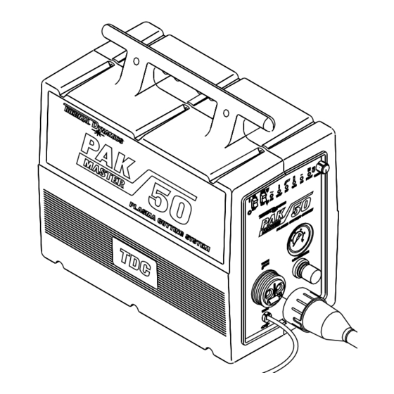
The PCH/M-35 includes a spare parts kit which provides an assortment of replacement consumable torch parts. • See page 12 for a list of other system options and accessories. Pak Master 50 Power Supply P IL P IP... -
Page 14: Specifications
2.02 SPECIFICATIONS ON/OFF Switch Controls RUN/SET Switch Output Current Control Corner Slowdown Control Pressure Regulator Control LED Indicators: Panel Indicators AC Power, TEMP, PIP (Parts-In-Place), GAS, DC Power, PILOT Pressure Gauge Input Power 200 to 460 VAC (±10%), 50 or 60 Hz, Single or Three-Phase 575V Requires Additional Transformer (Catalog No. - Page 15 2.02 SPECIFICATIONS (continued) PCH-35 70 ° Hand Torch 2.95 in (75 mm) 1.06 in (27 mm) 9.59 in (244 mm) PCH-35 90 ° Hand Torch 3.09 in 1.06 in (78 mm) (27 mm) 8.95 in (227 mm) 6.21 in (158 mm) Min. 14.72 in (374 mm) Max.
-
Page 16: Options And Accessories
2.03 OPTIONS AND ACCESSORIES Pak Master 50 • Remote Control (RC) Wire Harness ...... Cat. No. 9-6210 System Options and For converting a hand cutting system to mechanized use with a remote hand pendant control or computer control (CNC) cable. -
Page 17: Section 3: Installation
(1) Fuse - 2 Amp, 600V ..........Cat. No. 9-3861 (1) Spare Parts Container (without Parts) ....Cat. No. 8-3213 (1) Pak Master 50 Instruction Manual ..... Cat. No. 0-2470 Included with each machine torch system is: (1) Remote Control Hand Pendant ......Cat. No. 7-3114 (1) Remote Control Interface Wire Harness ... -
Page 18: Choosing A Location
3.02 CHOOSING A LOCATION Select a clean, dry location with good ventilation and adequate Choosing a Location working space around all components. The power supply is cooled by air flow through the rear panel. Air flow must not be obstructed. Provide at least 2 feet (0.61 m) of clearance in the rear. -
Page 19: Setting Up The Torch
3.03 SETTING UP THE TORCH Disconnect primary power at the source before disassembling WARNING the power supply, torch, or torch leads. Hand Torch Set-Up The torch parts (shield cup, tip, electrode, and gas distributor) must correspond with the type of operation (drag cutting, stand- off cutting, or gouging). - Page 20 3.03 SETTING UP THE TORCH (continued) Disconnect primary power at the source before disassembling WARNING the power supply, torch, or torch leads. Machine Torch Set-Up The torch parts (shield cup, tip, electrode, and gas distributor) must correspond with the type of operation (drag cutting, stand- off cutting, or gouging).
-
Page 21: Installing The Torch
3.04 INSTALLING THE TORCH Disconnect primary power at the source before disassembling WARNING the power supply, torch, or torch leads. This system is designed for use with the PCH/M-35 torch only. CAUTION Do not connect any other torch to this power supply. Installing the Torch 1. -
Page 22: Remote Control Harness Installation
3.05 REMOTE CONTROL HARNESS INSTALLATION RC Wire Harness Installation of the remote control (RC) wire harness is required for machine torch systems. Installation requires four #6-32 screws with locknuts. Disconnect primary power at the source before assembling or WARNING disassembling the power supply, torch parts, or torch and leads assemblies. - Page 23 3.05 REMOTE CONTROL HARNESS INSTALLATION (continued) Install the Wire Harness 3. Inside the power supply, locate the white 6-pin connector J7 on the top panel, close to the “REMOTE CONTROL” hole location. 4. Connect the 6-pin plug on the remote control wire harness to the 6-pin connector J7.
-
Page 24: Electrical Connections
3.06 ELECTRICAL CONNECTIONS Primary Input Voltages The unit can accept any input voltage from 200V to 460V (± 10%), single or three phase, 50 or 60 Hz. 575V input requires an addi- tional step-down transformer (Catalog No. 9-6211). CAUTION Input voltage settings must be verified before applying power to the unit. - Page 25 3.06 ELECTRICAL CONNECTIONS (continued) Both input voltage settings on the power supply must correspond CAUTION to the actual primary input voltage. Input Power Cable Systems ordered for 230V operation come supplied with a 230V Connections single-phase input power cable attached. For any other input voltage, the 230V input power cable must be removed and replaced with an appropriate power cable.
- Page 26 3.06 ELECTRICAL CONNECTIONS (continued) Ground Wire Input Power Cable A-00756 Input Power Cable Connections ø ø Single-Phase (1 Three-Phase (3 Figure 3-F Input Power Cable Connections Input Power Input Current Freq. Recommended Sizes Voltage 1-Ph 3-Ph 1-Ph 3-Ph Fuse (Amps) Wire (AWG) Wire (Canada)
-
Page 27: Work Cable And Ground Connections
3.07 WORK CABLE AND GROUND CONNECTIONS Electromagnetic High frequency pilot arc initiation generates electromagnetic Interference (EMI) interference (EMI), commonly called RF noise. EMI may interfere with nearby electronic equipment such as CNC controllers, etc. Torch leads are shielded to help prevent this problem. To further minimize RF interference, follow these grounding procedures when installing mechanized systems: Creating an Earth... -
Page 28: Gas Connections
3.08 GAS CONNECTIONS Gases Compressed Air or Nitrogen (N ) Only Pressure 70 psi (4.8 BAR) Flow Cutting - 200 scfh (94.4 lpm) Gouging - 230 scfh (108.5 lpm) CAUTION Max input pressure must not exceed 125 psi (8.6 BAR/860kPa) CAUTION Air supply must be free of oil, moisture, and other contaminants. - Page 29 3.08 GAS CONNECTIONS (continued) 7. Set the high pressure regulator to 100 psi and adjust the unit regulator for the desired 70 psi. CAUTION Always open the high pressure cylinder valve slowly to prevent damage to the unit gas regulator. Using Shop Air An air line filter (ordered separately) is required when using air from a compressor to insure that moisture and debris from the...
- Page 30 3.08 GAS CONNECTIONS (continued) Installing Refer to Figure 3-I and:. Air Line Filter 1. Press fit the nylon screw receptacles into the rear panel openings as shown. 2. Secure the air filter with bracket to the power supply with the 1/2 in pan head screws.
-
Page 31: Section 4: Operation
SECTION 4: OPERATION 4.01 OPERATING CONTROLS PIP (Parts-In-Place) Indicator GAS Indicator TEMP Indicator DC Indicator AC Indicator PILOT Indicator RUN/SET Switch CSD Control ON/OFF Switch Current Control TEMP PILOT CURRENT TORCH TORCH Receptacle Gas Pressure Gauge GAS PRESSURE WORK Cable Gas Pressure Control WORK Figure 4-A Operating Controls (See Table 4-A, page 28) - Page 32 4.01 OPERATING CONTROLS (continued) INDICATOR FUNCTION 1. ON/OFF Switch ON position supplies AC power to activate all system control circuits. OFF position deactivates control circuits. 2. RUN/SET Switch RUN position is used for torch operation. SET position is used for setting gas pressure and purging lines.
-
Page 33: Getting Started
4.02 GETTING STARTED Disconnect primary power at the source before disassembling WARNING the power supply, torch, or torch leads. Follow this set-up procedure each time the system is operated: Check Torch Parts 1. Check the torch for proper assembly and appropriate front end torch parts (see Torch Parts Selection, page 31 and Replacing Consumable Torch Parts, page 44). -
Page 34: Sequence Of Operation
4.03 SEQUENCE OF OPERATION ACTION ACTION ACTION ACTION Close external ON/OFF switch RUN/SET switch RUN/SET switch disconnect switch. to ON. to RUN. to SET. RESULT RESULT RESULT RESULT Power to system. AC, TEMP, PIP Gas flow stops. Gas solenoid open, indicators on. -
Page 35: Torch Parts Selection
4.04 TORCH PARTS SELECTION Torch Parts Selection The torch parts (shield cup, tip, electrode, and gas distributor) must correspond with the type of operation (drag cutting, stand- off cutting, or gouging). Standard Shield Cup (For Standoff Cutting) ......9-6003 Crown Shield Cup Standoff (For Drag Cutting) ....9-6004 Tip - Standoff Cutting ..............9-6000 Tip - Drag Cutting ..............9-6001 Tip - Drag Cutting (Heavy Duty) .......... -
Page 36: Cut Quality
4.05 CUT QUALITY Cut quality requirements differ depending on application. For instance, nitride build-up and bevel angle may be major factors when the surface will be welded after cutting. Dross-free cutting is important when finish cut quality is desired to avoid a second- ary cleaning operation. - Page 37 4.05 CUT QUALITY (continued) TYPE OF MATERIAL MATERIAL THICKNESS Carbon Steel Stainless Steel Aluminum Good - Excellent Good - Excellent Good - Excellent Gage to 1/2 in. Nitrogen Good Good Good Table 4-B Cut Quality on Various Materials and Material Thicknesses Description of Cut Excellent - Minimum bevel (0 - 4°), minimum kerf (2 x tip orifice Characteristics...
-
Page 38: Operating The System
4.06 OPERATING THE SYSTEM Disconnect primary power at the source before disassembling WARNING the power supply, torch, or torch leads. Frequently review the Important Safety Precautions at the front of this Manual. Be sure the operator is equipped with proper WARNING gloves, clothing, eye and ear protection. - Page 39 4.06 OPERATING THE SYSTEM (continued) Dross High speed dross usually forms a narrow bead along the bottom (continued) of the cut edge and is very difficult to remove. When cutting a troublesome steel, it is sometimes useful to reduce the cutting speed to produce slow speed dross.
-
Page 40: Operating With A Hand Torch
4.07 OPERATING WITH A HAND TORCH Cutting with a 1. The torch can be comfortably held in one hand or steadied Hand Torch with two hands. Choose the technique that feels most com- fortable and allows good control and movement. Position the index finger or thumb to press the control switch on the torch handle. -
Page 41: Operating With A Machine Torch
4.08 OPERATING WITH A MACHINE TORCH Disconnect primary power at the source before disassembling WARNING the power supply, torch, or torch leads. NOTE Frequently review the Important Safety Precautions beginning on page iii of this manual. Using Corner Slowdown The corner slowdown (CSD) function provides a reduction in for Mechanized Cutting output current which corresponds with the reduced travel speed of a mechanized torch as it changes direction at a sharp corner. - Page 42 4.08 OPERATING WITH A MACHINE TORCH (continued) The machine torch can be activated by remote control pendant or Cutting with a Machine Torch by a remote interface device such as CNC. Refer to Figure 4-E below and: 1. Use a square to align the torch perpendicular to the work- piece to obtain a clean, vertical cut (see Setting Up the Torch, page 20).
- Page 43 4.08 OPERATING WITH A MACHINE TORCH (continued) Proper tip-to-work (standoff) distance is critical to ensure accu- Standoff Distance racy, optimum cut quality, and maximum consumable parts life in mechanical systems. The recommended standoff distance for mechanized systems is 3/16 in (5 mm). Travel Speed Proper travel speed is indicated by the trail of the arc which is seen below the plate (see Figure 4-E, page 38).
-
Page 44: Recommended Cutting Speeds
4.09 RECOMMENDED CUTTING SPEEDS Cutting speed depends on material, thickness, and the operator’s Recommended ability to accurately follow the desired cut line. The following Cutting Speeds factors may have an impact on system performance: • Torch parts wear • Air quality •... -
Page 45: Gouging
4.10 GOUGING Be sure the operator is equipped with proper gloves, clothing, eye and ear protection and that all safety precautions at the front of this manual have been followed. Make sure no part of the WARNING operator’s body comes in contact with the workpiece when the torch is activated. - Page 46 4.10 GOUGING (continued) Standoff Distance The tip to work distance affects gouge quality and depth. A standoff of 1/8 - 1/4 in (3 - 6 mm) allows smooth, consistent metal removal. A smaller standoff may result in a severance cut rather than a gouge.
-
Page 47: Section 5: Customer/Operator Service
SECTION 5: CUSTOMER/OPERATOR SERVICE 5.01 GENERAL POWER SUPPLY MAINTENANCE Routine Maintenance The only routine maintenance required for the power supply is a thorough cleaning and inspection, with the frequency depending on the usage and the operating environment. Disconnect primary power to the system before disassembling WARNING the torch, leads, or power supply. -
Page 48: Replacing Consumable Torch Parts
5.02 REPLACING CONSUMABLE TORCH PARTS Disconnect primary power to the system before disassembling WARNING the torch, leads, or power supply. DO NOT TOUCH internal torch parts while the AC indicator on WARNING the front panel of the power supply is lit. The tip, gas distributor, and electrode are held in place by the NOTE shield cup. -
Page 49: General Torch Maintenance
5.02 REPLACING CONSUMABLE TORCH PARTS (continued) 4. Remove the electrode. The face of the electrode should not be recessed more than 0.10 inch (2.5 mm). If it is worn beyond this point it must be replaced. 5. Reinstall the parts and shield cup on the torch as shown. Hand tighten the shield cup until it is seated on the torch head. - Page 50 5.03 GENERAL TORCH MAINTENANCE (continued) Checking the The center insulator separates the negative and positive charged Center Insulator sections of the torch. If the center insulator does not provide adequate resistance, current which is intended for the pilot arc may be dissipated into the torch head, resulting in torch failure. Disconnect primary power to the system before disassembling WARNING the torch, leads, or power supply.
-
Page 51: Servicing Torch Head Components
5.04 SERVICING TORCH HEAD COMPONENTS Disconnect primary power to the system before disassembling WARNING the torch, leads, or power supply. NEVER touch any internal torch parts while the AC indicator WARNING light on the front panel of the control module is lit. Tools Required (1) No. - Page 52 5.04 SERVICING TORCH HEAD COMPONENTS (continued) Disconnect primary power to the system before disassembling WARNING the torch, leads, or power supply. Tools Required (1) No. 1 Phillips Head Screwdriver (1) No. 1 Slotted Head Screwdriver (2) 1/4 inch Open End Wrench (1) Pin Removal Tool (Catalog No.
- Page 53 5.04 SERVICING TORCH HEAD COMPONENTS (continued) Disconnect primary power to the system before disassembling WARNING the torch, leads, or power supply. Removing a Hand Refer to Figure 5-D and: Torch Head 1. Slide the torch handle back over the leads to expose the negative/plasma lead connection, the pilot lead connection, and the two PIP (parts-in-place circuit) connectors.
- Page 54 5.04 SERVICING TORCH HEAD COMPONENTS (continued) Handle O-Rings Torch Head Mounting Screws PIP Pin Assemblies A-00157 Figure 5-E Disassembling the Split Holder Disconnect primary power to the system before disassembling WARNING the torch, leads, or power supply. Replacing the Refer to Figure 5-F (page 51) and: PIP Assembly 1.
- Page 55 5.04 SERVICING TORCH HEAD COMPONENTS (continued) Replacing the 5. Position both PIP leads through the notch where the nega- PIP Assembly tive/plasma lead exits the holder. (continued) 6. Position the torch head inside the holder. Align the notch on the pilot lead with the corresponding tab on the split holder. Make sure the negative/plasma fitting is securely inserted in the groove in the holder.
- Page 56 5.04 SERVICING TORCH HEAD COMPONENTS (continued) Disconnect primary power to the system before disassembling WARNING the torch, leads, or power supply. Reassembling the Refer to Figure 5-D (page 49) and: Hand Torch Handle and 1. Connect the two PIP lead connectors and the negative/ Switch Assembly plasma and pilot leads.
-
Page 57: Servicing Torch Leads Components
5.05 SERVICING TORCH LEADS COMPONENTS Disconnect primary power to the system before disassembling WARNING the torch, leads, or power supply. (1) 3/32 inch Allen Wrench Tools Required (1) 15/16 inch (or Adjustable) Open End Wrench (1) 11/16 inch (or Adjustable) Open End Wrench (1) No. - Page 58 5.05 SERVICING TORCH LEADS COMPONENTS (continued) NOTE - PCH/M-35 Quick Disconnect Replacement Kit (Catalog No. 9-5836) includes all quick disconnect items. Outer Retaining Rotate outer retaining ring to access all three set screws Set Screw (Three) Signal Pin Connector Gently press tabs inward and remove connector Quick Disconnect Body (Torch End)
- Page 59 5.05 SERVICING TORCH LEADS COMPONENTS (continued) 10 11 12 13 14 A-00018 Pins Description Torch Switch 3, 4 Parts-In-Place (PIP) 1, 6 Shield (GND) 13, 14 Pilot Return - Positive Negative - Gas Figure 5-H Torch Quick Disconnect Fitting - Front End View Manual 0-2470 CUSTOMER/OPERATOR SERVICE...
-
Page 60: Torch And Leads Troubleshooting
5.06 TORCH AND LEADS TROUBLESHOOTING Disconnect primary power to the system before disassembling WARNING the torch, leads, or power supply. DO NOT touch any internal torch parts while the AC indicator WARNING light on the front panel of the power supply is lit. Checking the 1. - Page 61 5.06 TORCH AND LEADS TROUBLESHOOTING (continued) Checking the 6. If the torch quick disconnect assembly is okay, check the Torch Leads torch leads by measuring the resistance between the positive pilot lead connector and the negative/plasma lead fitting. If continuity is found, replace the torch leads. If no continuity is found, the torch leads are okay.
-
Page 62: Power Supply Troubleshooting
5.07 POWER SUPPLY TROUBLESHOOTING Troubleshooting and repairing the Pak Master 50 power supply is a process which should be undertaken only by those familiar with high voltage high power electronic equipment. There are extremely dangerous voltage and power levels present inside this unit. - Page 63 5.07 POWER SUPPLY TROUBLESHOOTING (continued) SYMPTOM POSSIBLE CAUSE REMEDY A. AC indicator not lit. 1. Input power not properly 1. Check that input power is connected to input panel present and properly connected (see Electrical Connections, page 20) 2. Input power selection does 2.
- Page 64 5.07 POWER SUPPLY TROUBLESHOOTING (continued) SYMPTOM POSSIBLE CAUSE REMEDY C. (continued) 5. Faulty LDD board* 5. Check and replace if necessary. See Service Procedures (page 66) D. AC indicator lit, TEMP 1. Gas not connected or 1. Check source for at least indicator green, PIP pressure too low 70 psi (4.8 BAR).
- Page 65 5.07 POWER SUPPLY TROUBLESHOOTING (continued) SYMPTOM POSSIBLE CAUSE REMEDY G. DC indicator not lit when 1. Switch activated during 20 1. Release switch and wait at torch switch is activated second pre-flow least 20 seconds before activating switch again 2. DC output not present* 2.
-
Page 66: Service Procedures
5.08 SERVICE PROCEDURES This section explains how to remove and replace any of the replaceable subassemblies listed in the Troubleshooting Guide. Disconnect primary power to the system before disassembling WARNING the torch, leads, or power supply. Opening the Enclosure There are eight mounting screws with nuts which secure the enclosure. - Page 67 5.08 SERVICE PROCEDURES (continued) Pilot Inductor (L4) The only reason the pilot inductor should be replaced is if the cores are cracked due to shipping damage or the unit being dropped. Minor chips are normal. If any burning or arcing is visible on the pilot inductor, return the unit to an authorized service center.
- Page 68 5.08 SERVICE PROCEDURES (continued) Work Lead Inductor (L7) The work lead inductor has a core of steel laminations and should never need replacing. If any burning or arcing is visible on the work lead inductor, return the unit to an authorized service center.
- Page 69 5.08 SERVICE PROCEDURES (continued) High Frequency To replace the high frequency transformer: Transformer (T2) 1. Disconnect the two high voltage leads from the spark gap assembly. 2. Unplug the J18 connector. 3. Remove the four mounting screws. 4. Install the replacement HF transformer on the bottom chassis. Plug in the J18 connector and replace the high voltage leads to the spark gap assembly.
- Page 70 5.08 SERVICE PROCEDURES (continued) Checking the To check the Log/Gate Drive/Display (LDD) PC board assembly, LDD Board measure for 15-18 VAC from J1-9 to J1-7 and from J1-9 to J1-6. If 15-18 VAC is not present, replace the LDD board. Replacing the Since the LDD board contains no high power circuitry, but does LDD Board...
- Page 71 5.08 SERVICE PROCEDURES (continued) Fan Assembly The fan assembly consists of a rotary fan, an attached spacer plate, and a foam seal. To replace the fan assembly: 1. Remove the LDD board to expose the top panel. 2. Remove the two nuts which hold the input connection block from the top panel.
- Page 72 5.08 SERVICE PROCEDURES (continued) DC Output Check Disconnect the primary coil (J18 ) of the HF transformer and check for approximately 300VDC on the output connector to the torch (positive and negative). If 300VDC is present, check torch and leads for open. If not, then send unit to an authorized service station.
-
Page 73: Section 6: Parts List
SECTION 6: PARTS LIST 6.01 ORDERING INFORMATION Parts listed without item numbers are not shown, but may be ordered by the catalog number shown. Order replacement parts by catalog number and complete de- scription of the part or assembly, as listed in the description column of the Parts List. -
Page 74: System Components And Accessories
Machine torch systems include metal mounting tube and pinion assembly and remote pendant control with ON/OFF switch: 1-6249 Pak Master 50 with PCH-35 70° Torch and 12.5 ft (3.8 m) Leads 1-6250 Pak Master 50 with PCH-35 70° Torch and 25 ft (7.6 m) Leads 1-6251 Pak Master 50 with PCH-35 70°... -
Page 75: Front Panel Components
6.03 FRONT PANEL COMPONENTS Item Qty. Catalog Description Reference Number Designator 9-6236 Front Panel 9-6207 Regulator/Solenoid Assembly (see page 62) 9-5834 Quick Disconnect Replacement Kit - Includes Items 3-6: Quick Disconnect Body Quick Disconnect Retaining Ring Clip Quick Disconnect Body Wave Spring Washer 9-4488 Socket Retaining Ring Clip 9-6237... -
Page 76: Regulator/Solenoid Assembly
6.04 REGULATOR/SOLENOID ASSEMBLY Item Qty. Catalog Description Reference Number Designator 9-6207 Regulator/Solenoid Assembly - Includes: 8-4382 Regulator 8-3370 Solenoid Valve, 1/8 NPT 8-5533 Pressure Switch, 42 psi 8-0354 Fitting - 1/8 NPT Close Nipple 8-3369 Reducer Bushing 9-6220 Gauge - 0-100 PSI/BAR 9-6230 Fitting - 1/4 NPT x 3/8 Tube, Straight 9-2023... -
Page 77: Base Panel Components
6.05 BASE PANEL COMPONENTS Item Qty. Catalog Description Reference Number Designator 8-2192 Auxiliary Transformer - IEC Models 9-6202 Work Lead Inductor 9-6203 Output Inductor Assembly 9-5528 High Frequency Transformer Assembly 9-6205 Spark Gap Assembly 9-6229 Single Circuit Receptacle 9-6200 Main Transformer 9-6201 Pilot Inductor Assembly 9-6213... -
Page 78: Chassis Components
Access Panel - Input Voltage Connection 9-6251 Access Panel - Voltage Changeover 9-6252 Vinyl Cap - Torch Quick Disconnect 9-6253 Voltage Tag 9-6254 Upper Side Panel Overlay “Pak Master 50” 9-6255 Lower Side Panel Overlay “TDC” 9-6256 Input Power Connection Label 8-3216 USA Label 8-5544... - Page 79 A-00775 Manual 0-2470 PARTS LIST...
-
Page 80: Rear Panel Components
6.07 REAR PANEL COMPONENTS Item Qty. Catalog Description Number 9-6228 Rear Panel 9-6209 Fan Assembly 9-6229 Single Circuit Receptacle 9-6230 Fitting - 1/4 NPT x 3/8 Tube 8-4289 Flex Connector 8-4251 Finger Guard 9-6231 Nine Circuit Receptacle 9-3861 Fuse - 2 amp, 600V Retaining Ring (.300 inch I.D.) 9-5562 Fuse Holder (IEC Internal Style Only) -
Page 81: Replacement Torches And Leads
6.08 REPLACEMENT TORCHES AND LEADS Qty. Catalog Description Number Replacement Hand Torches with Leads and Spare Parts Kit: 2-6001 PCH-35 70° Hand Torch, 12.5 ft (3.8 m) Leads, Spare Parts Kit 2-6002 PCH-35 70° Hand Torch, 25 ft (7.6 m) Leads, Spare Parts Kit 2-6003 PCH-35 70°... -
Page 82: Torch Heads And Split Holders
5.9 TORCH HEADS AND SPLIT HOLDERS Item Qty. Catalog Description Number 9-5807 Basic Internal Head - PCH-35 70° Hand Torch 9-5808 Basic Internal Head - PCH-35 90° Hand Torch 9-5809 Basic Internal Head - PCM-35 Machine Torch 9-6259 Split Holder (Two Parts) - PCH-35 70° Hand Torch 9-5856 Split Holder (Two Parts) with PIP Parts - PCH-35 70°... -
Page 83: Consumable Torch Parts
5.10 CONSUMABLE TORCH PARTS Qty. Catalog Description Number 9-6003 Standard Shield Cup (For Standoff Cutting) 9-6004 Shield Cup Standoff Attachment (for Drag Cutting) 9-6000 Tip - Standoff Cutting 9-6001 Tip - Drag Cutting 9-6120 Tip - Drag Cutting (Heavy Duty) 9-6002 Tip - Gouging 9-6006... -
Page 84: Torch Options And Accessories
6.11 TORCH OPTIONS AND ACCESSORIES Item Qty. Catalog Description Number 7-3247 PCH-35 Cutting Guide Kit 4-6007 Leads Extension Kit - PCH-35 Hand Torch - 25 ft (7.6 m) 4-6008 Leads Extension Kit - PCH-35 Hand Torch - 50 ft (15.2 m) 4-6009 Leads Extension Kit - PCM-35 Machine Torch - 25 ft (7.6 m) 4-6010... - Page 85 Manual 0-2470 PARTS LIST...
-
Page 86: Torch Spare Parts Kits
6.12 TORCH SPARE PARTS KITS Qty. Catalog Description Number 5-6028 Spare Parts Kit - PCH/M-35 MaximimLife™ - Includes: 9-6503 MaximimLife™ Shield Cup Attachment (Install Over Standard Cup) 9-6500 MaximimLife™ Standoff Cutting Tip 9-6501 MaximimLife™ Drag Cutting Tip 9-6506 MaximimLife™ Electrode 9-6507 MaximimLife™... - Page 87 This Page Left Blank Manual 0-2470 APPENDIX...
-
Page 88: Appendix I: System Schematic
APPENDIX I: SYSTEM SCHEMATIC A-00804 APPENDIX Manual 0-2470... - Page 89 A-00804 Manual 0-2470 APPENDIX...
- Page 90 APPENDIX Manual 0-2470...
Need help?
Do you have a question about the Pak Master 50 and is the answer not in the manual?
Questions and answers