
Related Manuals for Thermal Dynamics Pak Master 75XL Plus


Summary of Contents for Thermal Dynamics Pak Master 75XL Plus
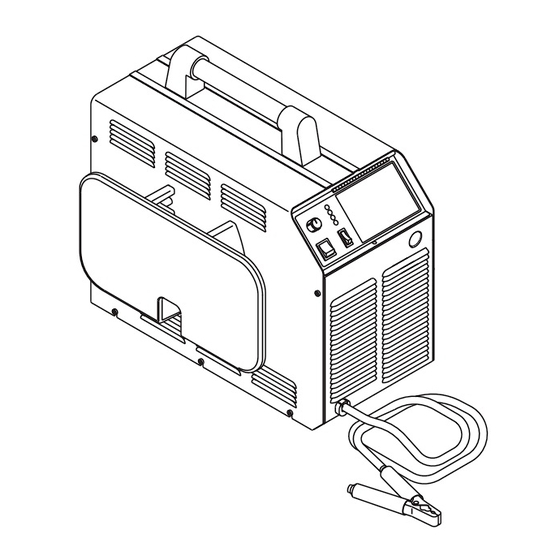
- Page 1 PLASMA CUTTING POWER SUPPLY ® Pak Master 75XL™ Plus A-02464 Service Manual September 15, 2003 Manual No. 0-2747...
- Page 3 Manufacturer assumes no liability for its use. Plasma Cutting Power Supply Pak Master ® 75XL Plus Service Manual Number 0-2747 Published by: Thermal Dynamics Corporation 82 Benning Street West Lebanon, New Hampshire, USA 03784 (603) 298-5711 www.thermal-dynamics.com Copyright 1999 by Thermal Dynamics Corporation All rights reserved.
-
Page 4: Table Of Contents
TABLE OF CONTENTS SECTION 1: GENERAL INFORMATION ....................1-1 1.01 Notes, Cautions and Warnings ..............1-1 1.02 Important Safety Precautions ............... 1-1 1.03 Publications ....................1-2 1.04 Note, Attention et Avertissement ..............1-3 1.05 Precautions De Securite Importantes ............1-3 1.06 Documents De Reference ................ - Page 5 TABLE OF CONTENTS (continued) SECTION 6: REPLACEMENT PARTS ....................6-1 6.01 Introduction ....................6-1 6.02 Ordering Information ................... 6-1 6.03 Major External Replacement Parts .............. 6-2 6.04 Access Panel Replacement Parts ............... 6-3 6.05 Front Panel Replacement Parts ..............6-4 6.06 Left Side Internal Component Replacement Parts ........
-
Page 7: General Information
SECTION 1: GASES AND FUMES GENERAL INFORMATION Gases and fumes produced during the plasma cutting process can be dangerous and hazardous to your health. 1.01 Notes, Cautions and Warnings • Keep all fumes and gases from the breathing area. Throughout this manual, notes, cautions, and warnings Keep your head out of the welding fume plume. -
Page 8: Publications
• Wear dry gloves and clothing. Insulate yourself from the work piece or other parts of the welding PLASMA ARC RAYS circuit. • Repair or replace all worn or damaged parts. Plasma Arc Rays can injure your eyes and burn your skin. •... -
Page 9: Note, Attention Et Avertissement
6. ANSI Standard Z49.2, FIRE PREVENTION IN THE USE ATTENTION OF CUTTING AND WELDING PROCESSES, obtain- able from American National Standards Institute, 1430 Broadway, New York, NY 10018 Toute procédure pouvant résulter l’endommagement du matériel en cas de non- 7. AWS Standard A6.0, WELDING AND CUTTING CON- respect de la procédure en question. - Page 10 • Eloignez toute fumée et gaz de votre zone de respira- • Ne touchez jamais une pièce “sous tension” ou “vive”; tion. Gardez votre tête hors de la plume de fumée portez des gants et des vêtements secs. Isolez-vous provenant du chalumeau. de la pièce de travail ou des autres parties du circuit de soudage.
-
Page 11: Documents De Reference
ultra-violets très forts. Ces rayons d’arc nuiront à vos 1.06 Documents De Reference yeux et brûleront votre peau si vous ne vous protégez pas correctement. Consultez les normes suivantes ou les révisions les plus récentes ayant été faites à celles-ci pour de plus amples •... - Page 12 9. Norme 70 de la NFPA, CODE ELECTRIQUE NA- TIONAL, disponible auprès de la National Fire Pro- tection Association, Batterymarch Park, Quincy, MA 02269 10. Norme 51B de la NFPA, LES PROCÉDÉS DE COUPE ET DE SOUDAGE, disponible auprès de la National Fire Protection Association, Batterymarch Park, Quincy, MA 02269 11.
-
Page 13: Declaration Of Conformity
Rigorous testing is incorporated into the manufacturing process to ensure the manufactured product meets or exceeds all design specifications. Thermal Dynamics has been manufacturing products for more than 30 years, and will continue to achieve excellence in our area of manufacture. -
Page 14: Statement Of Warranty
None Warranty repairs or replacement claims under this limited warranty must be submitted by an authorized Thermal Dynamics® repair facility within thirty (30) days of the repair. No transportation costs of any kind will be paid under this warranty. Transportation charges to send products to an authorized warranty repair facility shall be the responsibility of the customer. -
Page 15: Introduction
C. Customer/Operator Responsibilities It is the customer/operator's responsibility to maintain the equipment and peripheral Accessories provided by Thermal Dynamics in good operating order in accordance with the procedures outlined in the Operating Manual, and to protect the equipment from accidental or mali- cious damage. - Page 16 INTRODUCTION Manual 0-2747...
-
Page 17: Description
SECTION 3: 3.03 Specifications/Design Features DESCRIPTION A. Power Supply Technical Specifications The following specifications apply to the Power Supply only: 3.01 Scope 1. Front Panel Controls The purpose of the information in this section is: ON/OFF Switch, RUN/SET/LATCH Switch and •... -
Page 18: Power Supply Options And Accessories
9. Weight D. Multi-Purpose Cart 64 lbs (29 kg) w/work lead Rugged steel cart on easy-rolling rear wheels and front-mounted swivel casters. Provides maximum 71 lbs (32 kg) w/work lead and 25' Torch & Lead mobility for the power supply and can also serve as a display cart. -
Page 19: Troubleshooting
Handle torch leads with care and protect them from Section 4: damage. TROUBLESHOOTING A. Piloting Piloting is harder on parts life than actual cutting be- 4.01 Introduction cause the pilot arc is directed from the electrode to the tip rather than to a workpiece. Whenever possible, This section provides service diagnostics for the Pak avoid excessive pilot arc time to improve parts life. -
Page 20: Troubleshooting Guide - General Information
Manual requires Power Supply disassembly and live mea- surements. It is helpful for solving many of the common b. Torch standoff too high from workpiece problems that can arise with the Pak Master 75XL PLUS Power Supply. c. Worn torch parts If major complex subassemblies are faulty, the faulty sub- d. -
Page 21: Circuit Fault Isolation
C. How to use the Troubleshooting Guide A. Initial Setup Conditions The following information is a guide to help the Service 1. Connect gas supply to rear of Power Supply. Technician determine the most likely causes for various 2. Turn on gas supply and adjust Power Supply Gas symptoms. -
Page 22: Main Input And Internal Power Problems
2. Single phase jumper wire installed incorrectly C. Pilot Arc Test a. Refer to Operating Manual 0-2746, Section 3.07 1. Activate the torch (press torch switch on the and check jumper wire installation. handle, START signal from CNC or press the torch switch on the Remote Pendant) and note the fol- 3. - Page 23 10. Faulty ON/OFF switch (refer to Appendix 10, 36 V AC 4. Faulty RUN/SET/LATCH switch Circuit Diagram) a. Check continuity. Measure for 36 VAC on the Logic/Gate PC Board 5. Faulty gas solenoid circuit between J3-2 to J3-4. a. Test gas solenoid circuit per Section 4.09-G; re- a.
- Page 24 5. Faulty Wiring or Logic/Gate PC Board Check for DC voltage from Logic/Gate PC Board Pilot Output PC Board J2-13 to TP1 (GND) • If less than a volt, replace Logic/Gate PC Board TP1 (GND) A-01399 Pin 3 Pin 1 A-02546 Logic/Gate PC Board G.
-
Page 25: Pilot Arc Problems
C. No arc in torch; Gas flows; AC indicator ON; 4.07 Pilot Arc Problems TEMP indicator off; GAS and DC indicators ON; No arc at spark gap on CD PC Board; CD enable Locate your symptom below: indicator (D2) ON A. -
Page 26: Main Arc Problems
5. Faulty torch 4.08 Main Arc Problems a. Check continuity per appropriate Torch Instruc- Locate your symptom below: tion Manual. A. Main cutting arc will not start. 6. Faulty connection of wire #16 or #17 to Pilot Output PC Board 1. -
Page 27: Test Procedures
2. Faulty PCR Relay 1. Remove the screws which secure the left side panel (viewed from front of unit) to the frame assembly. a. With power off, measure for continuity between wires #12 and #14. If continuity is found, re- place PCR. - Page 28 D. Input PC Board Test Check Input PC Board for shorted input diode. A-00307 0.75 Solder Side of PC Board Forward Bias Diode Conducting Diode Test Symbol VR COM Anode Cathode Testing Diode Forward Bias 6. Reverse the meter leads across the diode for reverse Input PC Board bias testing (refer to following figure).
- Page 29 If Input Bridge Diode is shorted, make the following F. Temperature Circuit Test checks with an ohmmeter at the Main Contactor: Test the temperature circuit per the following: 1. Place the front panel ON/OFF switch to the OFF M e t e r (+ ) M e t e r (-) I n d ica t io n position.
- Page 30 12. Check for short on Connector (harness end) be- H. Pilot Arc Circuit tween J2-15 & 16. Check across E23 to E24 at the Pilot Output PC Board. If shorted, replace TS1. There should be a diode drop across E23 to E24 in one direction and an open in the other.
- Page 31 CD PC Board A-01202 Logic/Gate PC Board A-02550 1. No DC Output An open circuit voltage of approximately 280 to 325 vdc (depending on input power selected) is produced b. Connect a jumper between TP1 and TP8 of the when switching transistors in the FET/Heatsink As- Logic/Gate PC Board.
- Page 32 e. If voltage is okay, check torch & leads. If volt- 3. MOSFET Resistance Checks age is low, disconnect wire from E24 on Pilot The Power Supply contains two identical FET/Heat- Output Board and recheck steps c-d. If volt- sink Assemblies. On each assembly there are two age is still low, disconnect wires 11-12 (from MOSFET devices that must be checked.
- Page 33 Place the meter (+) lead on gate lead of Q6 and 5. FET Output Rectifier Check meter (-) lead on source lead of Q6. The meter Use a digital meter, diode or ohms function, to check should indicate approximately 2.5K ohms. the forward and reverse bias of the output rectifiers Place the meter (+) lead on drain lead of Q6 and on the FET/Heatsink Assemblies as follows:...
- Page 34 Place the meter (+) lead on E18 and the meter (-) lead on the heatsink of the FET/Heatsink Assem- bly to check the output rectifier resistance to ground. The meter should indicate >1 meg ohms. Replace the FET/Heatsink Assemblies if any of the above tests are open or shorted.
-
Page 35: Replacement Procedures
Connect the equipment primary cable ground to SECTION 5: the same electrical ground as the wrist strap. REPLACEMENT Open the equipment enclosure (see instruction manual for the appropriate equipment) and remove PROCEDURES the failed PC Board. Carefully open the ESD protective bag and remove 5.01 Introduction the replacement PC Board. -
Page 36: Major External Parts Replacement
C. Right Side Panel Replacement 5.04 Major External Parts Replacement Remove the Lifting Handle per paragraph 'A' above. Unlock the latch for the Access Panel. Refer to Section 6 for parts list and overall detailed draw- ing. Using a Phillips head screwdriver remove the two screws and loosen the three bottom screws which A. -
Page 37: Front Panel Parts Replacement
B. ON/OFF Switch Replacement Remove the two nuts and washers securing the Ac- cess Panel to the Right Side Panel. Unlatch the Access Panel to gain access to the rear Install the replacement Access Panel by reversing of the ON/OFF Switch. the above procedure. -
Page 38: Left Side Internal Component Parts Replacement
d. On the right side remove the two screws secur- C. Input PC Board Assembly Replacement ing the Pilot Panel to the Base/Front Panel As- Follow the Anti-Static Handling Procedures in Section 5.02. sembly. Remove the Left Side Panel per Section 5.04-B. e. - Page 39 Install the replacement Input Diode Bridge Assem- bly and new Thermal Pad by reversing the above Connection Description procedure (see Note). Main Transformer (Primary) NOTE Main Transformer (Primary) The two nuts removed in Step 3 must be torqued to Main Transformer (Secondary) 35 in-lbs when reinstalled.
-
Page 40: Rear Panel Parts Replacement
B. Optional Single Stage Air Line Filter 5.08 Rear Panel Parts Replacement Element Replacement Refer to Section 6 for parts list and detailed drawing, and This part is an option; it may not be installed on all units. replacement parts catalog numbers. NOTE A. - Page 41 C. Optional Two Stage Air Line Filter D. Pressure Switch Replacement Replacement Remove power from power supply. This part is an option: it may not be installed on all units. Shut off air supply and bleed down system. Remove power from power supply. 3.
-
Page 42: Right Side Internal Component Parts Replacement
Remove the four screws securing the Air Line Regu- Disconnect all the wiring connections to the Pilot/ lator Bracket to the Rear Panel. Output PC Board Assembly. Pull the bracket from the unit. Remove the four screws and washers securing the PC Board to the standoffs. - Page 43 D. Main Transformer Assembly Replacement F. Auxiliary Transformer Assembly Replacement Remove the Left Side Panel per Section 5.04-B. Remove the Left Side Panel per Section 5.04-B. Remove the Right Side Panel per Section 5.04-C. Remove the Right Side Panel per Section 5.04-C. Remove the following terminal connections from the two FET/Heatsink Assemblies noting the loca- Disconnect the white wire single pin connector...
- Page 44 G. Bulkhead Adapter Replacement Remove the Right Side Panel per Section 5.04-C. Remove Torch connection at the Bulkhead Adapter. A-02562 Tube Fitting Bracket Bulkhead Adapter Disconnect the gas tube from the fitting at the end of the Bulkhead Adapter. Remove the fitting. 5.
-
Page 45: Replacement Parts
SECTION 6: REPLACEMENT PARTS 6.01 Introduction A. Parts Breakdown The Parts Lists provide a breakdown of all replaceable components. The Parts Lists are arranged as follows: Section 6.03 Major External Replacement Parts Section 6.04 Access Panel Replacement Parts Section 6.05 Front Panel Replacement Parts Section 6.06 Left Side Internal Component Replace- ment Parts Section 6.07 Rear Panel Replacement Parts... -
Page 46: Major External Replacement Parts
6.03 Major External Replacement Parts Item # Description Catalog # Tube, Lifting Handle,1.125 OD,11.85 Lg 9-7505 Mount, Lifting Handle 9-7506 Cover, Left Side Includes: 9-8001 Cover Left Side Label, Warning, English Cover, Right Side Includes: 9-8016 Cover Right Side Overlay, RH Side Panel Labels Label, Warning, French Leads Wrap Includes:... -
Page 47: Access Panel Replacement Parts
6.04 Access Panel Replacement Parts Item # Description Catalog # Assembly, Pot/Led PCB 9-8004 Knob,Inner Concentric 9-8007 On/Off Rocker Switch, DPST 8-3258 Switch, Rocker, SPST 8-3259 Panel, Access Includes: For Units with PCH/M-60 Torch: 9-8018 Overlay, Access Panel Label, Access Panel For Units With PCH/M-102 Torch: 9-6693 Overlay, Access Panel... -
Page 48: Front Panel Replacement Parts
6.05 Front Panel Replacement Parts Item # Description Catalog # Panel, Base/Front Includes: 9-8019 Base/Front, Unit USA Label Ground Tag Overlay, Front Panel Contactor, Main, 4P, 40 FLA, 600V, 120VAC 9-7507 Strain Relief, .325-.60 8-5537 Work Cable, #6 AWG w/Clamp – 20 ft 9-8008 Clamp 9-8120... - Page 49 This page left blank. Manual 0-2747 REPLACEMENT PARTS...
-
Page 50: Left Side Internal Component Replacement Parts
6.06 Left Side Internal Component Replacement Parts Item # Description Catalog # Insulator, Input PCB See Note 1 Cable Ass’y, 10 Cir Ribbon, 15" Lg 9-5922 Gate / Logic PCB Assembly 9-8020 FET/ Heatsink Assembly Kit, includes: 9-8021 FET/ Heatsink Assembly Dust Cover, FET Ass’y Fuse Block 9-5562... - Page 51 A-02566 HARDWARE #10-32 Regular Nylon Lock Nut #10-32 x 2" PPH HDMS #10-32 x 0.5" PPH Sw ageform Stl Zn Screw 1/4-20 x 3" Screw , Soc HD #6-32 x 3 1/2" THD Screw #10-32 x 3/4" PPH Sw ag Screw #6-32x3/8 PPH STL ZN Screw NOTE: Illustration may vary Rubber Feet...
-
Page 52: Rear Panel Replacement Parts
6.07 Rear Panel Replacement Parts Item # Description Catalog # Pressure Switch-35 PSI 9-1044 Valve, Solenoid 1/8 NPT 8-3370 Regulator, Air Line 9-7514 Strain Relief 8-6307 1/4 NPT Street Elbow 9-2184 1/8 NPT Str. Tee 8-0352 1/4-1/8 NPT Reducer 9-2023 Fitting, 1/8 NPT X 2"... - Page 53 Part of #4 A-02535 NOTE: Illustration may vary slightly from actual unit Manual 0-2747 REPLACEMENT PARTS...
-
Page 54: Right Side Internal Component Replacement Parts
6.08 Right Side Internal Component Replacement Parts Item # Description Catalog # Bulkhead Adapter, O2B - 1/8 NPT 9-4045 9/16-18 Jam Nut, Brass 8-2149 Heatsink, Input Bridge (Shown With Pad) See Note 1 Chassis, Center See Note 1 Panel, Pilot Ass’y Mounting See Note 1 Brkt, Bulkhead Mounting See Note 1... - Page 55 A-02567 HARDWARE #10-32 Regular Nylon Lock Nut #10-32 x 2" PPH HDMS #10-32 x 0.5" PPH Sw ageform Stl Zn Screw 1/4-20 x 3" Screw , Soc HD #6-32 x 3 1/2" THD Screw #10-32 x 3/4" PPH Sw ag Screw #6-32x3/8 PPH STL ZN Screw Rubber Feet NOTE: Illustration may vary slightly...
-
Page 56: Options And Accessories
6.09 Options and Accessories Description Catalog # Multi-Purpose Cart 7-8888 575V Transformer 9-7500 Cutting Guide Kit 7-8910 Filter Kit – Includes Filter And Hose 7-7507 Replacement Filter Body 9-7740 Replacement Filter Element 9-7741 Replacement Filter Hose (Not Shown) 9-7742 Two Stage Air Line Filter Kit 7-7500 Bracket, Filter Mounting (Not shown) 9-7535... -
Page 57: Appendix 1: Input Wiring Requirements
APPENDIX 1: INPUT WIRING REQUIREMENTS Input P ower Input Current S uggested S izes (See Notes) V oltage Freq. 1-Ph 3-Ph 1-Ph 3-Ph Fuse (Amps) W ire (AW G) W ire (Canada) (V olts) (Hz) (kVA) (kVA) (Amps) (Amps) 1-Ph 3-Ph 1-Ph 3-Ph... -
Page 58: Appendix 2: Sequence Of Operation (Block Diagram
APPENDIX 2: SEQUENCE OF OPERATION (BLOCK DIAGRAM) LATCH ACTION ACTION ACTION ACTION ON/OFF switch Close external RUN/SET/LATCH RUN/SET/LATCH switch to ON. disconnect switch. switch to RUN. to SET. RESULT RESULT RESULT RESULT AC indicator blinks for 8 Power to system. Gas flow stops. -
Page 59: Appendix 3: Pot/Led Pc Board Layout
APPENDIX 3: POT/LED PC BOARD LAYOUT A-01206 Pot/LED PC Board Signals J14-1 +10 vdc from Logic/Gate/Gate PC Board (J3-7) J14-2 Current Control to Logic/Gate PC Board (J3-8) J14-3 Return for Current Control from Logic/Gate PC Board (J3-9) J14-4 18VDC Unregulated from Logic/Gate PC Board (J3-10) J14-5 Active Low Signal for AC OK Indicator to Logic/Gate PC Board (J3-11) J14-6... -
Page 60: Appendix 4: Logic/Gate Pc Board Layout
APPENDIX 4: LOGIC/GATE PC BOARD LAYOUT TP18 TP24 TP23 TP21 TP25 A-02528 Logic/Gate PC Board TP22 TP26 TP20 J3-5 Logic LowFrom RUN/SET/LATCH Switch Logic/Gate PC Board Signals on Front Panel (RUN) J3-6 PCB Common J1-1 36 VAC from Auxiliary Transformer J3-7 +10 vdc to Front Panel Current Control Pot J14-1 J1-2... - Page 61 J3-1 36 VAC to ON/OFF Switch J7-1 +12VDC J3-2 36 VAC from ON/OFF Switch to Logic/Gate PC Board J7-2 J3-3 36 VAC to ON/OFF Switch J7-3 J3-4 36 VAC from ON/OFF Switch to Logic/Gate PC Board J7-4 J3-5 Logic Low - From RUN/SET/LATCH Switch on Front Panel (RUN) J7-5 PRI Current Signal J3-6...
-
Page 62: Appendix 5: Pilot Output Pc Board Layout
APPENDIX 5: PILOT OUTPUT PC BOARD LAYOUT CGND A-01389 Pilot Output PC Board Signals J12-1 Torch Switch Filter in from J22-3 Torch Control J12-2 Not Used J12-3 Torch Switch Filter Return from J22-4 Torch Control J12-4 Not Used J12-5 Pilot Return Shield to J22-1 Torch Control J12-6 Torch Switch Shield to J22-2 Torch Control J12-7... - Page 63 CGND Chassis Gnd PS(-) (Stud) from Output Inductor L1 to CD Xfmr PS(-) C4 Rtn for Pilot Voltage Twisted with Pilot RTN to E23 PS(+) to E18 Upper Fet Module PS(+) to E18 Upper Fet Module From E22 to PCR Pin 2 From Pilot Choke to E20 C4 Rtn for Pilot Voltage Twisted with Pilot RTN from E8 Pilot RTN from Standoff on bulk head and Torch Cable...
-
Page 64: Appendix 6: Cd Pc Board Layout
APPENDIX 6: CD PC BOARD LAYOUT J11-1 J11-3 J11-4 J11-5 A-01208 CD PC Board Signals J11-1 36 VAC from Logic PC Board (J5-1) J11-2 Return from Logic PC Board (J5-2) J11-3 36 VAC from Logic PC Board (J5-3) J11-4 CD Enable Signal from Logic PC Board (J5-4) J11-5 Return for CD Enable Signal from Logic PC Board (J5-5) J11-6... -
Page 65: Appendix 7: Input Pc Board Layout
APPENDIX 7: INPUT PC BOARD LAYOUT 2-position connector Solder Side of PC Board Component Side of PC Board Input PC Board A-02551 CGND Input PC Board Signals J16-1 Gate Drive Relay Rtn from Logic Board J10-1 J16-2 Gate Drive Relay Pos from Logic Board J10-2 J16-3 Not used J16-4... -
Page 66: Appendix 8: Fet Pc Board Layout
APPENDIX 8: FET PC BOARD LAYOUT Component side of PC Board E12B E13C A-02630 Solder Side of PC Board APPENDIX A-10 Manual 0-2747... - Page 67 FET PC Board Signals (Upper and Lower Assemblies) J6-1 +12V from the Gate Drive Board upper J7-1 Lower J8-1 J6-2 +12V RTN from the Gate Drive Board upper J7-2 Lower J8-2 J6-3 Pwm Output from the Gate Drive Board upper J7-3 Lower J8-3 J6-4 Pwn Output RTN J6-2 from the Gate Drive Board upper J7-4 Lower J8-4 J6-5...
-
Page 68: Appendix 9: Capacitor Pc Board Layout
APPENDIX 9: CAPACITOR PC BOARD LAYOUT E13B E12B E12A A-02633 E13C E12C Capacitor PC Board Signals Positive Rail to FET Board E12A Positive Rail to FET Board E12B Positive Rail to FET Board E12C Positive Rail to FET Board Negative Rail to FET Board E13A Negative Rail to FET Board E13B... -
Page 69: Appendix 10: 36Vac Circuit Diagram
APPENDIX 10: 36VAC CIRCUIT DIAGRAM CD PC Board Logic/Gate 12 VDC Drive PC Circuit Board Auxiliary 36 VAC Transformer Outputs 115 VAC A-02527 ON/OFF Switch Manual 0-2747 A-13 APPENDIX... -
Page 70: Appendix 11: Maintenance Schedule
APPENDIX 11: MAINTENANCE SCHEDULE This schedule applies to all types of non-liquid cooled plasma cutting systems. Some systems will not have all the parts listed and those checks need not be performed. NOTE The actual frequency of maintenance may need to be adjusted according to the operating environment. Daily Operational Checks or Every Six Cutting Hours: Check torch consumable parts, replace if damaged or worn. - Page 71 Notes: Manual 0-2747 A-15 APPENDIX...
-
Page 72: Appendix 12: System Schematic
APPENDIX 12: SYSTEM SCHEMATIC A-02503 APPENDIX A-16 Manual 0-2747... - Page 73 A-02503 Manual 0-2747 A-17 APPENDIX...
Need help?
Do you have a question about the Pak Master 75XL Plus and is the answer not in the manual?
Questions and answers