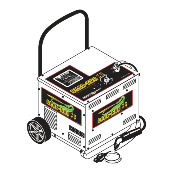
Thermal Dynamics Drag-Gun 38 Instruction Manual
Plasma cutting power supply used with pch-42 rpt surelok torch
Hide thumbs
Also See for Drag-Gun 38:
- Service manual (54 pages) ,
- Operating manual (54 pages) ,
- Operating manual (51 pages)
Table of Contents
Troubleshooting

Related Manuals for Thermal Dynamics Drag-Gun 38


Summary of Contents for Thermal Dynamics Drag-Gun 38
- Page 1 PLASMA CUTTING POWER SUPPLY Drag-Gun™ 38 Used With PCH-42 RPT SureLok™ Torch 4 RE 4 RE A-02145 Instruction Manual December 9, 2002 Manual No. 0-2879...
- Page 3 Published by: Thermal Dynamics Corporation 82 Benning Street West Lebanon, New Hampshire, USA 03784 (603) 298-5711 www.thermadyne.com Copyright 2001 by Thermal Dynamics Corporation All rights reserved. Reproduction of this work, in whole or in part, without written per- mission of the publisher is prohibited.
-
Page 4: Table Of Contents
TABLE OF CONTENTS SECTION 1: GENERAL INFORMATION ....................1-1 1.01 Notes, Cautions and Warnings ..............1-1 1.02 Important Safety Precautions ............... 1-1 1.03 Publications ....................1-2 1.04 Note, Attention et Avertissement ..............1-3 1.05 Precautions De Securite Importantes ............1-3 1.06 Documents De Reference ................ - Page 5 TABLE OF CONTENTS (continued) SECTION 6: PARTS LISTS ........................6-1 6.01 Introduction ....................6-1 6.02 Ordering Information ..................6-1 6.03 Power Supply Replacement Parts ..............6-2 6.04 Rear Panel Replacement Parts ..............6-4 6.05 Complete Assembly Replacement ............... 6-6 APPENDIX 1: SEQUENCE OF OPERATION BLOCK DIAGRAM ..........A-1 APPENDIX 2: ROUTINE MAINTENANCE SCHEDULE ............
-
Page 7: General Information
SECTION 1: GASES AND FUMES GENERAL INFORMATION Gases and fumes produced during the plasma cutting process can be dangerous and hazardous to your health. 1.01 Notes, Cautions and Warnings • Keep all fumes and gases from the breathing area. Throughout this manual, notes, cautions, and warnings Keep your head out of the welding fume plume. -
Page 8: Publications
• Wear dry gloves and clothing. Insulate yourself from the work piece or other parts of the welding PLASMA ARC RAYS circuit. • Repair or replace all worn or damaged parts. Plasma Arc Rays can injure your eyes and burn your skin. •... -
Page 9: Note, Attention Et Avertissement
6. ANSI Standard Z49.2, FIRE PREVENTION IN THE USE ATTENTION OF CUTTING AND WELDING PROCESSES, obtain- able from American National Standards Institute, 1430 Broadway, New York, NY 10018 Toute procédure pouvant résulter l’endommagement du matériel en cas de non- 7. AWS Standard A6.0, WELDING AND CUTTING CON- respect de la procédure en question. - Page 10 • Eloignez toute fumée et gaz de votre zone de respira- • Ne touchez jamais une pièce “sous tension” ou “vive”; tion. Gardez votre tête hors de la plume de fumée portez des gants et des vêtements secs. Isolez-vous provenant du chalumeau. de la pièce de travail ou des autres parties du circuit de soudage.
-
Page 11: Documents De Reference
ultra-violets très forts. Ces rayons d’arc nuiront à vos 1.06 Documents De Reference yeux et brûleront votre peau si vous ne vous protégez pas correctement. Consultez les normes suivantes ou les révisions les plus récentes ayant été faites à celles-ci pour de plus amples •... - Page 12 9. Norme 70 de la NFPA, CODE ELECTRIQUE NA- TIONAL, disponible auprès de la National Fire Pro- tection Association, Batterymarch Park, Quincy, MA 02269 10. Norme 51B de la NFPA, LES PROCÉDÉS DE COUPE ET DE SOUDAGE, disponible auprès de la National Fire Protection Association, Batterymarch Park, Quincy, MA 02269 11.
-
Page 13: Declaration Of Conformity
1.07 Declaration of Conformity Manufacturer: Thermal Dynamics Corporation Address: 82 Benning Street West Lebanon, New Hampshire 03784 The equipment described in this manual conforms to all applicable aspects and regulations of the ‘Low Voltage Directive’ (European Council Directive 73/23/EEC as amended by Council Directive 93/68/EEC) and to the National legislation for the enforcement of this Directive. -
Page 14: Statement Of Warranty
1.08 Statement of Warranty LIMITED WARRANTY: Thermal Dynamics ® Corporation (hereinafter “Thermal”) warrants that its products will be free of defects in workmanship or material. Should any failure to conform to this warranty appear within the time period applicable to the Thermal products as stated below, Thermal shall, upon notification thereof and substantiation that the product has been stored, installed, operated, and maintained in accordance with Thermal’s specifications, instructions, recommendations and recognized standard industry practice, and not subject to misuse, repair, neglect, alteration, or accident, correct such defects by suitable repair or replacement, at Thermal’s sole... -
Page 15: Introduction & Description
This manual contains descriptions, operating instructions The duty cycle will be reduced if the primary in- and maintenance procedures for the Drag-Gun 38 Plasma put voltage (AC) is low or the DC voltage is higher Cutting System. Service of this equipment is restricted than shown in the chart. - Page 16 12. Dimensions 38.5 inches (977.9 mm) 17 inches (39.37mm) 4 REV M AD M AD 4 REV A-02146 INTRODUCTION & DESCRIPTION Manual 0-2879...
-
Page 17: Installation Procedures
B. Removing Skid SECTION 3: The base of the power supply is secured to the skid with INSTALLATION lag screws. Remove the power supply from the skid per PROCEDURES the following procedure: 1. Remove the four lag screws securing the Power Supply to the skid. -
Page 18: Torch Connection
3.06 Torch Connection The Torch is installed to the Power Supply when ordered as part of the system. Use the following procedure only if the Power Supply and Torch were ordered separately: 1. Remove the Right Side Panel of the Power Sup- ply per Section 5.08-A-1. - Page 19 9. Connect the two torch control connectors and the pilot wire to the Main PC Board Assembly con- nections. Torch Control Connectors Pilot Wire Connection A-03239 Figure 3-4 Wiring Connections 10. Close the Power Supply by reinstalling the Right Side panel. Manual 0-2879 INSTALLATION PROCEDURES...
- Page 20 INSTALLATION PROCEDURES Manual 0-2879...
-
Page 21: Operation
6. CURRENT Control Guards SECTION 4: Guards used to protect the Current Control from OPERATION damage. 7. TORCH Lead 4.01 Introduction Access hole used to interface the Torch to the This section provides a description of the Plasma Cut- Power Supply. ting System followed by operating procedures. -
Page 22: Operating The System
C. Work Cable 2. Wear protective clothing then activate the torch. • Compressor pre-flow 1-1/2 to 2 seconds. Check for a solid work cable connection to the work- piece. • Pilot arc is established. 3. Move torch within transfer distance of work piece D. -
Page 23: Recommended Cutting Speeds
4.05 Recommended Cutting Speeds Cutting speed depends on the type of material, material thickness and operator ability to accurately follow the de- sired cut line. The following factors may have an impact on system performance: • Torch parts wear • Air quality •... - Page 24 OPERATION Manual 0-2879...
-
Page 25: Service
SECTION 5: CAUTIONS SERVICE Do not blow air into the power supply during clean- ing. Blowing air into the unit can cause metal par- ticles to interfere with sensitive electrical compo- 5.01 Introduction nents and cause damage to the unit. This section describes basic maintenance procedures that When cleaning, care must be taken not to move or can be performed by operating personnel, and advanced... -
Page 26: Troubleshooting Guides
d. Low air flow for plasma gas This guide is set up in the following manner: e. Improperly assembled torch X. Symptom (Bold Type) f. Output current too high Any Special Instructions (Text Type) g. Torch tip contacting workpiece 1. Cause (Italic Type) h. -
Page 27: Advanced Troubleshooting Guide
D. AC indicator ON, Over TEMP indicator dark, no 5.06 Advanced Troubleshooting gas flow when torch switch pressed. Guide 1. Shield cup not properly installed on torch. A. General a. Check that shield cup is fully seated against torch head. The troubleshooting covered in this Instruction Manual requires Power Supply disassembly and live measure- 2. - Page 28 Chart #1: Main Power AC Indicator OFF on Front Panel System Connect AC Power AC POWER Power Cable Operates Input Cable to Switch ON? Plugged In? Properly? AC Source Faulty AC Indicator Check Main Place AC POWER Replace Power Supply Power Disconnect Switch to ON Main Power...
- Page 29 Chart #2: Input Power Checks NOTE Check Input Diode Bridge on This condition could also result if the input Heatsink/PC Board Assembly line voltage was low, using an extension Per Section 5.08-B cable or the user was using a high standoff while cutting.
- Page 30 Chart #3: Temperature Indicator Checks AC and Gas Indicators are ON Temperature Indicator Either ON or Blinks Once When Torch is Activated Temp Indicator ON Steady Proceed to Chart #4 When Torch is (blinks once) Activated Duty Cycle Allow Power Supply Operating? Exceeded? To Cool...
- Page 31 Chart #4: Shorted Torch or Resistor (R3) Checks AC and Gas Indicators are ON DC Indicator Blinks or Momentary ON When Torch is Activated Check Pilot Wire per Section 5.08-E Pilot Wire Replace Check Correct? Leads Assembly Check Resistor (R3) Assembly per Section 5.08-F Resistor R3 Replace Resistor (R3)
- Page 32 Chart #5: Faulty Torch or Torch Switch Checks AC Indicator ON AC and Gas Indicators are ON No GAS Flow When Torch DC Indicator OFF is Activated When Torch is Activated Compressor Check Troubleshooting operates 4 seconds at per Section 5.05-C power ON? Check Torch And Leads Assembly...
- Page 33 Chart #6: Faulty Current Control CURRENT Control Knob Turns Completely Around And Doesn't Stop At Minimum Or Maximum Positions Check Shaft Of CURRENT Control Is Not Loose Or Broken From PC Board Is Control Replace Power Supply Shaft Okay? Secure or Replace CURRENT Control Knob per Section 5.09-C Manual 0-2879...
-
Page 34: Test Procedures
5.08 Test Procedures Torch Control The checks in these test procedures are all made with the Connectors main power disconnected. WARNINGS Disconnect primary power to the system at the source before opening the Power Supply. A. Opening Power Supply Enclosure 1. - Page 35 B. Checking Input Diode Bridge Testing of diode modules requires a digital volt/ohm meter that has a diode test scale or an analog VOM with 1X or X10 scale. Remember that even if the diode mod- ule checks good, it may still be bad. If in doubt, replace the Power Supply.
- Page 36 10. If the diode has visible damage or is shorted, the D. Checking Capacitor PC Board diode is faulty. Replace the Power Supply. 1. Remove the Top Panel of the Power Supply per paragraph A-2 above. A-00306 A-03252 Capacitor PC Board Reverse Bias Diode Not Conducting...
- Page 37 E. Checking Pilot Wire 1. Remove the Right Side Panel of the Power Sup- A-03254 ply per paragraph A-1 above. 2. Remove the Pilot Wire from the stud terminal on the Main PC Board. A-03253 Resistor (R3) Figure 5-10 Resistor R3 Location Pilot Wire 3.
- Page 38 Test for 208 or 230VAC between wires #19 and H. Checking Torch Switch #23 on TB1. 1. Remove the Right Side Panel of the Power Sup- • If the voltage is present and the Compres- ply per paragraph A-1 above. sor is humming, check the Starting Capaci- 2.
-
Page 39: Power Supply Component Replacement Procedures
C. Current Control Knob Replacement 5.09 Power Supply Component Replacement Procedures 1. Using a small blade screwdriver, loosen the screw securing the knob to the CURRENT Control ad- Refer to Section 6 for replacement parts lists, parts orien- justment shaft. tation and ordering information. - Page 40 E. Top Panel Replacement 8. Remove the Top Panel from the Power Supply a short distance (see note) being careful not to dam- 1. Remove the Current Knob per paragraph 'C' age the current control shaft. above. NOTE 2. Remove the Right Side Panel (see NOTE) per Sec- There is a ground wire attached to the inside of the tion 5.08-A-1.
- Page 41 5. Install the replacement Switch by reversing the H. Relay (K3) Replacement above steps. Depending on the unit, connect the 1. Remove the Left Side Panel per Section 5.08-A-1. wires to the Switch per one of the following Fig- ures: 2.
- Page 42 Input Power Cable Replacement 6. Pull the Input Power Cable from the unit. 7. Install replacement Power Cable by reversing the Depending on the unit, remove the Input Power Cable above steps. Connect the wires as shown in the per one of the following procedures: following Figure: •...
- Page 43 K. Current Control Knob Guard(s) Replacement NOTE Mounting Standoffs The torch lead and work lead must be disconnected to replace the Current Control Knob Guards. Capacitor PC Board 1. Remove the Top Panel per Section 5.08-A-2. 2. Remove the nuts securing Current Control Knob Guard(s) to the Top Panel.
- Page 44 O. Resistor (R3) Replacement 1. Remove the Right Side Panel per Section 5.08-A-1. 2. Remove the two screws securing the Center Di- vider to the Power Supply Base. 3. Lift the vertical Center Divider up and out to- wards the Compressor to gain access to the Re- sistor.
-
Page 45: Torch And Leads Replacement Procedure
6. Remove the Starting Capacitor from the Power 4. Disconnect the two Torch Control Connectors and Supply. the Pilot Wire from the Main PC Board Assembly connectors. 7. Install the replacement Starting Capacitor by re- versing the above steps. Reconnect the wires as follows: Torch Control Connectors... - Page 46 6. Loosen the torch lead fitting from the brass torch block. This fitting must be removed from the Torch Lead and installed on the replacement lead. CAUTION Be sure all wires are outside the protective insulat- ing sheet as noted above when it is reinstalled. High voltage is present on the torch negative lead.
-
Page 47: Parts Lists
SECTION 6: PARTS LISTS 6.01 Introduction A. Parts List Breakdown The parts list provides a breakdown of all replaceable components. Power Supply and Torch Assembly are field serviceable, so a complete breakdown of parts is provided. The parts lists are arranged as follows: Section 6.03 Power Supply Replacement Parts Section 6.04 Rear Panel Replacement Parts Section 6.05 Complete Assembly Replacements... -
Page 48: Power Supply Replacement Parts
6.03 Power Supply Replacement Parts Item # Description Catalog # Left Side Panel with Labels 9-7707 Right Side Panel with Labels 9-7708 Top Panel with Labels 9-7709 Rear Panel with Labels - Refer to Section 6.04 for Replacement Parts Front Panel with Labels 9-7706 Current Control Knob Assy 9-7710... - Page 49 A-03230 Manual 0-2879 PARTS LISTS...
-
Page 50: Rear Panel Replacement Parts
6.04 Rear Panel Replacement Parts Item # Description Catalog # Rear Panel with Labels Domestic Units ------ CE and Australian Units 9-7705 Handle 9-7712 ON/OFF Switch 8-4248 Filter Dryer Replacement Kit 9-6599 Filter Dryer Element 9-7718 9-1033 EMC Filter (For CE and Australian Units Only) 9-7950 The following parts are not shown: Input Power Cable... - Page 51 Domestic Units A-03264 CE & Australia Units A-03265 Manual 0-2879 PARTS LISTS...
-
Page 52: Complete Assembly Replacement
6.05 Complete Assembly Replacement Description Catalog # Domestic System includes: Power Supply with Built-In Air Compressor, Torch with Leads, Spare Parts Kit, Input Power Cable With Plug and Work Cable With Clamp. 70° Torch with 20 ft (6.1 m) Leads 1-3800 90°... -
Page 53: Appendix 1: Sequence Of Operation Block Diagram
APPENDIX 1: SEQUENCE OF OPERATION BLOCK DIAGRAM ACTION ACTION ON/OFF switch Plug in to ON. Power Cord RESULT RESULT AC Indicator flashes for Power to system. 3 seconds then stays on. Air Compressor runs for 3 seconds then off. Fan on. ACTION ACTION Torch moved away... -
Page 54: Appendix 2: Routine Maintenance Schedule
APPENDIX 2: ROUTINE MAINTENANCE SCHEDULE This schedule applies to all types of non-liquid cooled plasma cutting systems. Some systems will not have all the parts listed and those checks need not be performed. NOTE The actual frequency of maintenance may need to be adjusted according to the operating environment. Daily Operational Checks or Every Six Cutting Hours: 1. -
Page 55: Appendix 3: Recommended Cutting Speeds
APPENDIX 3: RECOMMENDED CUTTING SPEEDS NOTE Cutting speeds are for use with PCH-42 RPT Torch. Drag-Gun 38 Cutting Speeds (Air Pressure @ 50 psi for all settings) Recommended Recommended Maximum Cut Material Thickness Speed @29 Standoff Speed @ 29 Speed @ 20 Amps... -
Page 56: Appendix 4: Non-Ce System Schematic
APPENDIX 4: NON-CE SYSTEM SCHEMATIC A-02201 APPENDIX Manual 0-2879... - Page 57 NOTE Refer to Appendix 5 for CE & Australia Power Supplies. A-02201 Manual 0-2879 APPENDIX...
-
Page 58: Appendix 5: Ce & Australia System Schematic
APPENDIX 5: CE & AUSTRALIA SYSTEM SCHEMATIC A-02576 APPENDIX Manual 0-2879... - Page 59 NOTE Refer to Appendix 4 for all other Power Supplies. A-02576 Manual 0-2879 APPENDIX...
Need help?
Do you have a question about the Drag-Gun 38 and is the answer not in the manual?
Questions and answers