Table of Contents
Advertisement
Advertisement
Table of Contents

Related Manuals for Thermal Dynamics PAK MASTER 75XL PLUS


Summary of Contents for Thermal Dynamics PAK MASTER 75XL PLUS
- Page 1 A-02464 Manual No. 0-2746 August 23, 1999...
- Page 2 While the information contained in this Operating Manual WARNING represents our best judgement, Thermal Dynamics Corporation assumes no liability for its use. ® Pak Master 75XL Plus Air Plasma Cutting Power Supply...
- Page 3 Record Serial Numbers For Warranty Purposes Purchase Date Power Supply Torch...
-
Page 5: Table Of Contents
TABLE OF CONTENTS SECTION 1: GENERAL INFORMATION ....................1 1.01 Notes, Cautions and Warnings ..............1 1.02 Important Safety Precautions ................ 1 1.03 Publications ....................2 1.04 Note, Attention et Avertissement ..............3 1.05 Precautions De Securite Importantes ............3 1.06 Documents De Reference ................ - Page 6 TABLE OF CONTENTS (continued) SECTION 6: PARTS LISTS ........................31 6.01 Introduction ....................31 6.02 Ordering Information ..................31 6.03 Complete Power Supply Replacement ............32 6.04 Replacement Parts ..................32 6.05 Options and Accessories ................32 APPENDIX I: INPUT WIRING REQUIREMENTS ..............33 APPENDIX II: SEQUENCE OF OPERATION (BLOCK DIAGRAM) ...........
-
Page 7: Section
SECTION 1: GASES AND FUMES GENERAL INFORMATION Gases and fumes produced during the plasma cutting process can be dangerous and hazardous to your health. 1.01 Notes, Cautions and Warnings • Keep all fumes and gases from the breathing area. Throughout this manual, notes, cautions, and warnings Keep your head out of the welding fume plume. -
Page 8: Publications
• Install and maintain equipment according to NEC • To protect your eyes, always wear a welding hel- code, refer to item 9 in Subsection 1.03, Publica- met or shield. Also always wear safety glasses with tions. side shields, goggles or other protective eye wear. •... -
Page 9: Note, Attention Et Avertissement
8. NFPA Standard 51, OXYGEN-FUEL GAS SYSTEMS FOR WELDING, CUTTING AND ALLIED PRO- AVERTISSEMENT CESSES, obtainable from the National Fire Protection Association, Batterymarch Park, Quincy, MA 02269 9. NFPA Standard 70, NATIONAL ELECTRICAL CODE, Toute procédure pouvant provoquer des blessures obtainable from the National Fire Protection Asso- de l’opérateur ou des autres personnes se trouvant ciation, Batterymarch Park, Quincy, MA 02269... - Page 10 • Les sortes de gaz et de fumée provenant de l’arc de plasma dépendent du genre de métal utilisé, des INCENDIE ET EXPLOSION revêtements se trouvant sur le métal et des différents procédés. Vous devez prendre soin lorsque vous Les incendies et les explosions peuvent résulter des scories coupez ou soudez tout métal pouvant contenir un chaudes, des étincelles ou de l’arc de plasma.
-
Page 11: Documents De Reference
• Utilisez la nuance de lentille qui est suggèrée dans 4. Norme ANSI Z87.1, PRATIQUES SURES POUR LA le recommendation qui suivent ANSI/ASC Z49.1: PROTECTION DES YEUX ET DU VISAGE AU TRAVAIL ET DANS LES ECOLES, disponible de Nuance Minimum Nuance Suggerée Courant Arc Protective Numéro... - Page 12 14. Norme AWSF4.1 de l’Association Américaine de Soudage, RECOMMANDATIONS DE PRA- TIQUES SURES POUR LA PRÉPARATION À LA COUPE ET AU SOUDAGE DE CONTENEURS ET TUYAUX AYANT RENFERMÉ DES PRODUITS DANGEREUX , disponible auprès de la American Welding Society, 550 N.W. LeJeune Rd., Miami, FL 33126 15.
-
Page 13: Declaration Of Conformity
Rigorous testing is incorporated into the manufacturing process to ensure the manufactured product meets or exceeds all design specifications. Thermal Dynamics has been manufacturing products for more than 30 years, and will continue to achieve excellence in our area of manufacture. -
Page 14: Statement Of Warranty
None Warranty repairs or replacement claims under this limited warranty must be submitted by an authorized Thermal Dynamics® repair facility within thirty (30) days of the repair. No transportation costs of any kind will be paid under this warranty. Transportation charges to send products to an authorized warranty repair facility shall be the responsibility of the customer. -
Page 15: Introduction
® 2.03 Specifications/Design Features 75XL Plus Air Plasma Cutting Power Supply. Service of this equipment is restricted to Thermal Dynamics trained A. Power Supply Technical Specifications personnel; unqualified personnel are strictly cautioned against attempting repairs or adjustments not covered in The following specifications apply to the Power Supply this manual, at the risk of voiding the Warranty. -
Page 16: Power Supply Options And Accessories
10. Overall Dimensions D. Smart Cart 19" (482 mm) High x 13" (330 mm) Wide x 24.8" (630 Steel cart on easy rolling 10" pneumatic tires to pro- mm)Long vide maximum mobility for the power supply. Handle is 3/4" tubing with hooks for storage of torch leads. Overall dimensions are with Handle, Lead Wrap A tie down strap is also included. -
Page 17: Installation Procedures
least 6 inches (0.2 m) on each side for clearance . Provide SECTION 3: sufficient clearance in front of the unit to allow access to the front panel controls (minimum 6 inches or 0.2 m). INSTALLATION PROCEDURES CAUTION Operation without proper air flow will inhibit 3.01 Introduction proper cooling and reduce duty cycle. -
Page 18: Input Power Connections
• If using a fork lift vehicle, place and secure unit on a proper skid before transporting. • This unit has a handle mounted on top of the enclo- sure for hand lifting only. Be sure unit is lifted and Left Side transported safely and securely. -
Page 19: Primary Input Power Cable Connections
2. Connect the input cable inside the Power Supply for the type of operation per the following: Voltage Selection Label Three-Phase Operation 460 Volts Three-phase operation requires a 3-conductor cable 380/415 Volts with ground. 208/230/240 Volts a. Locate the ground stud and remove the top nut and washer. -
Page 20: Gas Connections
Single-Phase Operation Single-phase operation requires a 2-conductor cable Input Contactor with ground. a. Locate the single-phase jumper wire connected between the two L3 terminal lugs on the input contactor. b. Move one end of the jumper wire from termi- nal lug L3 to L2 at the contactor. NOTE The jumper wire from L1 to L4 must not be re- A-00915... - Page 21 B. Checking Air Quality D. Optional Air Line Filter Installation To test the quality of air, place the RUN/SET/LATCH Filtering is required when using air from a compressor to switch to SET position, place a welding filter lens in front insure that moisture and debris from the supply hose does of the torch and turn on the gas.
-
Page 22: Connecting Torch Leads
E. Using High Pressure Gas Cylinders 1. Refer to the following when using high pressure gas cylinders as the gas supply: Access Panel CAUTION Pressure should be set at 100 psi (6.9 bar) at the high pressure gas cylinder regulator. Screw a. -
Page 23: Work Cable And Ground Connections
4. Feed the end of the torch leads through the hole in the B. Creating an Earth Ground front panel in the following order: 1. Install a ground wire (not included) between the sys- • Control Cable tem and a solid earth ground (also called star ground). To create a solid earth ground, drive a 1/2 in (12 mm) •... -
Page 24: Tip Saver/Drag Cut Sensing Circuit
3.11 Tip Saver/Drag Cut Sensing Circuit This power supply is equipped with a Tip Saver/Drag Cut Sensing Circuit which cuts current back to 35 amps if the tip touches the workpiece. The purpose of this is to prolong the life of the tip. If the user does not want the current to be decreasedwhen the tip touches the workpiece, the sensing circuit can be defeated by closing switch SW1-1 on the Gate/Logic PC... -
Page 25: Operation
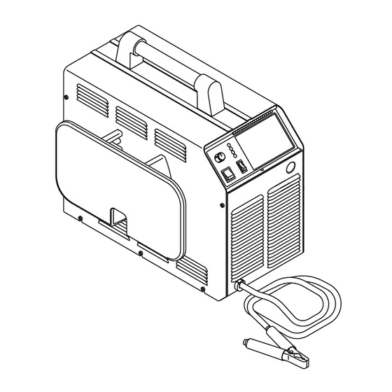
3. Torch Leads Input SECTION 4: Hole in the front panel to feed the torch leads through OPERATION to the internal bulkhead connections. 4. Work Cable and Clamp 4.01 Introduction Work cable with clamp (factory installed). This Section provides a description of the Power Supply 5. - Page 26 4. AC Power Indicator 3. Gas/Power Lead Connection Green LED indicator will blink ON then OFF for ap- Connects the torch gas/negative lead to the unit. proximately eight seconds and then stay ON after the D. Rear Panel ON/OFF power switch is set to ON. Indicates oper- ating power is present in the unit.
-
Page 27: Sequence Of Operation
3. Gas Pressure Regulator/Filter Assembly Pressure regulator to adjust the input gas pressure to the Power Supply. An air line filter is supplied as part of the pressure regulator. 4. Optional Filters a. Dry Air Filter Assembly This optional in-line filter removes moisture and con- taminants from the air stream when using compressed air. -
Page 28: Preparations For Operating
NOTE If torch is within 3/8 in (9.5mm) transfer distance of workpiece, main arc will transfer. GAS indicator will not come ON if the gas pres- sure is set below 35 psi (2.4 bar) at the Regulator/ 13. Gas will flow for 15 seconds (post-flow). Filter Assembly. - Page 29 Make a solid work cable connection to the work- piece or cutting table Copper Shield Cup Catalog No. 8-7496 Standard Shield Cup Crown Shield Cup Catalog No. 8-7500 Catalog No. 8-7507 Standoff Cutting Tip A-00925 Electrode Air/N2, 60 Amp Catalog No. 8-7502 Catalog No.
-
Page 30: Cut Quality
4.06 Cut Quality Kerf Width Cut quality requirements differ depending on applica- Cut Surface tion. For instance, nitride build-up and bevel angle may Bevel Angle be major factors when the surface will be welded after cutting. Dross-free cutting is important when finish cut Spatter quality is desired to avoid a secondary cleaning opera- tion. -
Page 31: Customer/Operator Service
Dynamics Trained personnel. Six Months or Every 720 Cutting Hours: For major troubleshooting and parts replacement pro- cedures refer to PAK Master 75XL Plus Power Supply 1. Check the in-line air filter(s), clean or replace as Service Manual 0-2747. required 5.02 General Maintenance... -
Page 32: Common Operating Problems
Make sure no part of the operator’s body comes into contact with the workpiece while the torch is acti- vated. Housing CAUTION Sparks from the cutting process can cause damage to coated, painted, and other surfaces such as glass, Filter Element plastic and metal. -
Page 33: Troubleshooting Guide
2. Main Arc Extinguishes For major troubleshooting and parts replacement pro- cedures refer to PAK Master 75XL PLUS Power Supply a. Cutting speed too slow Service Manual 0-2747. b. Torch standoff too high from workpiece C. - Page 34 1. Cause (Italic Type) a. Check and connect to proper input power line a. Check/Remedy (Text Type) 5. Faulty components in unit Locate your symptom, check the causes (easiest listed first) a. Return for repair or have qualified technician then remedies. Repair as needed being sure to verify that repair per Service Manual.
-
Page 35: Power Supply Parts Replacement
a. Check and adjusted to proper setting. 5.05 Power Supply Parts Replacement 3. Faulty components in unit a. Return for repair or have qualified technician repair per Service Manual. WARNING G. Erractic or improper cutting output 1. Poor input or output connections Disconnect primary power to the system before dis- assembling the torch, leads, or power supply. - Page 36 B. Fuse Replacement 1. Remove the left side panel per paragraph "A" above. 2. Locate the internal fuse above the input power con- tactor on the left side of the unit. 3. Replace the fuse (0.8 amp, 600V). 4. Reinstall the left side panel per paragraph "A" above.
-
Page 37: Parts Lists
Parts listed without item numbers are not shown, but may be ordered by the catalog number shown. B. Returns If a Thermal Dynamics product must be returned for ser- vice, contact your Thermal Dynamics distributor. Mate- rials returned to Thermal Dynamics without proper au- thorization will not be accepted. -
Page 38: Complete Power Supply Replacement
6.03 Complete Power Supply Replacement Power supply includes: Work cable and clamp, pressure regulator/air filter, and operating manual. Description Catalog # PAK MASTER 75XL PLUS Power Supply 208/230VAC, Single-Phase With 50 Amp Input Plug and Cable 3-7556-1 460VAC, Three-Phase Without Input Plug and Cable 3-7556-2 6.04 Replacement Parts... -
Page 39: Appendix I: Input Wiring Requirements
APPENDIX I: INPUT WIRING REQUIREMENTS Input P ower Input Current Input Recommended S izes (See Notes) V oltage Freq. 1-Ph 3-Ph 1-Ph 3-Ph Fuse (Amps) W ire (AW G) W ire (Canada) (V olts) (Hz) (kVA) (kVA) (Amps) (Amps) 1-Ph 3-Ph 1-Ph 3-Ph... -
Page 40: Appendix Ii: Sequence Of Operation (Block Diagram)
APPENDIX II: SEQUENCE OF OPERATION (BLOCK DIAGRAM) LATCH ACTION ACTION ACTION ACTION ON/OFF switch Close external RUN/SET/LATCH RUN/SET/LATCH switch to ON. disconnect switch. switch to RUN. to SET. RESULT RESULT RESULT RESULT AC indicator blinks for 8 Power to system. Gas flow stops. - Page 41 This Page Left Blank Manual 0-2746 APPENDIX...
-
Page 42: Appendix Iii: System Schematic
APPENDIX III: SYSTEM SCHEMATIC INRUSH INRUSH A-02503 APPENDIX Manual 0-2746... - Page 43 OK TO MOVE 8/11/99 A-02503 Manual 0-2746 APPENDIX...
- Page 44 APPENDIX Manual 0-2746...
Need help?
Do you have a question about the PAK MASTER 75XL PLUS and is the answer not in the manual?
Questions and answers