Thermal Dynamics CutMaster 50 Operating Manual
Plasma cutting power supply
Hide thumbs
Also See for CutMaster 50:
- Instruction manual (90 pages) ,
- Operating manual (48 pages) ,
- Service manual (88 pages)

Subscribe to Our Youtube Channel
Related Manuals for Thermal Dynamics CutMaster 50


Summary of Contents for Thermal Dynamics CutMaster 50
- Page 1 Plasma Cutting Power Supply CutMaster™ 50 A-02766 Operating Manual April 21, 2003 Manual No. 0-2805...
- Page 2 While the information contained in this Manual represents the Manufacturer's best judgement, the Manufacturer assumes no liability for its use. Plasma Cutting Power Supply CutMaster 50 Operating Manual Number 0-2805 Published by: Thermal Dynamics Corporation 82 Benning Street...
-
Page 3: Table Of Contents
TABLE OF CONTENTS SECTION 1: GENERAL INFORMATION ....................1-1 1.01 Notes, Cautions and Warnings ..............1-1 1.02 Important Safety Precautions ............... 1-1 1.03 Publications ....................1-2 1.07 Declaration of Conformity ................1-4 1.08 Statement of Warranty .................. 1-5 SECTION 2: INTRODUCTION ...................... - Page 4 TABLE OF CONTENTS (continued) SECTION 6: PARTS LISTS ........................6-1 6.01 Introduction ....................6-1 6.02 Ordering Information ..................6-1 6.03 Power Supply Replacement ................. 6-2 6.04 Replacement Parts ..................6-2 6.05 Options and Accessories ................6-2 APPENDIX 1: INPUT WIRING REQUIREMENTS ..............A-1 APPENDIX 2: SEQUENCE OF OPERATION (BLOCK DIAGRAM) ......................
-
Page 5: General Information
SECTION 1: GASES AND FUMES GENERAL INFORMATION Gases and fumes produced during the plasma cutting process can be dangerous and hazardous to your health. 1.01 Notes, Cautions and Warnings • Keep all fumes and gases from the breathing area. Throughout this manual, notes, cautions, and warnings Keep your head out of the welding fume plume. -
Page 6: Publications
• Wear dry gloves and clothing. Insulate yourself from the work piece or other parts of the welding PLASMA ARC RAYS circuit. • Repair or replace all worn or damaged parts. Plasma Arc Rays can injure your eyes and burn your skin. •... - Page 7 6. ANSI Standard Z49.2, FIRE PREVENTION IN THE USE OF CUTTING AND WELDING PROCESSES, obtain- able from American National Standards Institute, 1430 Broadway, New York, NY 10018 7. AWS Standard A6.0, WELDING AND CUTTING CON- TAINERS WHICH HAVE HELD COMBUSTIBLES, ob- tainable from American Welding Society, 550 N.W.
-
Page 8: Declaration Of Conformity
Rigorous testing is incorporated into the manufacturing process to ensure the manufactured product meets or exceeds all design specifications. Thermal Dynamics has been manufacturing products for more than 30 years, and will continue to achieve excellence in our area of manufacture. -
Page 9: Statement Of Warranty
None Warranty repairs or replacement claims under this limited warranty must be submitted by an authorized Thermal Dynamics® repair facility within thirty (30) days of the repair. No transportation costs of any kind will be paid under this warranty. Transportation charges to send products to an authorized warranty repair facility shall be the responsibility of the customer. - Page 10 GENERAL INFORMATION May 14, 2002...
-
Page 11: Introduction
1. Input Power (See Note) and basic maintenance procedures for the CutMaster 50 Plasma Cutting Power Supply only. Servicing of this The CutMaster 50 is available for the following in- equipment is restricted to properly trained personnel; un- put power: qualified personnel are strictly cautioned against attempt- •... -
Page 12: Power Supply Options And Accessories
5. Weight D. Wheel Kit 52 lbs (23.6 kg) A kit with easy - rolling wheels, for maximum port- ability for the power supply. Weight includes Power Supply with Input Cable (and plug, on 208 / 230V units), Work Lead, and Torch & E. -
Page 13: Installation
SECTION 3: CAUTION INSTALLATION Operation without proper air flow will inhibit proper cooling and reduce duty cycle. 3.01 Introduction 3.03 Unpacking This Section describes installation of the Power Supply The product is packaged and protected to prevent dam- and connecting the Torch. age during shipping. -
Page 14: Primary Input Power Connections
C. 460-Volt Single-Phase Operation 3.05 Primary Input Power Connections The 460-Volt Power Supply is equipped with a four-con- ductor input power cable for 460VAC, Three-Phase in- Check your power source for correct voltage before plug- put power. The Power Supply will accept 460VAC, ging in or connecting the unit. -
Page 15: Gas Connections
5. Strip back the insulation on the individual wires C. Connecting Gas Supply to Unit and connect as follows: The gas supply connects to the Regulator / Filter Assem- • Line 1 wire to main input contactor terminal bly located on the rear of the unit. The connection is the same for compressed air or high pressure gas cylinders. - Page 16 D. Installing Optional Air Filter Kits 2. Optional Two-Stage Air Filter Kit This optional two-stage air line filter is also for use Additional filtering is recommended when using air from on compressed air shop systems. Filter removes mois- a compressor to ensure that moisture and debris from the ture and contaminants to at least 5 microns.
-
Page 17: Torch Connections
E. Using High Pressure Gas Cylinders A. Hand Systems Refer to the following when using high pressure gas cyl- inders as the gas supply: WARNING CAUTION Disconnect primary power at the source before dis- assembling the torch or torch leads. Pressure should be set at 100 psi (6.9 bar) at the high pressure gas cylinder regulator. - Page 18 B. Machine Systems (Unshielded Leads) 1. Remove the Cover of the Power Supply to gain Note: Actual Bulkhead access to the Torch Bulkhead Panel. See Section configuration may differ from that shown. 5.05. Adapter 2. Remove the strain relief nut from the Strain Re- Negative/Plasma Connector Lead Connection...
- Page 19 5. Connect the Control (PIP) Circuit Connectors to the mating connectors on the Adapter supplied Adapter on the Power Supply (see Warning). Negative/Plasma Connector Lead Connection Power Supply Adapter WARNING Control Circuit Remote Connectors Pendant The Adapter supplied with the Power Supply has Open Adapter two additional Shield Connectors that are used for...
-
Page 20: Ground Connections For Mechanized Applications
Cable Connector Cable Connector recommendations for wire size, type, and connection point locations. For Thermal Dynamics components it is recom- Circuit Control mended to use a minimum of 10 AWG (European 6 ) wire or flat copper braid with cross section equal... - Page 21 7. The plasma control cable should be shielded with the 2. Increasing the ground rod length beyond 20 - 30 ft shield connected only at the cutting machine end. (6.1 – 9.1 m) does not generally increase the effective- Connecting the shield at both ends will allow ground ness of the ground rod.
- Page 22 INSTALLATION 3-10 Manual 0-2805...
-
Page 23: Operation
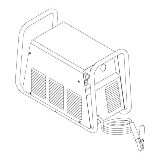
4. Roll Handle / Torch Leads Wrap SECTION 4: The torch leads and work cable wrap around the OPERATION handle for easy storage. 5. Torch Bulkhead Panel 4.01 Introduction The torch bulkhead panel is under the power sup- ply cover. See Section 5.05 for cover removal direc- This section identifies the front and rear components and tions. - Page 24 B. Control Panel Features GAS Indicator Green indicator will come ON when the input gas pressure is set to 35 psi (2.4 bar) or higher. Indicator will be OFF when the pressure falls below 35 psi (2.4 bar). DC Indicator Green indicator will come ON while the torch is acti- vated.
-
Page 25: Preparations For Operating
Prepare to Cut 4.03 Preparations For Operating Return the RUN / SET switch to RUN position. Gas This procedure should be followed at the beginning of will not flow until the Torch Trigger is pressed. each shift: The system is now ready for operation. Activate the torch (press torch switch on the handle, send START WARNING signal from CNC or press the torch switch on the Re-... - Page 26 9. Move Torch within transfer distance of workpiece. a. Main arc transfers. Pilot arc OFF. 10. Complete cutting operation. NOTE If the torch is lifted from the workpiece while the torch switch is activated, the main arc will stop and the pilot arc will automatically restart. 11.
-
Page 27: Service
5. The filter element and spool, with the baffle ring SECTION 5: in place (teeth facing downward) can be screwed SERVICE back into the Regulator body by compressing the spring on the spool. Tighten firmly by hand. 5.01 Introduction This section describes basic maintenance procedures per- formable by operating personnel. -
Page 28: Common Faults
Metal too thick d. Worn torch parts WARNING e. Cutting current too low f. Non-Genuine Thermal Dynamics parts used Always turn off the air supply and bleed the system before disassembling the Filter Assembly as injury could result. SERVICE... -
Page 29: Basic Troubleshooting Guide
Work cable disconnected each section in the order presented. e. Worn torch parts This guide is set up in the following manner: f. Non-Genuine Thermal Dynamics parts used X. Symptom (Bold Type) 3. Excessive Dross Formation Any Special Instructions (Text Type) a. - Page 30 3. Unit is overheated F. Limited output with no control a. Allow unit to cool down for at least 5 minutes. 1. Poor input or output connections Make sure the unit has not been operated be- a. Check all input and output connections. yond Duty Cycle limit.
-
Page 31: Power Supply Basic Parts Replacement
4. Faulty components in unit 2. Loosen, but do not remove, the lower screws, then carefully pull the Cover up and away a. Return for repair or have qualified technician from the unit for access to the inside of the repair per Service Manual. - Page 32 B. Fuse Replacement 1. Remove the unit cover per paragraph "A" above. 2. Locate the internal fuse on the left side of the cen- ter chassis. 3. Replace the fuse. Refer to Section 6.04 for proper fuse specification. 4. Reinstall the cover by reversing the steps in para- graph "A"...
-
Page 33: Parts Lists
SECTION 6: PARTS LISTS 6.01 Introduction A. Parts List Breakdown The parts list provide a breakdown of all replaceable com- ponents. The parts lists are arranged as follows: Section 6.03 Complete Power Supply Replacement Section 6.04 Replacement Parts Section 6.05 Options and Accessories NOTE Parts listed without item numbers are not shown, but may be ordered by the catalog number shown. -
Page 34: Power Supply Replacement
The following items are included with the replacement power supply: work cable & clamp, gas pressure regulator / filter, and operating manual. Description Catalog # CutMaster 50 Power Supply 208 / 230VAC, Single Phase, 60Hz, with input power cable and plug 3-5230 400VAC, Three Phase, 50 / 60Hz, with input power cable (only) -
Page 35: Appendix 1: Input Wiring Requirements
APPENDIX 1: INPUT WIRING REQUIREMENTS Input Power Input Current Input Suggested Sizes (See Notes) Fuse (Amps) Wire (AWG) Wire (Canada) Voltage Freq. 1-Ph 3-Ph 1-Ph 3-Ph (Volts) (Hz.) (kVA) (kVA) (Amps) (Amps) 1-Ph 3-Ph 1-Ph 3-Ph 1-Ph 3-Ph 17.5 17.5 Line Voltages with Suggested Circuit Protection and Wire Sizes Based on National Electric Code and Canadian Electric Code NOTES... -
Page 36: Appendix 2: Sequence Of Operation (Block Diagram
APPENDIX 2: SEQUENCE OF OPERATION (BLOCK DIAGRAM) ACTION ACTION ACTION ACTION ON/OFF switch Close external RUN/SET RUN/SET switch to ON. disconnect switch. switch to RUN. to SET. RESULT RESULT RESULT RESULT AC indicator blinks for 8 Power to system. Gas flow stops. Gas solenoid open, seconds then steady on. -
Page 37: Appendix 3: Torch Control Cable Wiring Diagram
APPENDIX 3: TORCH CONTROL CABLE WIRING DIAGRAM This diagram applies to mechanized systems only. Torch Control Cable Control Connector Plug with Connectors Torch Control Connectors Control Shield Connector Torch Lead Lead Shield A-02801 Assembly Connectors only on Connector Shielded Leads Mate &... -
Page 38: Appendix 4: Maintenance Schedule
APPENDIX 4: MAINTENANCE SCHEDULE This schedule applies to all types of non liquid cooled plasma cutting systems. Some systems will not have all the parts listed and those checks need not be performed. NOTE The actual frequency of maintenance may need to be adjusted according to the operating environment. Daily Operational Checks or Every Six Cutting Hours: 1. - Page 39 Notes: Manual 0-2805 APPENDIX...
-
Page 40: Appendix 5: System Schematic For 208 / 230V Units
APPENDIX 5: SYSTEM SCHEMATIC FOR 208 / 230V UNITS A-03269 APPENDIX Manual 0-2805... - Page 41 A-03269 Manual 0-2805 APPENDIX...
-
Page 42: Appendix 6: System Schematic For 400 / 460V Units
APPENDIX 6: SYSTEM SCHEMATIC FOR 400 / 460V UNITS A-02967 APPENDIX Manual 0-2805... - Page 43 A-02967 Manual 0-2805 APPENDIX...
- Page 44 APPENDIX A-10 Manual 0-2805...
Need help?
Do you have a question about the CutMaster 50 and is the answer not in the manual?
Questions and answers