Advertisement
Quick Links
Download this manual
See also:
Operating Manual
IC30 Series Service Manual
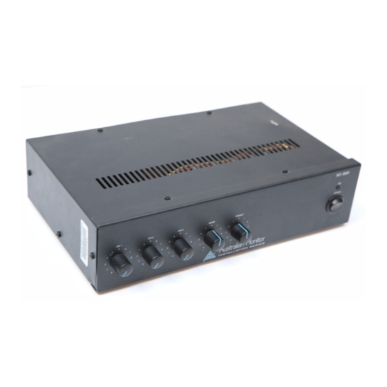
Product Description
Set-Up/Test Procedures
Component Lists
Full Schematics
PCB Overlays
Australian Monitor. Private Bag 149 Silverwater NSW 1811. Australia
Advertisement

Related Manuals for AUSTRALIAN MONITOR IC30 Series


Summary of Contents for AUSTRALIAN MONITOR IC30 Series
- Page 1 IC30 Series Service Manual Product Description Set-Up/Test Procedures Component Lists Full Schematics PCB Overlays Australian Monitor. Private Bag 149 Silverwater NSW 1811. Australia...
- Page 2 www.australianmonitor.com.au...
-
Page 3: Circuit Description
IC30 Circuit Description The IC30 is a 30 watt mixer amplifier which operates on 230/240 VAC, 50Hz or 12 VDC via an external DC power supply source. The amplifier is supplied free standing with rubber feet but can be rack mounted via an optional rack mount kit (IC30RMK). -
Page 4: Tape Output
Muting The last two(2) terminals on the barrier strip are for muting. Channels 2 and 3 are muted when the two mute contacts are shorted together. The muting is done by a FET switch so there is no ramping. An optional VOX muting module (TX3010) is also available with has ramping. - Page 5 Rack Mouting Kit An optional rack mounting kit (IC30RMK) is available to mount the IC30 in a standard 19" equipment rack. Fuse Sizes Mains 230 VAC: 1 Amperes Slow Blow The DC fuse is located on the circuit board. This is a feature of the AMIS series amplifiers, which are equipped with a current limiting circuit preventing excessive DC currents, thus eliminating the risk of blowing high tension fuses.
- Page 6 +14VDC +14VDC 330P AUX1 100R TAPE OUT 680R MIC1 100P LM1458 IC1A LM1458 +10V IC2B 680R 0.47 +10V 0.03 330P 100R TDA1516 470u 330P 100V AUX2 PIN 14 4066 IC3A 4066 680R 4 OHM MIC2 1200P LM1458 IC1B 680R +14VDC +10V 330P 330P...
- Page 9 IC30 Parts List Designator Part Type Description Manufacturer's Code Electrolytic capacitor 63V 2121280010 Electrolytic capacitor 63V 2121280010 330P Multi layer ceramic capacitor 100V 2127181331 330P Multi layer ceramic capacitor 100V 2127181331 Electrolytic capacitor 63V 2121280010 Electrolytic capacitor 63V 2121280010 Electrolytic capacitor 63V 2121280010 Electrolytic capacitor 63V 2121280010...
- Page 10 4.0A 4.0 Amp Anti-surge Fuse 2541210840 LM1458 IC Dual Op Amp DIP8 2152870558 LM1458 IC Dual Op Amp DIP8 2152870558 4066 I.C. CD 4066BCN VCA (14 PIN) 2159440066 TDA1516 Amplifier IC TDA1516BQ 2153121516 TDA1516 Amplifier IC TDA1516BQ 2153121516 LM741 LM741 IC 2152080741 Transistor BD139 2141400139...
- Page 11 Resistor, metalfilm .5W 9111590472 Potentiometer linear 2021000503 Resistor, metalfilm .5W 9111590473 Rocker switch SPST 2511213112...
- Page 12 WORK INSTRUCTION Testing of IC 30 1. Perform physical inspection ( Visual Inspection stage ) 1.1 Check : • All screws for tightness ( esp. H/S & IC fixing). • Capacitors for polarity. • Earth connection for good contact (XLR gnd to AC earth), including earthing of RCA’s, •...
- Page 13 5. Function Checks (Final stage). 5.1 Move signal generator to Mic2. Turn up volume control. Watch for irregularities. Check for 10.5V out. 5.2 Move signal generator to Mic3. Turn up volume control. Watch for irregularities. Check for 10.5V out. 6. Line level inputs (Final stage). 6.1 Connect signal generator to Line1 input.
- Page 14 WORK INSTRUCTION Testing of IC 30 1. Perform physical inspection ( Visual Inspection stage ) 1.1 Check : • All screws for tightness ( esp. H/S & IC fixing). • Capacitors for polarity. • Earth connection for good contact (XLR gnd to AC earth), including earthing of RCA’s, •...
- Page 15 5. Function Checks (Final stage). 5.1 Move signal generator to Mic2. Turn up volume control. Watch for irregularities. Check for 10.5V out. 5.2 Move signal generator to Mic3. Turn up volume control. Watch for irregularities. Check for 10.5V out. 6. Line level inputs (Final stage). 6.1 Connect signal generator to Line1 input.
Need help?
Do you have a question about the IC30 Series and is the answer not in the manual?
Questions and answers