
Related Manuals for RCF TX 2006


Summary of Contents for RCF TX 2006
- Page 1 OWNER MANUAL MANUALE D’USO TX 2006 UHF DIVERSITY WIRELESS MICROPHONES PX 2106 RADIOMICROFONI UHF “DIVERSITY”...
-
Page 3: Table Of Contents
INDEX INDICE ENGLISH SAFETY PRECAUTIONS DESCRIPTION RACK MOUNTING OF A PAIR OF RX 2006 RECEIVERS RX 2006 FRONT PANEL RX 2006 REAR PANEL TX 2000 TRANSMITTER / HANDHELD DYNAMIC MICROPHONE PX 2100 BODY PACK TRANSMITTER OPERATION SPECIFICATIONS ITALIANO AVVERTENZE PER LA SICUREZZA DESCRIZIONE INSTALLAZIONE A RACK (19”) DI UN PAIO DI RICEVITORI RX 2006 RX 2006 - PANNELLO FRONTALE RX 2006 – PANNELLO POSTERIORE TRASMETTITORE TX 2000 CON MICROFONO DINAMICO TRASMETTITORE PER CINTURA PX 2100 FUNZIONAMENTO DATI TECNICI... -
Page 4: Safety Precautions
(direct / alternating) corresponds to the product input voltage. If not, please contact your RCF dealer. Check also that the adapter has not been damaged due to possible clashes / hits or overloads. The mains voltage, which the adapter is connected to, is sufficiently high to involve a risk of electrocution: pay attention during the connection (i.e. never do it with wet hands) and never open the adapter. Make sure that the adapter cable is not (or cannot be) stepped on or crushed by other objects (pay particular attention to the cable part near the plug and the point where it leads out from the adapter). 3. Make sure that no objects or liquids can get into these products, as this may cause a short circuit. All devices shall not be exposed to dripping or splashing. No objects filled with liquid (such as vases) and no naked sources (such as lighted candles) shall be placed on receivers. 4. Never attempt to carry out any operations, modifications or repairs that are not expressly described in this manual. Contact your authorized service centre or qualified personnel should any of the following occur: The product does not function (or functions in an anomalous way) The adapter or its power supply cable has been damaged Objects or liquids have got into the unit The product has been subject to a heavy impact. 5. If this product is not used for a long period, unplug the receiver adapter and remove all batteries from the transmitter. 6. If a product begins emitting any strange odours or smoke, switch it off immediately, unplug the receiver adapter and/or remove batteries from the transmitter. 7. Do not connect this product to any equipment or accessories not foreseen. Check the suitability of the surface on which the receiver is placed, considering (for example) the mechanical vibrations normally generated by transducers. To prevent the risk of falling equipment, do not stack more receivers. 8. RCF S.p.A. strongly recommends this product is only installed by professional qualified installers (or specialised firms) who can ensure correct installation and certify it according to the regulations in force. The entire audio system must comply with the current standards and regulations regarding electrical systems. - Page 5 9. Supports and trolleys The equipment should be only used on trolleys or supports, where necessary, that are recommended by the manufacturer. The equipment / support / trolley assembly must be moved with extreme caution. Sudden stops, excessive pushing force and uneven floors may cause the assembly to overturn. 10. There are numerous mechanical and electrical factors to be considered when installing a professional audio system (in addition to those which are strictly acoustic, such as sound pressure, angles of coverage, frequency response, etc.). 11. Hearing loss Exposure to high sound levels can cause permanent hearing loss. The acoustic pressure level that leads to hearing loss is different from person to person and depends on the duration of exposure. To prevent potentially dangerous exposure to high levels of acoustic pressure, anyone who is exposed to these levels should use adequate protection devices.
-
Page 6: Description
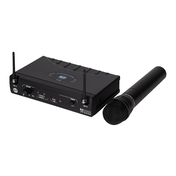
RCF S.P.A. THANKS YOU FOR PURCHASING THIS PRODUCT, WHICH HAS BEEN DESIGNED TO GUARANTEE RELIABILITY AND HIGH PERFORMANCE. DESCRIPTION TX 2006 and PX 2106 are UHF wireless microphones. Each receiver has 2 antennas for smart switching diversity control (the higher level radio signal is automatically selected), greater reliability and coverage, reduced risks of breakdowns and interferences. 16 different frequencies / channels are available. It is possible to use up to 6 channels simultaneously. Channels can be manually selected on all transmitters and receivers. TX 2006 kit consists of: a RX 2006 receiver (with AC / DC adapter and a 1.5 m cable with 1/4” jack plugs) a TX 2000 transmitter / handheld dynamic microphone Rack ears to mount a pair of RX 2006 receivers into an unit of a 19” rack cabinet. PX 2106 kit consists of: a RX 2006 receiver (with AC / DC adapter and a 1.5 m cable with 1/4” jack plugs) a PX 2100 body pack transmitter a LA 2004 ‘Lavalier’ (tie-clip) electret microphone Rack ears to mount a pair of RX 2006 receivers into an unit of a 19” rack cabinet. -
Page 7: Rx 2006 Front Panel
RX 2006 FRONT PANEL VOLUME POWER ANT-A ANT-B ANTENNA SIGNAL 2006 DIVERSITY PEAK UHF RECEIVE R POWER switch to turn the RX 2006 receiver on/off. ON LED, lit when the RX 2006 receiver is turned on. SIGNAL PEAK LED indicating audio signal peaks. Occasional flashing is normal, but if this LED is steady lit, the sound may be distorted. ANTENNA A / B LEDs: ‘A’ LED is lit when the A antenna is receiving a stronger RF signal than the ‘B’ antenna or vice-versa (when ‘B’ LED is lit). VOLUME control to adjust the audio output level. Turn it clockwise to increase the volume, counterclockwise to turn the volume down. ANT–A ANT–B antennas. -
Page 8: Rx 2006 Rear Panel
RX 2006 REAR PANEL Serial N°: SQUELCH AUDIO OUTPUT CH SEL BALANCED UNBALANCED 2006 Power Supply Input 12-18 V 300 mA UHF RECEIVE R POWER SUPPLY INPUT Connect the output of the included power supply unit (12 V dc) to this input. SQUELCH control Only if strictly necessary, use a small screw driver to adjust the squelch level. ‘ ’ squelch muTes The receiver audio ouTpuT when The inpuT signal is noT sufficienTly sTrong so iT excludes undesired lower power inpuT signals ThaT may be presenT aT or near... -
Page 9: Tx 2000 Transmitter / Handheld Dynamic Microphone
TX 2000 TRANSMITTER / HANDHELD DYNAMIC MICROPHONE emove unscrew The microphone handle To access The channel selecTor The mini screw driver and The baTTery comparTmenT MIC. CAPSULE GRILLE Extremely rugged spring steel mesh grille to protect the capsule underneath in live performances. POWER SWITCH Set the power switch to ON to turn the transmitter on (the BATT LED flashes once). When not used, set the power switch to OFF to turn the microphone off (the BATT LED lights up and then turns off slowly) and save batteries. BATT. LED When the transmitter is turned on, it will flash once. When the unit is turned off, it will light up and then turn off slowly. When the batteries are short of power, it will be steady lit. CHANNEL SELECTOR Select the right channel by using a small screw driver (available inside the microphone, see 5). -
Page 10: Px 2100 Body Pack Transmitter
PX 2100 BODY PACK TRANSMITTER POWER SWITCH Set the power switch to ON to turn the transmitter on (the BATT LED flashes once). When not used, set the power switch to OFF to turn the microphone off (the BATT LED lights up and then turns off slowly) and save batteries. MICROPHONE INPUT (mini 4P connector) Input for the LA 2004 ‘Lavalier’ (tie-clip) electret microphone. ground power supply for electret microphones audio signal input for an electric guitar / bass (a cable with jack - mini 4p connectors is needed, NOT included in RCF kits) audio signal input for a microphone BATTERY COMPARTMENT Use 2 non-rechargeable ‘AA’ type (1.5 V) batteries, better if alkaline and new. Pay attention to the polarity when inserting the 2 batteries. DETACHABLE BELT CLIP FLEXIBLE ANTENNA Note: avoid covering the antenna with hands, clothes, etc. GT TRIMMER It allows to adjust the input signal level when using an electric guitar / bass (pin 3 of the mini 4p connector 2). MT TRIMMER It allows to adjust the input signal level when using a microphone (pin 4 of the mini 4p connector 2). CHANNEL SELECTOR Select the right channel by using a small screw driver (available inside the microphone, see 9). -
Page 11: Operation
OPERATION IMPORTANT INFORMATION IMPORTANT INFORMATION When more wireless devices are used at the same time, each transmitter / receiver pair shall be set to its own channel that must be different from all already used. A channel (frequency) can be used for 1 transmitter only (2 or more transmitters cannot be set to the same channel). It is possible to use up to 6 channels simultaneously. As first choice, select (max. 6) channels among these 10: 0, 1, 3, 4, 6, 7, 8, 9, E, F . The other 6 channels left (2, 5, A, B, C, D) can be used as alternatives in case of interferences. If possible, do not choose channels with close frequencies. For instance, the choice of 6 channels for simultaneous use could be: 0, 3, 6, 9, B, F. CHANNEL FREQUENCY 798.125 MHz 798.325 MHz 798.925 MHz 799.325 MHz 800.725 MHz 802.725 MHz 805.725 MHz 807.925 MHz 811.525 MHz... -
Page 12: Specifications
SPECIFICATIONS SYSTEM Channel Single Type (PLL) UHF, ‘diversity’ receiver Frequency band UHF, 798 ÷ 827 MHz Frequency response 50 Hz ÷ 50 kHz (± 3 dB) Frequency stability ± 0.005 % Modulation mode FM (F3E) Dynamic > 100 dB RX 2006 RECEIVER T.H.D < 1% Audio Output 280 mV @ ± 15 kHz deviation S/N Ratio > 90 dB RF sensitivity – 100 dBm / 30 dB SINAD Power supply through external 12 V dc (0.5A) adapter Dimensions 130 mm (w), 44 mm (h), 201 mm (d) Net weigh 0.37 kg TX 2000 TRANSMITTER / HANDHELD MICROPHONE RF output power... -
Page 14: Avvertenze Per La Sicurezza
(continua o alternata) di tensione d’uscita dello stesso corrisponda a quella d’ingresso del prodotto, in caso contrario rivolgersi ad un rivenditore RCF; verificare inoltre che l’alimentatore non sia stato danneggiato da eventuali urti o sovraccarichi. La tensione di rete, alla quale è connesso l’alimentatore, ha un valore sufficientemente alto da costituire... - Page 15 9. Sostegni e Carrelli Se previsto, il prodotto va utilizzato solo su carrelli o sostegni consigliati dal produttore. L’insieme apparecchio-sostegno / carrello va mosso con estrema cura. Arresti improvvisi, spinte eccessive e superfici irregolari o inclinate possono provocare il ribaltamento dell’assieme. 10. Vi sono numerosi fattori meccanici ed elettrici da considerare quando si installa un sistema audio professionale (oltre a quelli prettamente acustici, come la pressione sonora, gli angoli di copertura, la risposta in frequenza, ecc.). 11. Perdita dell’udito L’esposizione ad elevati livelli sonori può provocare la perdita permanente dell’udito. Il livello di pressione acustica pericolosa per l’udito varia sensibilmente da persona a persona e dipende dalla durata dell’esposizione. Per evitare un’esposizione potenzialmente pericolosa ad elevati livelli di pressione acustica, è necessario che chiunque sia sottoposto a tali livelli utilizzi delle adeguate protezioni; quando si fa funzionare un trasduttore in grado di produrre elevati livelli sonori è necessario indossare dei tappi per orecchie o delle...
-
Page 16: Descrizione
RCF S.P.A. VI RINGRAZIA PER L’ACQUISTO DI QUESTO PRODOTTO, REALIZZATO IN MODO DA GARANTIRNE L’AFFIDABILITÀ E PRESTAZIONI ELEVATE. DESCRIZIONE TX 2006 e PX 2106 sono radiomicrofoni UHF. Ciascun ricevitore ha 2 antenne in modo da ottenere la funzione “diversity” (è automaticamente selezionato il segnale radio con livello più alto ricevuto da una delle 2 antenne), che comporta una migliore affidabilità e copertura con meno rischi di interruzioni ed interferenze. Sono disponibili 16 canali (/ frequenze) differenti; è possibile utilizzare contemporaneamente fino a 6 canali, i quali possono essere selezionati manualmente sia sui trasmettitori sia sui ricevitori. Il kit TX 2006 include: un ricevitore RX 2006 (con alimentatore AC / DC ed un cavo da 1,5 m con jack 6,3 mm); un trasmettitore ad impugnatura TX 2000 con microfono dinamico; accessori per l’installazione a rack (19”) di un paio di ricevitori RX 2006. Il kit PX 2106 include: un ricevitore RX 2006 (con alimentatore AC / DC ed un cavo da 1,5 m con jack 6,3 mm); un trasmettitore per cintura PX 2100; un microfono ad elettrete di tipo “Lavalier” LA 2004;... -
Page 17: Rx 2006 - Pannello Frontale
RX 2006 - PANNELLO FRONTALE VOLUME POWER ANT-A ANT-B ANTENNA SIGNAL 2006 DIVERSITY PEAK UHF RECEIVE R POWER Interruttore per accendere (ON) o spegnere (OFF) il ricevitore. ON LED indicante l’accensione del ricevitore. SIGNAL PEAK LED indicante i picchi del segnale. Il suo lampeggio occasionale è normale, ma se questo LED rimane acceso, il suono potrebbe essere distorto. ANTENNA A / B 2 LED: Il LED “A” è acceso quando l’antenna “A” sta ricevendo un segnale più forte di quello ricevuto dell’antenna “B” o viceversa (se acceso il LED “B”). VOLUME Controllo del livello del segnale audio d’uscita. Ruotare in senso orario per aumentare il volume, in senso antiorario per diminuirlo. ANT–A ANT–B Antenne. -
Page 18: Rx 2006 - Pannello Posteriore
RX 2006 – PANNELLO POSTERIORE Serial N°: SQUELCH AUDIO OUTPUT CH SEL BALANCED UNBALANCED 2006 Power Supply Input 12-18 V 300 mA UHF RECEIVE R POWER SUPPLY INPUT Ingresso per l’alimentatore fornito a corredo (12 V dc). Controllo dello SQUELCH Solo se strettamente necessario, usare un piccolo cacciavite per regolare il livello dello “squelch”. Lo “squelch” disattiva l’uscita audio del ricevitore quando il segnale d’ingresso non è sufficientemente alto, in modo da escludere segnali indesiderati (con bassa potenza) che potrebbero essere presenti (o vicino) alla frequenza scelta. BALANCED AUDIO OUTPUT Uscita audio bilanciata con connettore XLR: – 1 – massa 2 – segnale audio (+) 3 – segnale audio (–) -
Page 19: Trasmettitore Tx 2000 Con Microfono Dinamico
TRASMETTITORE TX 2000 CON MICROFONO DINAMICO ’ imuovere sviTare impugnaTura coperchio del microfono per accedere al seleTTore di canale al mini cacciaviTe ed al vano delle pile GRIGLIA DELLA CAPSULA MICROFONICA Griglia in acciaio per la protezione della capsula microfonica durante l’uso. INTERRUTTORE PRINCIPALE Impostare l’interruttore su ON per accendere il trasmettitore (il LED “BATT” lampeggia una sola volta). Quando non utilizzato, impostare l’interruttore su OFF per spegnere il trasmettitore (il LED “BATT” si accende per poi subito spegnersi lentamente) e risparmiare l’energia delle pile. LED BATT. Quando si accende il trasmettitore, il LED lampeggia una sola volta. -
Page 20: Trasmettitore Per Cintura Px 2100
TRASMETTITORE PER CINTURA PX 2100 INTERRUTTORE PRINCIPALE Impostare l’interruttore su ON per accendere il trasmettitore (il LED “BATT” lampeggia una sola volta). Quando non utilizzato, impostare l’interruttore su OFF per spegnere il trasmettitore (il LED “BATT” si accende per poi subito spegnersi lentamente) e risparmiare l’energia delle pile. INGRESSO MICROFONICO (connettore “mini 4P”) Ingresso per il microfono ad elettrete di tipo “Lavalier” LA 2004. massa alimentazione per microfoni ad elettrete ingresso segnale audio per chitarra elettrica / basso (è necessario un cavo con connettori jack-mini 4p, NON incluso nei kit RCF) ingresso segnale audio per microfono VANO PER LE PILE Usare 2 pile tipo AA (1,5 V) non ricaricabili, meglio se alcaline e possibilmente nuove. Prestare attenzione alla polarità quando si inseriscono le 2 pile. CLIP PER CINTURA ANTENNA FLESSIBILE ’ … non coprire l anTenna con le mani vesTiTi TRIMMER GT Permette di regolare la sensibilità dell’ingresso audio quando si... -
Page 21: Funzionamento
FUNZIONAMENTO INFORMAZIONI IMPORTANTI INFORMAZIONI IMPORTANTI Quando più apparecchi radio-ricetrasmittenti sono utilizzati contemporaneamente, a ciascun coppia trasmettitore / ricevitore deve essere assegnato un canale diverso da quelli che sono già in uso. Un canale (una frequenza) può essere usato per un solo trasmettitore (2 o più trasmettitori non possono essere impostati sullo stesso canale). È possibile utilizzare fino a 6 canali simultaneamente. Come prima scelta, selezionare (max. 6) canali tra questi 10: 0, 1, 3, 4, 6, 7, 8, 9, E, F . Gli altri 6 canali rimasti (2, 5, A, B, C, D) possono essere usati come alternativa in caso di interferenze. Se possibile, si scelgano frequenze distanti tra loro. Ad esempio, la scelta di 6 canali per un uso simultaneo potrebbe essere: 0, 3, 6, 9, B, F. CANALE FREQUENZA 798,125 MHz 798,325 MHz 798,925 MHz 799,325 MHz 800,725 MHz... -
Page 22: Dati Tecnici
DATI TECNICI SISTEMA Canale singolo Tipo (PLL) UHF, “diversity” Banda UHF, 798 ÷ 827 MHz Risposta in frequenza 50 Hz ÷ 50 kHz (± 3 dB) Stabilità della frequenza ± 0,005 % Modulazione FM (F3E) Dinamica > 100 dB RICEVITORE RX 2006 T.H.D (distorsione) < 1% Uscita audio 280 mV @ ± 15 kHz deviazione Rapporto segnale/rumore > 90 dB Sensibilità RF – 100 dBm / 30 dB SINAD Alimentazione tramite alimentatore 12 V dc (0.5A) esterno Dimensioni 130 mm (l), 44 mm (h), 201 mm (p) Peso netto 0,37 kg TRASMETTITORE / MICROFONO AD IMPUGNATURA... - Page 24 RCF SpA: Via Raffaello, 13 - 42124 Reggio Emilia > Italy tel. +39 0522 274411 - fax +39 0522 274484 - e-mail: rcfservice@rcf.it...
Need help?
Do you have a question about the TX 2006 and is the answer not in the manual?
Questions and answers