
Related Manuals for RCF BM 9802


Summary of Contents for RCF BM 9802
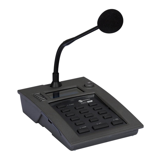
- Page 1 USER MANUAL MANUALE D’USO BM 9802 DXT 9000 DESK-TOP PAGING MICROPHONE BASE MICROFONICA DA TAVOLO PER SISTEMA DXT 9000 www.acornfiresecurity.com...
- Page 2 www.acornfiresecurity.com www.acornfiresecurity.com...
-
Page 3: Table Of Contents
www.acornfiresecurity.com TABLE OF CONTENTS INDICE ENGLISH SAFETY PRECAUTIONS DESCRIPTION CONNECTION FRONT PANEL PAGING MICROPHONE SETTINGS (display menu) SPECIFICATIONS ITALIANO AVVERTENZE PER LA SICUREZZA DESCRIZIONE COLLEGAMENTO PANNELLO FRONTALE IMPOSTAZIONI DELLA BASE MICROFONICA (tramite menù sul display) UTILIZZO DATI TECNICI www.acornfiresecurity.com... -
Page 4: Safety Precautions
RCF S.p.A. will not assume any responsibility for the incorrect installation and / or use of this product. -
Page 5: Description
All paging microphones also have the ‘Push To Talk’ (PTT), the ‘General Call’ and the ‘Chime’ (On/Off) buttons. Up to eight BE 9808 keyboards can be linked to every BM 9802 (not used for emergency purposes). Each BE 9808 has eight buttons that can be set (by using the dedicated PC software) to: Select zones or zone groups. -
Page 6: Connection
COMMON FEATURES FOR COMMON FEATURES FOR BM 9802 / 9804 PAGING MICROPHONES BM 9802 / 9804 PAGING Die-cast metal enclosure with 445 mm gooseneck MICROPHONES Preamplified hypercardioid hi-quality microphone Complete self-diagnostic (EN 54-16) Powered by either the main unit bus or 24 V dc adapter Backlit LCD ‘Evacuation’... - Page 7 RJ 45 SOCKET RJ 45 PLUG POWER SUPPLY INPUT: input for the external 24 V dc adapter (500 mA, i.e. optional RCF AC AD 2405), not included. NOTE: the first paging microphone of each bus can be used for emergency purposes...
- Page 8 ADDITIONAL BE 9808 KEYBOARDS KEYBOARDS Up to eight BE 9808 (additional 8-zone-button) keyboards can be linked to every BM 9802 (each powered by an AC AD2405 adapter and not used for emergency purposes) to increase the number of available buttons. AC AD2405...
- Page 9 BE 9808 BE 9808 BE 9808 BE 9808 Link the first BE 9808 to the BM 9802 paging microphone and all BE 9808 to one another through flat cables linked to rear ports. Pay attention to the flat cable right way, indicated by its red wire (see the figure).
- Page 10 BE 9808 keyboards) can be linked to each main unit bus (PAGING IN 1 and PAGING IN 2). Every BM 9802 needs a 24 Vdc – 500 mA power supply (not included, i.e. optional RCF AC AD2405). The first paging microphone of each bus can be used for emergency purposes (required by the EN 54-16 standard).
-
Page 11: Front Panel
www.acornfiresecurity.com FRONT PANEL 0 ÷ 9 numeric keyboard for zone selection. ENTER button to confirm and either add or remove the selected zone to the displayed list. CLEAR button to cancel a zone selection not yet included in the displayed list. CHIME button: push to toggle on/off the chime (sent ALARM before an announcement). -
Page 12: Paging Microphone Settings (Display Menu)
www.acornfiresecurity.com ÷ LEDs INDICATION SILK SCREEN COLOUR (WHEN THE LED IS STEADY LIT) The paging microphone is properly powered and POWER Green operating. L/FLT Yellow Detected fault in the paging microphone. G/FLT Yellow One or more faults are detected in the system. EVAC An ‘evacuation’... - Page 13 www.acornfiresecurity.com PARAMETER FUNCTION Contrast LCD contrast adjustment. Language selection among: Language 00 English, 01 Italian, 02 German, 03 French Password Password insertion to access all parameters Mike Vol. ¹ Microphone level choice: 00 (–3 dB pad) or 01 (no gain reduction). Chime Vol.
-
Page 14: Use
www.acornfiresecurity.com Before using the paging microphone, verify if ‘Connection: ON’ and ‘Console ready’ are displayed. Choose to enable / disable the chime by pushing the CHIME button ZONE SELECTIVE OR GENERAL CALLS 1. Select a zone on the numeric keyboard and push ENTER to add it to the displayed list;... -
Page 15: Specifications
www.acornfiresecurity.com SPECIFICATIONS Type: electret Polar pattern: cardioid Output impedance: 470 Ω (1 kHz) Microphone sensitivity: – 65 dB ± 3 dB (0 dB=1V/μbar, 1 kHz) Frequency response: 50 Hz ÷ 18 kHz (– 3 dB) Dimensions: 128 x 39 x 203 mm (without gooseneck) Gooseneck length: 445.5 mm Net weight:... - Page 16 0068 RCF S.p.A. - Via Raffaello Sanzio 13, 42124 Reggio Emilia, ITALY 0068-CPR-002/2014 EN 54-16:2008 Voice alarm control and indicating equipment for fire detection and fire alarm systems for buildings DXT 9000 Provided options Audible warnings 7.6.2 Manual silencing of the voice alarm condition 7.7.2...
- Page 17 www.acornfiresecurity.com INDICE AVVERTENZE PER LA SICUREZZA DESCRIZIONE COLLEGAMENTO PANNELLO FRONTALE IMPOSTAZIONI DELLA BASE MICROFONICA (tramite menù sul display) UTILIZZO DATI TECNICI www.acornfiresecurity.com...
-
Page 18: Avvertenze Per La Sicurezza
L’installazione e l’utilizzo errati del prodotto esimono RCF S.p.A. da ogni responsabilità. AVVERTENZE PER LA SICUREZZA Secondo la norma EN 54-16 (“livello di accesso 2”), i microfoni per annunci d’emergenza... -
Page 19: Descrizione
(es. MU 9186, MX 9502, MX 9504) tramite un cavo antifiamma di tipo “J” (quattro coppie di conduttori). È possibile collegare fino a sedici basi microfoniche BM 9802 (o, in alternativa, il modello BM 9804 con 3 tasti assegnabili) a ciascun “bus” dell’unità centrale del sistema (totale: max. -
Page 20: Collegamento
FUNZIONI COMUNI FUNZIONI COMUNI ALLE BASI MICROFONICHE BM 9802 / 9804 ALLE BASI Involucro in metallo pressofuso con flessibile di lunghezza 445 mm MICROFONICHE Microfono ipercardioide preamplificato di alta qualità BM 9802 / 9804 Autodiagnosi completa (EN 54-16) Alimentazione via “bus” dell’unità centrale oppure tramite alimentatore 24 V c.c. - Page 21 | 1 | 2 | 3 | 4 | 5 | 6 | 7 | 8 | PRESA RJ 45 CONNETTORE RJ 45 POWER SUPPLY INPUT: ingresso per l'alimentatore esterno 24 V c.c. (500 mA, es. RCF AC AD 2405 opzionale), non incluso. NOTA: “...
- Page 22 Successivamente, rimontare il coperchio posteriore. PULSANTIERE PULSANTIERE ADDIZIONALI BE 9808 ADDIZIONALI BE 9808 Ogni base microfonica BM 9802 (se non usata per funzioni d’emergenza) può essere espansa con massimo otto pulsantiere aggiuntive BE 9808 (ciascuna con otto tasti addizionali). AC AD2405...
- Page 23 (vedere la figura). BM 9802 BE 9808 BE 9808 Fissare la prima BE 9808 alla BM 9802 (e tutte le BE 9808 tra loro) usando l'apposita piastrina (inclusa nell'imballo della pulsantiera BE 9808) e quattro viti. 9802 9808 www.acornfiresecurity.com...
- Page 24 BM 9802 (con o senza pulsantiere addizionali BE 9808). Ogni BM 9802 necessita di un alimentatore 24 V c.c. – 500 mA (non incluso, es. RCF AC AD2405 opzionale). La prima base microfonica di ciascun “bus” può avere funzione d’emergenza (come da norma EN 54-16).
-
Page 25: Pannello Frontale
www.acornfiresecurity.com PANNELLO FRONTALE Tastiera numerica 0 ÷ 9 per la selezione diretta delle zone. Tasto ENTER per la conferma e l’inserimento della zona selezionata nella lista indicata sul display o la sua rimozione. Tasto CLEAR per la cancellazione della selezione di una zona non ancora inserita nella lista indicata sul display. -
Page 26: Impostazioni Della Base Microfonica (Tramite Menù Sul Display)
www.acornfiresecurity.com ÷ LED (INDICATORI LUMINOSI) SERIGRAFIA COLORE INDICAZIONE (CON LED ACCESO FISSO) POWER verde La base microfonica è alimentata correttamente e funzionante. L/FLT giallo Guasto rilevato nella base microfonica. G/FLT giallo Uno o più guasti sono presenti nel sistema. EVAC rosso Un evento d’evacuazione è... - Page 27 www.acornfiresecurity.com PARAMETRO FUNZIONE Contrasto Regolazione del contrasto del display Lingua Scelta della lingua tra 00 inglese, 01 italiano, 02 tedesco, 03 francese Password Inserimento della password per accedere a tutti i parametri Scelta livello del microfono tra: Mic Vol. ¹ 00 (attenuazione di 3 dB) oppure 01 (nessuna attenuazione) Vol.
-
Page 28: Utilizzo
www.acornfiresecurity.com UTILIZZO Prima di utilizzare la base microfonica, verificare che sul display vi siano le scritte “Connessione: ON” e “Console pronta”. Scegliere inoltre se attivare (o meno) il tono di preavviso premendo il tasto CHIME CHIAMATA SELETTIVA DELLE ZONE (O GENERALE) 1. -
Page 29: Dati Tecnici
www.acornfiresecurity.com DATI TECNICI Tipo: elettrete Direttività: cardioide Impedenza d’uscita: 470 Ω (1 kHz) Sensibilità microfono: – 65 dB ± 3 dB (0 dB=1V/μbar, 1 kHz) Risposta in frequenza: 50 Hz ÷ 18 kHz (– 3 dB) Dimensioni: 128 x 39 x 203 mm (senza flessibile) Lunghezza flessibile: 445,5 mm Peso netto:...
Need help?
Do you have a question about the BM 9802 and is the answer not in the manual?
Questions and answers