Table of Contents
Advertisement
Quick Links
Advertisement
Table of Contents

Subscribe to Our Youtube Channel
Related Manuals for Shop fox M1013


Summary of Contents for Shop fox M1013
-
Page 3: Table Of Contents
Woodstock Technical Support ....2 General .......... 26 Machine Specifications ......3 Cleaning ......... 26 Lubrication ........26 Standard Machinery Safety ..... 6 Additional Safety for General .......... 27 Metal Cutting Bandsaws ......8 Blade Change ........27 Blade Tracking ........29 Electrical Safety Instructions .... - Page 4 Woodstock International, Inc. is committed to customer satisfaction. Our intent with this manual is to include the basic information for safety, setup, operation, maintenance, and service of this product.
- Page 5 Phone #: (360) 734-3482 • Online Tech Support: tech-support@shopfox.biz • Web: www.shopfox.biz Type ..................TEFC Capacitor Start Induction Horsepower ....................... ⁄ Voltage ........................ 110/220V Prewired ........................110V Phase ........................Single Amps ........................7/3.5A Speed ........................1725 RPM Cycle ........................60 Hz Number Of Speeds ......................
- Page 6 Weight ........................150 lbs. Length ......................... 39" Width ........................23 ⁄ " Height ........................54 ⁄ " Foot Print (Length/Width) ..................26 ⁄ " x 20 ⁄ " Table ....................Precision-Ground Cast Iron Wheels ..................... Machined Cast Iron Body ........................Cast Iron Base ................Formed &...
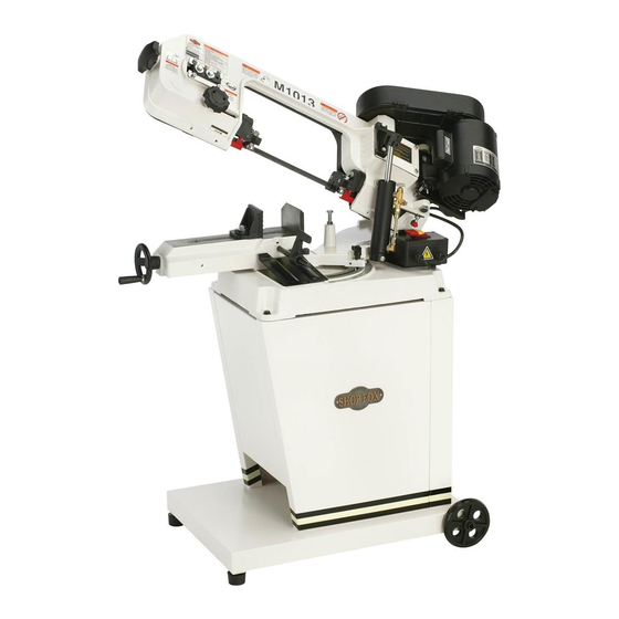
- Page 7 Blade Tension Knob Blade Tension Gauge Pulley Cover Gearbox Heavy-Duty Motor Blade Guide Knob Blade Guides Hydraulic Cylinder & Feed Rate Dial Vise Clamp Handwheel ON/OFF Push-Button Switch Assembly Cast Iron Stop Table Angle Scale Model M1013.
- Page 10 Do not operate with a dull, cracked or badly worn blade—they can break during use or greatly decrease cutting performance. Inspect blades for cracks and missing teeth before each use. Wear gloves to protect hands and safety glasses to protect eyes when replacing the blade.
-
Page 11: Extension Cords
The Model M1013 is prewired for 110V operation. For 220V operation, the motor must be re-wired as directed by the wiring diagram on the inside of the motor junction box cover. If this diagram is not available, use the wiring... -
Page 12: Inventory
" x 1" (Wheels) ....2 The following is a description of the main components —Hex Nut M8-1.25 (Feet) .....2 shipped with the Model M1013. Lay the components out to —Phillips Head Screw M6-1 x 12 ... 16 inventory them. —Flat Washer 6mm ......16 —Hex Bolt... - Page 13 The table and other unpainted parts of your This machine distributes a metal cutting bandsaw are coated with a waxy heavy load in a small footprint. Some residential floors may require additional grease that protects them from corrosion during shipment. Clean this grease off with a solvent bracing to support both machine and cleaner or citrus-based degreaser.
- Page 14 This bandsaw is shipped with four rubber feet with posts and two wheels with an axle. It is your option to install four rubber feet if you do not need to move the bandsaw, or install the axle and wheels if you need to move the bandsaw regularly.
- Page 15 Position the right panel between the front and rear panel, and secure it in place with six M6-1 x 12 Phillips head screws and 6mm flat washers, as shown With the help of an assistant or a hoisting device, place the bandsaw onto the cabinet. Installing right panel.
-
Page 16: Squaring Vise To Blade
To ensure that your bandsaw arrives without damage to the hinge system, a shipping strap was installed. After removing the shipping strap, you will have to make a Shipping Brace series of adjustments, beginning with the feed stop bolt. Remove the shipping strap hex bolt and strap with a 12mm wrench, as shown in Adjust the feed stop bolt and jam nut with a 14mm Removing shipping strap. - Page 17 The chip tray directs small workpieces into a bucket when the cut is complete. The cast iron stop allows you to repeat cuts at the same length. Position the chip tray, as shown in Insert the stop rod approximately ⁄ "...
- Page 18 After you have removed the shipping strap and have adjusted the headstock stop bolt, you must adjust the OFF button lever stop bolt, so the bandsaw shuts OFF automatically when a cut is complete. Stop Bolt & Jam Nut With the headstock in the complete down position, loosen the 12mm stop bolt and jam nut shown in Push down on the OFF button lever so the button is OFF Button...
-
Page 19: Pulley Cover
When opened, the pulley cover gives you access to change the pulley ratio so the bandsaw can cut at one of three speeds. Positioning the pulley cover. Position and rotate the pulley cover into place, as shown in Install the two ⁄... -
Page 20: Blade Tension
Proper blade tension is essential to long blade life, straight cuts, and efficient cutting. Cylinder Two major signs that you do not have proper blade Lock Pin tension are: 1) the blade stalls in the cut and slips on the wheels, and 2) the blade frequently breaks from being too Safety tight. -
Page 21: Blade Guides
The blade guide side bearings support and twist the Blade Guide Support Bearing Guide blade straight so the blade will enter the workpiece Bearing perpendicular to the table surface (see Figure ). The Adjustment blade guide support bearings prevent blade twist by Hex Bolt stopping the blade from being pushed back during a cut. -
Page 22: Test Run
Once the assembly is complete, test run your machine to make sure it runs properly. If, during the test run, you cannot easily locate the source of an unusual noise or vibration, stop using the machine immediately, then review the If you still cannot remedy a problem, contact our Tech Support at (360) 734-3482 for assistance. - Page 23 This machine will perform many types of operations that are beyond the scope of this manual. Many of these operations can be dangerous or deadly if performed incorrectly. The instructions in this section are written with the understanding that the operator has the necessary knowledge and skills to operate this machine.
- Page 24 Adjust the cast iron stop for duplicate cuts and Lock Lever install the ejector chute if required. Loosen the headstock lock lever ( ), and swivel the headstock to the needed angle of cut, and lock the lever in place. Set the blade guide so the guides hold the blade close to the workpiece, and the blade will not twist with a cutting load (refer to...
- Page 25 The Model M1013 has these three blade speeds: 80, 120, These suggested blade speeds and 200 FPM. are an average for both High Carbon Blades and Bimetal Blades. Refer to your saw blade manufac- turer for exact speeds. DISCONNECT BANDSAW FROM POWER! Determine the best speed for your cut.
-
Page 26: General
The chart below is a basic starting point for choosing blade type based on teeth per inch (TPI) for variable tooth pitch blades and for standard raker type bimetal blades/HSS blades. Measure the material thickness. This However, for exact specifications of bandsaw measurement is the length of cut blades, contact the blade manufacturer. - Page 27 The speed at which the saw blade will cut through a workpiece is controlled by blade type and feed rate. The feed rate is controlled by the valve lever and feed rate dial on the hydraulic cylinder shown in Feed Rate Dial Turning the valve lever in-line with the piping, as shown in the...
-
Page 28: Operation
Regular periodic maintenance on your machine will ensure its optimum performance. Make a habit of inspecting your machine each time you use it. Loose mounting bolts. Missing or leaking rubber toggle switch boots. Worn or damaged cords, switches, or plugs. Damaged V-belt. - Page 29 If you require additional machine service not included in this section, please contact Woodstock International Technical Support at (360) 734-3482 or send e-mail to: Change the blade when it becomes dull, damaged, or when you are using materials that require a blade of a certain type or tooth count.
- Page 30 Loosen the tension knob and slip the blade off of the wheels. Install the new blade through both blade guide bearings and around the bottom wheel (see the example in Hold the blade around the bottom wheel with one hand and slip it around the top wheel with the other hand, keeping the blade between the blade guide bearings.
- Page 31 The blade tracking has been properly set at the factory. The tracking will rarely need to be adjusted if the Blade bandsaw is used properly. Tension Knob Hex Bolts DISCONNECT BANDSAW FROM POWER! 4mm Set Raise the headstock and lock it in place by pushing Screw in the safety stop knob.
- Page 32 These pages are current at the time of printing. However, in the spirit of improvement, we may make changes to the electrical systems of future machines. Study this diagram carefully. If you notice differences between your machine and these wiring diagrams, call Woodstock International Technical Support at (360) 734-3482.
- Page 33 wiring diagram Read Page 30 Before Wiring Wire number Wire number Wire Color Wire Color Wire number Wire number Wire Color Wire Color -31-...
-
Page 34: Blade Speed
This section covers the most common problems and corrections with this type of machine. Machine does not start or a 1. Plug/receptacle is at fault or wired 1. Test for good contacts; correct the wiring. breaker trips. incorrectly. 2. Start capacitor is at fault. 2. -
Page 35: Blade Selection
Blades break often. 1. Blade is not tensioned correctly. 1. Check to see that blade is not excessively tight or too loose. 2. The workpiece is loose in the vise. 2. Clamp the workpiece tighter, or use a jig to hold the workpiece. - Page 36 -34-...
- Page 37 REF PART # DESCRIPTION REF PART # DESCRIPTION XM1013001 MOTOR 1/2HP 110/220V 1PH XPN08 HEX NUT 3/8-16 XM1013001-1 MOTOR FAN COVER XM1013018 BRACKET XM1013001-2 MOTOR FAN XM1013019 HANDLE XM1013001-3 CAPACITOR COVER XPCAP97 CAP SCREW 1/2-12 X 2-1/2 XM1013001-4 S CAPACITOR 200M 125V XPN13 HEX NUT 1/2-13 XM1013002...
- Page 38 -36-...
- Page 39 PART # DESCRIPTION PART # DESCRIPTION XM1013100 BODY FRAME XPN02 HEX NUT 5/16-18 XPB41 HEX BOLT 1/2-12 X 1-1/2 XM1013134 MOTOR MOUNT PLATE XM1013104 GEAR BOX GASKET XM1013135 KNOB BOLT 5/16-18 X 1-3/4 XM1013105 PLATE XPB07 HEX BOLT 5/16-18 x 3/4 XPVA23 V-BELT A-23 XPW07...
- Page 40 -38-...
-
Page 41: Stand Assembly
PART # DESCRIPTION PART # DESCRIPTION XM1013200 BASE XM1013220 PLATE XPB26M HEX BOLT M8-1.25 X 30 XPCAP30 CAP SCREW 5/16-18 X 1/2 XPLW04M LOCK WASHER 8MM XPS04 PHLP HD SCR 1/4-20 X 1/2 XM1013204 SCALE 223A XM1013223A BRACKET W/NUT V2.01.08 XM1013208 EJECTOR PLATE XPSS03... -
Page 42: Guides & Shafts
guides and shafts -40-... - Page 43 PART # DESCRIPTION PART # DESCRIPTION 300V2 XM1013300V2 REAR BLADE WHEEL V2.06.09 XPLW04 LOCK WASHER 3/8 301V2 XM1013301V2 BUSHING V2.06.09 XM1013319 WORM GEAR SHAFT 302V2 XM1013302V2 BLADE WHEEL SHAFT V2.06.09 XM1013322 SPECIAL PIN 10 X 40MM 303V2 XM1013303V2 AXLE BLOCK V2.06.09 XM1013323 GUIDE ECCENTRIC XPRP39M...
- Page 44 REF PART # DESCRIPTION REF PART # DESCRIPTION XM1013400 MACHINE ID LABEL XPLABLE-14B ELECTRICITY LABEL XM1013401 SAFETY GLASSES LABEL XPPAINT-1 SHOPFOX WHITE TOUCH-UP PAINT XM1013402 DISCONNECT POWER LABEL XM1013123-1 BLADE TENSION LABEL XM1013403 AMPUTATION HAZARD LABEL XPLABEL-12A READ MANUAL LABEL XPPAINT-7 SHOPFOX BLACK TOUCH-UP PAINT -42-...
- Page 46 FOLD ALONG DOTTED LINE Place Stamp Here FOLD ALONG DOTTED LINE TAPE ALONG EDGES--PLEASE DO NOT STAPLE...
Need help?
Do you have a question about the M1013 and is the answer not in the manual?
Questions and answers