Table of Contents
Advertisement
Quick Links
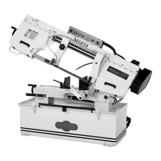
Model M1054
***IMPORTANT UPDATE***
Applies to Models Mfd. Since 6/20,
Manual Insert Printed 10/10,
and Owner's Manual Revised 8/07
Phone #: (360) 734-3482 • Tech Support: techsupport@woodstockint.com • Web: www.woodstockint.com
We made the following changes to this machine since the manual was printed:
•
The saw bow and blade covers changed to allow for the mounting of two limit switches.
Aside from the information contained in this update, all other content in the owner's manual is appli-
cable and MUST be read and understood for your own safety.
IMPORTANT: Keep this update with the owner's manual for future reference. If you have any further
questions, contact our Technical Support.
Revised Parts Breakdown
82
81
80
79
84
84-2
84-1
REF PART #
DESCRIPTION
76
XM1054076
FRONT LIMIT SWITCH KEY
77
XM1054077
REAR LIMIT SWITCH KEY
78
XM1054078
BUTTON HD CAP SCR M4-.5 X 12
79
XM1054079
REAR LIMIT SWITCH BRACKET
80
XM1054080
PHLP HD SCR M5-.8 X 10
81
XM1054081
CAP SCREW M4-.7 X 12
82
XM1054082
HEX NUT M4-.7
83
XM1054083
FRONT LIMIT SWITCH BRACKET
84
XM1054084
REAR LIMIT SWITCH SQ3
COPYRIGHT © AUGUST, 2020 BY WOODSTOCK INTERNATIONAL, INC.
WARNING: NO PORTION OF THIS MANUAL MAY BE REPRODUCED IN ANY SHAPE OR FORM WITHOUT
#21273CS
READ THIS FIRST
225V2
77
214V2
78
THE WRITTEN APPROVAL OF WOODSTOCK INTERNATIONAL, INC.
82
83
85-1
REF
PART #
DESCRIPTION
84-1
XM1054084-1
LIMIT SWITCH KEDU QKS8
84-2
XM1054084-2
LIMIT SWITCH CORD 18G 2W 60"
85
XM1054085
FRONT LIMIT SWITCH SQ2
85-1
XM1054085-1
LIMIT SWITCH KEDU QKS8
85-2
XM1054085-2
LIMIT SWITCH CORD 18G 2W 60"
214V2
XM1054214V2
SAW BOW V2.06.20
222V2
XM1054222V2
BLADE COVER V2.06.20
225V2
XM1054225V2
REAR BLADE COVER V2.06.20
81
80
85
85-2
222V2
76
Printed in Taiwan
78
Advertisement
Table of Contents

Related Manuals for Shop fox M1054


Summary of Contents for Shop fox M1054
- Page 1 READ THIS FIRST Model M1054 ***IMPORTANT UPDATE*** Applies to Models Mfd. Since 6/20, Manual Insert Printed 10/10, and Owner's Manual Revised 8/07 Phone #: (360) 734-3482 • Tech Support: techsupport@woodstockint.com • Web: www.woodstockint.com We made the following changes to this machine since the manual was printed: •...
- Page 2 Model M1054 (Mfd. Since 6/20) Electrical Safety Instructions These pages are current at the time of printing. However, in the spirit of improvement, we may make changes to the electrical systems of future machines. Compare the manufacture date of your machine to the one stated in this manual, and study this section carefully.
- Page 3 Model M1054 (Mfd. Since 6/20) (Replaces Page 32 in Manual) Electrical Components Figure 41. Downfeed limit switch (SQ1). Figure 44. Front cover limit switch (SQ2). Read Page 2 STOP Before Wiring Figure 45. Rear cover limit switch (SQ3). Figure 42. Junction box (M1).
- Page 4 Model M1054 (Mfd. Since 6/20) (Replaces Page 33 in Manual) Model M1054 220V Wiring Diagram 220V 60Hz 220V TC 24V FU1 2A Read Page 2 STOP Before Wiring LEGEND M1 = Main Motor M2 = Pump Motor KM1 = Contactor Main Motor...
- Page 5 Phone #: (360) 734-3482 • Online Tech Support: tech-support@shopfox.biz • Web: www.shopfox.biz The Model M1054 is the same machine as the Model M1048 except for improvements to the headstock, belt tension mechanism, vise, and other small changes. The Data Sheet and parts breakdowns in this insert replace the corresponding sections in the M1048 manual.
- Page 6 Model M1054 (Mfg. Since 4/10) MACHINE SPECIFICATIONS © Woodstock International, Inc. • Phone #: (360) 734-3482 • Web: www.shopfox.biz MOdEl M1054 10" x 18" METAl CuTTINg bANdSAw Product Dimensions: Weight ..........................705 lbs. Length/Width/Height ....................67 ⁄ x 24 ⁄ x 41 ⁄...
- Page 7 Model M1054 (Mfg. Since 4/10) Cutting Capacities Angle Cuts ........................45–90 deg. Vise Jaw Depth ........................12 in. Vise Jaw Height ........................5 in. Max. Capacity Rectangle Width at 90° ..................18 in. Max. Capacity Rectangle Height at 90° ..................10 in.
- Page 8 Model M1054 (Mfg. Since 4/10) Parts Breakdown 59-12 59-11 59-9 122-5 122-1 59-1 122-3 59-2 59-8 122-2 122-4 122-6 59-6 59-7 59-3 59-4 59-10 72-1 59-5 72-4 132-1 72-3 72-2 214-2 214-1 53-1 214-5 214-6 54 53 58-1 214-4 214-3...
- Page 9 Model M1054 (Mfg. Since 4/10) 345-1 341-1 610-1 611-1 613-8 613-7 612-1 613-6 613-5 613-4 613-2 613-3 613-1 625-6 625-5 625-4 625-3 625-7 625-2 625-1 0 5 4...
- Page 10 Model M1054 (Mfg. Since 4/10) Parts List REF PART # DESCRIPTION PART # DESCRIPTION XM1054005 MODEL NUMBER LABEL 59-9 XM1054059-9 CUTTING FLUID HOSE 1/4"ID X 52" XM1054006 MACHINE ID LABEL 59-10 XM1054059-10 CUTTING FLUID HOSE 1/4"ID X 12-1/2" XM1054007 BLADE TENSION LABEL...
- Page 11 Model M1054 (Mfg. Since 4/10) PART # DESCRIPTION PART # DESCRIPTION XM1054214 SAW BOW XM1054317 214-1 XM1054214-1 PIPE CONNECTOR 1/2 NPT XM1054318 BLADE GUIDE ARM 214-2 XM1054214-2 CUTTING FLUID HOSE XPW04M FLAT WASHER 10MM 214-3 XM1054214-3 RUBBER FOOT M8-1.25 X 40...
- Page 12 Model M1054 (Mfg. Since 4/10) PART # DESCRIPTION PART # DESCRIPTION XPN03M HEX NUT M8-1.25 613-4 XPLW02 LOCK WASHER 1/4 XPSS16M SET SCREW M8-1.25 X 10 613-5 XM1054613-5 SUPPORT ROD XM1054374 ANGLE SCALE 613-6 XM1054613-6 DISTANCE SET BRACKET XPS05M PHLP HD SCR M5-.8 X 8 613-7 XPN02M HEX NUT M10-1.5...
- Page 13 MODEL M1048 10" X 18" METAL CUTTING BANDSAW OWNER'S MANUAL Phone: (360) 734-3482 • Online Technical Support: tech-support@shopfox.biz COPYRIGHT © JULY, 2006 BY WOODSTOCK INTERNATIONAL, INC. REVISED AUGUST, 2007 (TR) WARNING: NO PORTION OF THIS MANUAL MAY BE REPRODUCED IN ANY SHAPE OR FORM WITHOUT THE WRITTEN APPROVAL OF WOODSTOCK INTERNATIONAL, INC.
- Page 14 ����������������������������������������������������������������������� �������������������������������������������������������������� ���������������������������������������������������������������������� �������������������������������������������������������������������� ������������������������ ����������������������������������������������������������������������� ������������������������������������������������������������������������ ������������������������������������������������������������������� ����������������������������������������������������������������� ���������������������������������������������������������������������� ����������������������������������������������� ���������������������������������������������������������������� �������������������������������������������������������������������� ������� �������������������������������������������������������������������� ����������������������������������������������������������������������� ���������������������������������������������������������������������� ������������������������������������� �� ���������������������������� �� ������������������������������������������������������������������ �� ���������������������������������������������������� ������������������������������������������������������������������ ������������������������������������������������������������������ �������������������������������������������������������������������� ��������������������������������������������������������������������� ��������������������������...
-
Page 15: Table Of Contents
Contents INTRODUCTION ....................3 Woodstock Technical Support ................3 Specifications ....................3 Control Panel ....................5 SAFETY ......................6 Standard Safety Instructions ................6 Additional Safety Instructions for Bandsaws ............8 ELECTRICAL ......................9 220V Operation ..................... 9 Extension Cords .................... 9 Grounding ....................9 SETUP ...................... - Page 16 MAINTENANCE ....................24 General .....................24 Cleaning ....................24 Lubrication ....................24 SERVICE ......................26 Troubleshooting ...................26 Blade Change ....................28 Blade Tension & Tracking ................29 Blade Guide Bearings ..................30 Squaring Blade to Table ..................31 Electrical Components ...................32 Model M1048 220V Wiring Diagram ..............33 Blade Guides Parts Breakdown ................34 Blade Guides Parts List ...................35 Drive Wheel Parts Breakdown ................36...
-
Page 17: Introduction
M1048 10" x 18" Metal Cutting Bandsaw INTRODUCTION Woodstock Technical Support Your new SHOP FOX 10" x 18" Metal Cutting Bandsaw has been specially designed to provide many ® years of trouble-free service. Close attention to detail, ruggedly built parts and a rigid quality control program assure safe and reliable operation. - Page 18 M1048 10" x 18" Metal Cutting Bandsaw Controls and Features Figure 1. M1048 Machine Identification. A. Blade Tension Handwheel B. Lift Handle C. Vise Handwheel D. Coolant Drip Pan E. Work Stop F. Pulley Cover G. Control Panel H. Blade Guide Scale Blade Guide Knob Coolant Valve Control K.
-
Page 19: Control Panel
M1048 10" x 18" Metal Cutting Bandsaw Control Panel Figure 2. M1048 control panel. A. Coolant Pump Switch: Turns the coolant pump ON. B. EMERGENCY STOP/OFF Button: Interrupts power to the system and turns the motor OFF. Twist the button until it pops out to re-energize the system. -
Page 20: Safety
M1048 10" x 18" Metal Cutting Bandsaw SAFETY READ MANUAL BEFORE OPERATING MACHINE. FAILURE TO FOLLOW INSTRUCTIONS BELOW WILL RESULT IN PERSONAL INJURY. Indicates an imminently hazardous situation which, if not avoided, WILL result in death or serious injury. Indicates a potentially hazardous situation which, if not avoided, COULD result in death or serious injury. - Page 21 M1048 10" x 18" Metal Cutting Bandsaw 10. NEVER LEAVE WHEN MACHINE IS RUNNING. Turn power off and allow all moving parts to come to a complete stop before leaving machine unattended. 11. DO NOT USE IN DANGEROUS ENVIRONMENTS. DO NOT use machinery in damp, wet locations, or where any flammable or noxious fumes may exist.
-
Page 22: Additional Safety Instructions For Bandsaws
M1048 10" x 18" Metal Cutting Bandsaw Additional Safety Instructions for Bandsaws READ and understand this USE this and other machinery with caution entire instruction manual and respect. Always consider safety first, before using this machine. as it applies to your individual working Serious personal injury conditions. -
Page 23: Electrical
M1048 10" x 18" Metal Cutting Bandsaw ELECTRICAL 220V Operation The Model M1048 is wired for 220V operation. Always connect this machine to a dedicated circuit (wire, break- er, plug, receptacle) with a verified ground, using the Electrocution or severe shock could recommended circuit size and plug/receptacle listed at occur if machine is not grounded. -
Page 24: Setup
® Inventory SUFFOCATION HAZARD! The following is a description of the main components Immediately discard all shipped with the SHOP FOX Model M1048. Lay the com- ® plastic bags and pack- ponents out to inventory them. ing materials to elimi-... -
Page 25: Machine Placement
M1048 10" x 18" Metal Cutting Bandsaw Machine Placement Cleaning Machine • Floor Load: This machine distributes a The table and other unpainted parts of your heavy load in a small footprint. Some Bandsaw are coated with a waxy grease that residential floors may require additional protects them from corrosion during shipment. -
Page 26: Mounting To Shop Floor
M1048 10" x 18" Metal Cutting Bandsaw Mounting to Shop Floor Although not required, we recommend that you mount your new machine to the floor. Because this is an optional step and floor materials may vary, floor mount- ing hardware is not included. Generally, you can either bolt your machine to the floor or mount it on machine mounts. -
Page 27: Moving & Placing Unit
M1048 10" x 18" Metal Cutting Bandsaw Moving & Placing Unit The Model M1048 comes with lifting brackets installed on the base. Use a forklift and straps rated for the machine weight to lift the machine off the pallet and onto a suit- Model M1048 able location (see Figure 8). -
Page 28: Chip Tray
M1048 10" x 18" Metal Cutting Bandsaw Chip Tray The chip tray fits over the lip of the base as illustrated in Figure 11. Figure 11. Chip tray installation. Figure 12. Feed stop. -14-... -
Page 29: Test Run
M1048 10" x 18" Metal Cutting Bandsaw Test Run Complete this process once you have familiarized yourself with all instructions in this manual. To test run the bandsaw, do these steps: 1. Read the entire instruction manual. 2. Make sure all tools and foreign objects have been Projectiles thrown from the machine removed from the machine. -
Page 30: Operations
M1048 10" x 18" Metal Cutting Bandsaw OPERATIONS General The Model M1048 will perform many types of operations that are beyond the scope of this manual. Many of these operations can be dangerous or deadly if performed incorrectly. The instructions in this section are written with the understanding that the operator has the necessary knowl- edge and skills to operate this machine. - Page 31 M1048 10" x 18" Metal Cutting Bandsaw The vise can be adjusted to cut any angle from a straight 90 degree cut-off, to a 45 degree angle by loosening the Vise Lock Handle two vise lock handles. Positive stops at 90° and 45° allow you to quickly return the rear jaw to either angle.
-
Page 32: Blade Guide Arms
M1048 10" x 18" Metal Cutting Bandsaw Blade Guide Arms The blade guide bearings are mounted on the front and Knob rear arms. The rear arm is adjustable and should be set as close to the workpiece as possible. This will help ensure straight cuts by keeping the blade from twisting and drift- ing off of the cut line. -
Page 33: Blade Selection
M1048 10" x 18" Metal Cutting Bandsaw Blade Selection The Model M1048 uses 129 ⁄ " x 1 ⁄ " bandsaw 2. Refer to the "Material Width/Diameter" blades. row of the blade selection chart in Figure 20 and read across to find your workpiece Selecting the right blade for the job depends on thickness you need to cut. -
Page 34: Blade Speed
M1048 10" x 18" Metal Cutting Bandsaw Blade Speed The Model M1048 has four speed settings—114, 196, 288, and 377 feet per minute (FPM). Refer to the chart on Page 19 for cutting speed recommendations by material type. To change blade speeds, do these steps: 1. -
Page 35: Coolant System
M1048 10" x 18" Metal Cutting Bandsaw 4. Look for the following signs to determine the best feed rate setting for your workpiece. • If you get warn tightly-curled shavings, that are brown to black in color, you are using too much downward pressure. -
Page 36: Cutting Fluid
M1048 10" x 18" Metal Cutting Bandsaw Cutting Fluid NEVER attempt to cut magnesium BIOLOGICAL and POISON when using soluble oils or emul- HAZARD! sions (oil-water solutions) as a cutting fluid! The water in the solution will increase the risk of an accidental magnesium-chip fire. -
Page 37: Operation Tips
M1048 10" x 18" Metal Cutting Bandsaw Operation Tips Bandsaw Accessories The following tips will help you safely and effectively operate your bandsaw, and help you get the maximum The following bandsaw accessories may life out of your saw blades. be available through your local Woodstock International Inc. -
Page 38: Maintenance
M1048 10" x 18" Metal Cutting Bandsaw -24-... - Page 39 M1048 10" x 18" Metal Cutting Bandsaw • Blade and Guides: Drop a few drops of light machine oil on the blade and the blade guides daily, especially when cutting cast iron, as no cutting fluid is recommended (see Figure 27). •...
-
Page 40: Service
M1048 10" x 18" Metal Cutting Bandsaw SERVICE Troubleshooting This section covers the most common symptoms and corrections with this type of machine. WARNING! DO NOT make any adjustments until moving parts have come to a complete stop and power is disconnected! If you require additional machine service not included in this section, please contact Woodstock International Technical Support at (360) 734-3482 or send e-mail to: tech-support@shopfox. - Page 41 M1048 10" x 18" Metal Cutting Bandsaw Bandsaw Operations SYMPTOM POSSIBLE CAUSE CORRECTIVE ACTION 1. Refer to Feed Rate on Page 20, or Changing Blade Machine loud 1. Excessive feed rate. Speed on Page 20, and adjust as required. when cutting 2.
-
Page 42: Blade Change
M1048 10" x 18" Metal Cutting Bandsaw Blade Change Tension Handle CUTTING HAZARD! Blades are sharp! Wear heavy leather gloves when handling blades to prevent cuts. Blades should be changed when they become dull, dam- aged, or when you are using materials that require a blade of a certain type or tooth count. -
Page 43: Blade Tension & Tracking
M1048 10" x 18" Metal Cutting Bandsaw Blade Tension & Tracking Proper blade tension is essential to long blade life, � � straight cuts, and efficient cutting. The Model M1048 fea- � � � � � tures a blade tension indicator to assist you with blade �... -
Page 44: Blade Guide Bearings
M1048 10" x 18" Metal Cutting Bandsaw Blade Guide Bearings The blade guide bearings are adjusted at the factory but due to shipping and storage may need adjustment. Use Figures 37 & 38 to guide you through the following steps. To adjust the blade guide bearings, do these steps: 1. -
Page 45: Squaring Blade To Table
M1048 10" x 18" Metal Cutting Bandsaw Squaring Blade to Table This adjustment has been made at the factory and should not need to be adjusted under normal circumstances. However, if you find the saw is not cutting square, you may need to adjust the blade. Only make this adjustment after factors such as excessive feed rate or the blade guide being set too far away from the workpiece have been ruled out. -
Page 46: Electrical Components
M1048 10" x 18" Metal Cutting Bandsaw Electrical Components Figure 43. Control panel wiring. Figure 41. Limit switch (SQ1). Figure 44. Pump motor wiring and Figure 42. Junction box (M1). capacitor(M2). (TC) Transformer (KM-1) (KM-1) Contactor Relay (KM-2 Relay Fuse (FU) Figure 45. -
Page 47: Model M1048 220V Wiring Diagram
M1048 10" x 18" Metal Cutting Bandsaw Model M1048 220V Wiring Diagram �� �� �� ���� �� ���� � � ������ � ����� � � ��� ��� ����� Disconnect power to the � machine before performing any electrical work, ser- �... -
Page 48: Blade Guides Parts Breakdown
M1048 10" x 18" Metal Cutting Bandsaw Blade Guides Parts Breakdown -34-... -
Page 49: Blade Guides Parts List
M1048 10" x 18" Metal Cutting Bandsaw Blade Guides Parts List PART�# DESCRIPTION PART�# DESCRIPTION XM1048101 SLIDE�SET XM1048157 PLASTIC�BUSHING 101-1 XM1048101-1 SLIDE XPSB04M CAP�SCREW�M6-1�X�10 101-2 XM1048101-2 SPECIAL�SET�SCREW XPLW02 LOCK�WASHER�1/4 101-3 XPN10 HEX�NUT�7/16-20 XM1048160 HEX�NUT�M8 101-4 XPW04M FLAT�WASHER�10MM XPLW01 LOCK�WASHER�5/16 101-5 XPSB134M CAP�SCREW�M10-1.5�X�65 XM1048163... -
Page 50: Drive Wheel Parts Breakdown
M1048 10" x 18" Metal Cutting Bandsaw Drive Wheel Parts Breakdown -36-... -
Page 51: Drive Wheel Parts List
M1048 10" x 18" Metal Cutting Bandsaw Drive Wheel Parts List PART�# DESCRIPTION REF PART�# DESCRIPTION XM1048216 GEAR�BOX�ASSY XPSS20M SET�SCREW�M8-1.25�X�8 XM1048217 PIVOT�SHAFT D3664 BLADE�129-3/8"�X�1�X�.035�5-8�VP XPSB72M CAP�SCREW�M10-1.5�X�30 XM1048256 DRIVE�WHEEL XM1048219 DRIVE�WHEEL�BOX XPK61M KEY�7�X�7�X�30 XPR05M EXT�RETAINING�RING�15MM XM1048258 WHEELCOVER XPSS09M SET�SCREW�M8-1.25�X�20 XM1048259 SPEED�LABEL XPSB130M CAP�SCREW�M10-1.5�X�16 XPS68M... -
Page 52: Main Parts Breakdown
M1048 10" x 18" Metal Cutting Bandsaw Main Parts Breakdown -38-... -
Page 53: Main Parts List
M1048 10" x 18" Metal Cutting Bandsaw Main Parts List PART�# DESCRIPTION PART�# DESCRIPTION XM1048330 SPRING�COVER XM1048387 POSITION�SET�BRACKET XPB26M HEX�BOLT�M8-1.25�X�30 XPW07 FLAT�WASHER�5/16 XPW07 FLAT�WASHER�5/16 XPSB14M CAP�SCREW�M8-1.25�X�20 XPN03M HEX�NUT�M8-1.25 XM1048390 GREASE�NIPPLE XPW01 FLAT�WASHER�1/2 XM1048391 BUSHING XPN13 HEX�NUT�1/2-13 XPW04 FLAT�WASHER�7/16 XM1048336 SPRING�BRACKET XM1048395 BASE XPB15M... -
Page 54: Main Parts List
M1048 10" x 18" Metal Cutting Bandsaw Main Parts List PART�# DESCRIPTION PART�# DESCRIPTION XPSB30M CAP�SCREW�M6-1�X�45 XPSS01M SET�SCREW�M6-1�X�10 XPB22M HEX�BOLT�M8-1.25�X�50 XM1048470 HOSE�W/TUBE�FITTING XM1048443 CHIP�TRAY XM1048471 HOSE�W/TUBE�FITTING XM1048446 COOLANT�TANK XM1048472 VALVE XM1048447 COOLANT�PUMP XPB03M HEX�BOLT�M8-1.25�X�16 XPW06 FLAT�WASHER�1/4 XPW07 FLAT�WASHER�5/16 XPS07 PHLP�HD�SCR�1/4-20�X�3/8 XM1048475 CYLINDER�ASSY XM1048450... -
Page 55: Label Placement
M1048 10" x 18" Metal Cutting Bandsaw Label Placement Safety labels warn about machine hazards and how to prevent machine damage or injury. The owner of this machine MUST maintain the original location and readability of all labels on this machine. - Page 56 Warranty SHOP FOX Woodstock International, Inc. warrants all machinery to be free of defects from work- ® manship and materials for a period of two years from the date of original purchase by the original owner. This warranty does not apply to defects due directly or indirectly to misuse, abuse, negligence or accidents, lack of maintenance, or reimbursement of third party expenses incurred.
- Page 57 2. How long have you been a woodworker/metalworker? _____ 0-2 Years _____ 2-8 Years ____ 8-20 Years _____ 20+ Years 3. How many of your machines or tools are Shop Fox ® _____ 0-2 _____ 3-5 ____ 6-9 _____ 10+ 4.
- Page 58 FOLD ALONG DOTTED LINE Place Stamp Here WOODSTOCK INTERNATIONAL INC. P.O. BOX 2309 BELLINGHAM, WA 98227-2309 FOLD ALONG DOTTED LINE TAPE ALONG EDGES--PLEASE DO NOT STAPLE...
Need help?
Do you have a question about the M1054 and is the answer not in the manual?
Questions and answers