
Subscribe to Our Youtube Channel
Related Manuals for Omron 3G3AX-MX2-PRT-E


Summary of Contents for Omron 3G3AX-MX2-PRT-E
- Page 1 Cat. No. I111E-EN-02 MX2/RX PROFIBUS Option Board Model: 3G3AX-MX2-PRT-E 3G3AX-RX-PRT-E USER’S MANUAL...
-
Page 2: Notice
No patent liability is assumed with respect to the use of the information contained herein. Moreover, because OMRON is constantly striving to improve its high-quality products, the information contained in this manual is sub- ject to change without notice. Every precaution has been taken in the preparation of this manual. Nevertheless, OMRON assumes no responsibility for errors or omissions. - Page 3 For the remainder of this manual, both the 3G3AX-MX2-PRT-E PROFIBUS Option Board as the 3G3AX-RX-PRT-E PROFIBUS Option Board will be referred as Option Board or Unit. The MX2 and RX Inverters will be referred as Inverter. In case information is especially for the MX2 or for the RX Inverter, a clear notification will be included for which the note is meant.
-
Page 4: Warranty And Limitations Of Liability
WAY CONNECTED WITH THE PRODUCTS, WHETHER SUCH CLAIM IS BASED ON CONTRACT, WARRANTY, NEGLIGENCE, OR STRICT LIABILITY. In no event shall the responsibility of OMRON for any act exceed the individual price of the product on which liability is asserted. -
Page 5: Disclaimers
PROGRAMMABLE PRODUCTS OMRON shall not be responsible for the user's programming of a programmable product, or any consequence thereof. Disclaimers CHANGE IN SPECIFICATIONS Product specifications and accessories may be changed at any time based on improvements and other reasons. It is our practice to change model numbers when published ratings or features are changed, or when significant construction changes are made. -
Page 7: Table Of Contents
OMRON Product References ........ - Page 8 Table of contents APPENDIX A Glossary ............APPENDIX B Parameter Process Data Object Modules .
-
Page 9: Safety Messages
Hazardous High Voltage Safety Messages Read this manual and the warning labels attached to the Inverter carefully, before you start to install and operate the Inverter. Please follow the instructions exactly. Keep this manual handy for quick reference. Definitions and Symbols A safety instruction (message) includes a "Safety Alert Symbol"... - Page 10 General Precautions - Read These First! !WARNING This equipment should be installed, adjusted, and serviced by qualified elec- trical maintenance personnel familiar with the construction and operation of the equipment and the hazards involved. Failure to observe this precaution could result in bodily injury. !WARNING Wiring, maintenance or inspection must be performed by authorized person- nel.
-
Page 11: Installation Precautions
It is extremely important that the Unit is used for its specified purpose and under the specified conditions, especially in applications that can directly or indirectly affect human life. You must consult your OMRON representative before using it in a system in the above-mentioned applications. - Page 12 Application Precautions !WARNING Failure to observe these precautions could lead to serious or possibly fatal injury. Always read these precautions. • Check any user program in the system that acts as a PROFIBUS master before actually running it. Not checking the program may result in unex- pected operation.
-
Page 13: Operating Environment Precautions
Operating Environment Precautions !Caution Do not operate the Inverter with a mounted Option Board in the following loca- tions (doing so may result in malfunction, electric shock or burning): • Locations subject to direct sunlight • Locations subject to temperatures or humidity outside the range specified in the specifications •... - Page 14 Compliance with EC Directives...
-
Page 15: Getting Started
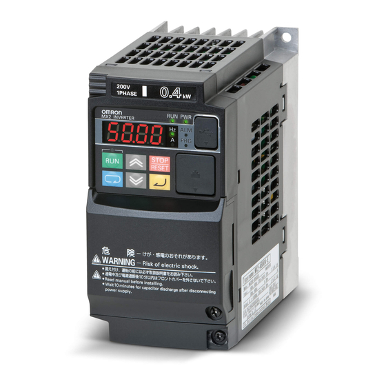
Getting Started Introduction 1-1-1 Main Features The Option Board 3G3AX-MX2-PRT-E and the 3G3AX-RX-PRT-E allow con- trolling, monitoring and parameterization of an Inverter via a PROFIBUS net- work. The Option Board serves as a gateway that passes communicated register values from the PROFIBUS network to the Inverter and vice versa. - Page 16 Introduction Section 1-1 1-1-2 Inverter Support 1-1-2-1 Inverter support for the MX2 The 3G3AX-MX2-PRT-E Option Board supports the MX2 Inverter with mini- revision AAAA. Inverter that supports 3G3AX-MX2-PRT-E Option Board can be recognized from the Inverter type label. Please check that your Inverter type label displays revision characters in the bottom right corner where the is displayed in this illustration.
-
Page 17: Option Board Specifications
Option Board Specifications Section 1-2 Option Board Specifications Table 1 Option Board Specifications Item Specification Unit type MX2 Series Option Card Model Option Board Installation MX2 Dimensions (W x H x D) 68 x 58 x 45 mm Weight 170g (typical) Unit type RX Series Option Card Model... -
Page 18: Introduction To Profibus
Introduction to PROFIBUS Section 1-3 Table 1 Option Board Specifications (continued) Item Specification Master Class 1 – Slave Set_Prm Chk_Cfg Slave_Diag Data_Exchange cyclic services Get_Cfg Rd_Inp Rd_Outp Global-Control (SYNC/UNSYNC, FREEZE/UNFREEZE & CLEAR) Master Class 1 – Slave Not supported acyclic services Master Class 2 –... - Page 19 Introduction to PROFIBUS Section 1-3 1-3-3 What is PROFIdrive The PROFIdrive device profile supplements the PROFIBUS standard. It defines a unified behavior and technique to access Inverter and drive device data. All drives supporting the PROFIdrive profile respond the same way to control instructions.
- Page 20 Introduction to PROFIBUS Section 1-3...
-
Page 21: Option Board Mounting And Installation
Orientation to Option Board Features Section 2-1 SECTION 2 Option Board Mounting and Installation Orientation to Option Board Features 2-1-1 Unpacking and Inspection Take a few moments to unpack your new Option Board and perform these steps: 1. Look for any damage that may have occurred during transportation. 2. - Page 22 Orientation to Option Board Features Section 2-1 2-1-2 Main Physical Features underside Option board connector LED indicators (RUN, ERR, BF, COMM) Warning label Fieldbus connector Grounding cable Housing Mounting screw Option Board Inverter connector LED indicators (RUN, ERR, BF, COMM) Option Board Cable Fieldbus connector Grounding cable...
-
Page 23: Basic System Description
Basic System Description Section 2-2 Four LED indicators (B) allow easy diagnosis. An attached grounding cable (E) is sized to reach the ground terminals on all Inverter models. A feature in the housing (F) will retain the mounting screw (G) when the Option Board is not mounted to the Inverter. -
Page 24: How To Mount The Option Board On The Inverter
How to mount the Option Board on the Inverter Section 2-3 How to mount the Option Board on the Inverter !HIGH VOLTAGE Always Switch OFF the mains power supply to the Inverter before removing any covers. Wait for the time specified on the Inverter front cover for the capacitors to discharge. - Page 25 How to mount the Option Board on the Inverter Section 2-3 2-3-1 Mounting sequence of the Option Board on the MX2 Inverter Step 1 Loosen the screw of the option board cover, remove the cover and put the cover aside. Step 2 For Inverters up to 4.0 kW only: loosen the screws of the terminal...
- Page 26 How to mount the Option Board on the Inverter Section 2-3 Step 4 If removed in Step 2, mount the termi- nal cover again and tighten the screw(s). Step 5 Push the Option Board into the previ- ous location of the option board cover until it clicks into place Step 6 Press down on the indicated corner...
- Page 27 How to mount the Option Board on the Inverter Section 2-3 Step 8 Secure the Option Board in place with the mounting screw (do not over- tighten). Step 9 Select the right warning language from the warning label sheet and replace the English warning if appropriate.
- Page 28 Inverter (Also referenced in this paragraph). Step 3 Configure the Inverter without Digital Operator: •Use the OMRON CX-Drive tool, or •Use PROFIdrive DP-V1 Parameter Channel to access the parameters directly (refer to APPENDIX E PROFIdrive DP-V1 Parameter Chan- nel).
- Page 29 How to mount the Option Board on the Inverter Section 2-3 Step 2 Cut out the 2 plastic break-outs from the Front Cover. Make sure no sharp edges remain. Step 3 Remount the Front Cover and tighten the screws Step 4 Purpose: mount the Inverter Connector (no.1) of the Option Board onto the interface connector (no.5) of...
- Page 30 How to mount the Option Board on the Inverter Section 2-3 Step 5 Move the Option Board Cable (no.2) to the left with your finger, so the Option Board Cable is not pinched between the Option Board and the Inverter Front Cover. Note Prevent a pinched Option Board Cable, as shown in position A.
- Page 31 How to mount the Option Board on the Inverter Section 2-3 Step 6 Press down carefully the two locking pins (no. 1) of the Option Board. Press carefully the top of the Option Board in the Inverter. Check the Option Board is being locked by the locking pins (no.1).
-
Page 32: Section 3
How to mount the Option Board on the Inverter Section 2-3 Step 8 Unscrew the mounting screws of the Terminal cover nearly completely from the plastic rings (no.1). Remount the Terminal cover under the Option Board onto the Inverter (no.2). Tighten the two screws (no.1). - Page 33 How to mount the Option Board on the Inverter Section 2-3 If the desired parameters of the Inver- Step 11 ter have been set succesfully, discon- nect the 3G3AX CAJOP300-EE cable or straight EtherNet cable from the Inverter. Push the blind cover (no.1) into place. Note Refer to section 2 in the RX User's Manual (Cat.
- Page 34 How to mount the Option Board on the Inverter Section 2-3 Note 2 The 9-pin sub-D connector uses #4/40 UNC thread for mechanical fixation of the cable connector. Always use PROFIBUS connectors. !Caution Do not use PROFIBUS connectors with a 90° cable outlet (Such connectors place unnecessary strain on the Option Board connector).
- Page 35 How to mount the Option Board on the Inverter Section 2-3 Table 6 Option Board Dimensions on the RX Inverter Item Dimension Item Dimension Item Dimension 35.1 mm 43.9 mm 31.7 mm 79.8 mm 66.5 mm 32.7 mm 66.1 mm 48.1 mm...
- Page 36 How to mount the Option Board on the Inverter Section 2-3...
-
Page 37: Configuring Drive Parameters And Option Board
Configuring the Option Board Section 3-1 SECTION 3 Configuring Drive Parameters and Option Board Configuring the Option Board All Option Board parameters are stored in the Inverter. This allows for easy replacement of the Option Board without the need to re-configure. After con- necting the Option Board to an Inverter for the first time however, proceed with the following steps: Step 1... - Page 38 Configuring the Option Board Section 3-1 Table 9 Configuration of PROFIBUS parameters (continued) Param Description Setting P045 Action on Network Set to 0 for inverter trip Error Set to 1 for deceleration and trip Set to 2 for no action Set to 3 for stop due to free-run Set to 4 for deceleration and stop P181...
- Page 39 Configuring the Option Board Section 3-1 Apply the source selection parameters according the following table for the RX Option Board. Param Description Setting P033 Torque Command For Option Board as source: Source Set to 7 (Use Option Board register) if P182 equals 1 Set to 3 (Use P034) if P182 equals 0 or 2 P036...
-
Page 40: Configuring The Network
Alternatively, P180 in Step 3 may be performed using the set-slave address functionality of your PROFIBUS master or diagnostic tool. Alternatively, Step 2 up to Step 6 may be performed using OMRON CX-Drive. Alternatively, Step 7 may be performed by resetting the Option Board using PNU972 (Refer to APPENDIX F Option Board Parameters). - Page 41 Flexible (10 words output and input) [Appendix D] Step 7 Uncheck the Enable DPV1 option on the DPV1 tab before proceeding to Step 7 if you are using OMRON CX-Configurator. Step 8 Save and download the configuration to your PROFIBUS master. Step 9...
- Page 42 Configuring the Network Section 3-2...
-
Page 43: Operations And Monitoring
Section SECTION 4 Operations and Monitoring This section provides some common usage examples to help you get started. Unless otherwise specified, all usage examples make use of the PROFIdrive device profile and associated modules (Refer to section 3-1 Configuring the Option Board, Step 1). -
Page 44: Source Selection
Source Selection Section 4-1 Table 15 Input Process Area Note 1 Depending on your source selection, CS may already be 1 on your setup. Note 2 For compatibility, some unsupported bits in ZSW are always 1. Check the Inverter settings for proper Inverter behavior before actually oper- !Caution ating the Inverter remotely via the PROFIBUS network. -
Page 45: Operating The Motor
Operating the Motor Section 4-2 Operating the Motor 4-2-1 Starting the Motor Step 1 Set the En bit to enable controlled acceleration and deceleration of the motor. Step 2 Set the Run bit to put the Inverter in run mode. The RUN indicator on the Inverter should light up at this point. -
Page 46: Jog Operation
Operating the Motor Section 4-2 4-2-3 Stopping the Motor - Controlled Step 5 Clear the Run bit to bring the motor to a controlled stop. Table 20 Output Process Area for Controlled Stop The motor decelerates, and comes to a stop. The FA bit clears as soon as the Run bit is cleared. -
Page 47: Customising The Process Area
Customising the Process Area Section 4-3 Table 23 Input Process Area with Motor Jogging Forward Note 1 To jog the motor in reverse, set the JR bit. 4-2-6 Frequency Reference and Output Frequency Scaling HSW and HIW are signed word registers. Using normal scaling, you will therefore not be able to set HSW higher than 327.67 Hz (327.68 Hz in reverse). - Page 48 If you want to use a DINT to write or read an Inverter double-word register, you will have to swap the high- and low-word in your PLC program (For dou- ble-words, an OMRON PLCs does not use the same word-order convention than the Inverter).
- Page 49 Customising the Process Area Section 4-3 4-3-2 Mapping Coil Data 0 Modbus coils 0000h though 000Fh offer a large amount of functionality. The intelligent input terminal overrides (Coils 0007h though 000Dh) for example can be used to control any of the Inverter's assignable input terminal func- tions.
- Page 50 Customising the Process Area Section 4-3 Step 4 Set parameter C001=52 (ATR: permission of torque command input) to use intelligent input terminal 1 as torque enable. Prepare the Inverter for torque mode: • Set parameter A044=3 to enable Sensorless Vector Control (SLV). •...
- Page 51 Customising the Process Area Section 4-3 Table 33 Output Process Area Configured with Forward Torque Command The motor either accelerates or decelerates depending on the load. The out- put frequency is limited by the P039 setting. The output torque is given by d012 (input PZD4).
-
Page 52: Faults And Trips
Faults and Trips Section 4-4 • Only map a Modbus registers in the output process area if it is writeable. A register is writeable if it has an 'R/W' or a 'W' in the 'R/W' column in sec- tion B-4-2 of the MX2 Inverter user's manual. •... -
Page 53: Accessing Parameters
Accessing Parameters Section 4-5 Table 36 Input Process Area with Inverter Tripped Note 1 Notice that the Inverter trips with an E12, the Flt bit is set and the Rdy bit cleared. 4-4-2 Clearing a Trip In the event that the Inverter trips, be sure to investigate the cause of this trip !WARNING thoroughly before clearing the trip. - Page 54 Note If you want to use a DINT to write or read PWE, you will have to swap the high- and low-word in your PLC program (For double-words, an OMRON PLCs does not use the same word-order convention than PROFIBUS).
- Page 55 Accessing Parameters Section 4-5 Set AK to the desired task. The parameter processing message mailbox is triggered by a change in the parameter processing output area. By first setting AK=0, you avoid uninten- tionally starting a write task when you start changing PNU, IND and PWE. 4-5-1-1 Accessing Option Board Parameters Option Board parameters are addressed by writing the parameter number to...
- Page 56 Accessing Parameters Section 4-5 Step 4 Storing changed parameter(s): To store changed parameter(s) in non-vola- tile memory, write a 1 to Option Board parameter 971: Table 44 Parameter Processing Message Area-Initiating NV Store Change WORD parameter value task Write Parameter number 971 Output area [hex] 2 0000 0001...
- Page 57 Accessing Parameters Section 4-5 The following example demonstrates how to use the parameter process mes- sage area to access Inverter Parameters: Step 1 Reading an Inverter parameter: To read Inverter parameter P180 (PROFI- BUS node address): Table 48 Parameter Processing Message Area-Reading P180 Read element value in array task Parameter number 180 Parameter group P@@@...
- Page 58 MSAC2_Initialize, MSAC2_Write, MSAC2_Read and MSAC2_Abort mes- sages make use of slot 0, index 47. Note The OMRON web-site (http://industrial.omron.eu) provides function blocks that automate parameter access when using the CJ1W-PRM21 / CS1W- PRM21 version 3.0 or newer. These function blocks automate the DP-V1 Class 2 related commands to the PROFIBUS master as well as the DP-V1 parameter channel request and response formats.
- Page 59 Accessing Parameters Section 4-5 4-5-2-2 DP-V1 read/write sequence The following illustration demonstrates the DP-V1 read/write sequence. 1. The PROFIBUS master generates an MSAC2_Write request with param- eter instructions. The write instructs the Option Board to either read or change a number of parameters. 2.
- Page 60 Accessing Parameters Section 4-5 Table 52 DP-V1 Class 2 Write-Parameter Read Instruction PNU965 Word offset Description Request Header Parameter Address REF RT Message [hex] 03C5 0000 data [dec] Request reference Option Board param 965 (user parameter) Address value (non-array) Parameter read instruction Addressing a value No of parameter addresses to follow Inverter attached to Option Board...
- Page 61 Accessing Parameters Section 4-5 Table 56 DP-V1 Class 2 Write-Array Change Instruction PNU915.3-915.4 Word offset Description Request Parameter Address Value data R RT D N PA C PNU DATA Message [hex] 03 02 01 01 10 02 0393 0003 42 02 1F01 1622 data [dec] 3 2 1 1 16 2...
- Page 62 Accessing Parameters Section 4-5 Step 5 Instruct the Option Board to change parameter 972 first to 2, then to 1 (reset the Option Board): Table 60 DP-V1 Class 2 Write-Multi-parameter Change Instruction PNU972 Word offset Description Request Header REF RT DO Message [hex] data...
- Page 63 Accessing Parameters Section 4-5 Table 61 DP-V1 Class 2 Write-Parameter Read Instruction P180 Word offset Description Request Header Parameter Address REF RT Message [hex] 3F34 0000 data [dec] 16180 Request reference Parameter P180 (user parameter) Address value (non-array) Parameter read instruction Addressing a value 1 parameter address to follow Inverter attached to Option Board...
- Page 64 Accessing Parameters Section 4-5 Table 65 DP-V1 Class 2 Write-Parameter Read Instruction F002 Word offset Description Request Header Parameter Address REF RT Message [hex] 1772 0000 data [dec] 6002 Request reference Parameter F002 (user parameter) Address value (non-array) Parameter read instruction Addressing a value 1 parameter address to follow Inverter attached to Option Board...
- Page 65 Accessing Parameters Section 4-5 4-5-2-5 Processing an Error Response When the Option Board is unable to execute one of the read parameter instructions, it adds an error value to the result data. Reading parameters A001, A166 and P033 for example: Table 69 DP-V1 Class 2 Write-Parameter Read Instruction Bad Parameter Word offset Description...
-
Page 66: Flexible Mode
Flexible Mode Section 4-6 When the Option Board is unable to execute one of the write parameter instructions, it adds an error value and the failed element index to the result data. Changing Option Board parameter elements 915.9 - 915.12 for exam- ple: Table 71 DP-V1 Class 2 Write-Parameter Change Instruction Bad Parameter Word offset... - Page 67 Flexible Mode Section 4-6 • When selecting the device profile when configuring the Option Board (Step 1 of section 3-1 Configuring the Option Board), select the Flexible device profile by setting P182 to 2. • When choosing the module while configuring the network (Step 6 of sec- tion 3-2 Configuring the Network), select the Flexible module.
- Page 68 Flexible Mode Section 4-6 A revision AAAA MX2 Inverter allows the motor to run immediately if a trip !WARNING condition is reset, and at the same time, Opr (Coil data 0) is set. For safe operation clear Opr (Coil data 0) when you detect that InvStat A changes to 8. Refer to section 1-1-2 Inverter Support to determine the MX2 Inverter revi- sion.
-
Page 69: Limitations Caused By Inverter Mode And Rating Selection
Limitations Caused by Inverter Mode and Rating Selection Section 4-7 Always clear the Opr bit in your PLC program when Inverter status A is set to !WARNING 8 (Tripping) by the Inverter. Not doing so may result in the motor starting unexpectedly when the trip is cleared. - Page 70 Limitations Caused by Inverter Mode and Rating Selection Section 4-7...
-
Page 71: Troubleshooting And Maintenance
Troubleshooting using the LED indicators Section 5-1 SECTION 5 Troubleshooting and Maintenance Troubleshooting using the LED indicators The four LED indicators on the Option Board provide information on the Option Board mode and status and the network status. When an error occurs, the Option Board indicator pattern provides trou- bleshooting information. - Page 72 Troubleshooting using the LED indicators Section 5-1 Do not clear the trip before you are finished troubleshooting an error. When you clear the trip, the error code is cleared from the four-digit display. The trip history can however be read back using d080 through d086. This will allow you to diagnose the error even if you accidentally cleared the trip cause.
- Page 73 Your Inverter version has not been prop- Reset the Inverter to factory defaults. If the erly verified with this version of the problem persists, contact your local OMRON Option Board (The PROFIBUS node representative for assistance. address in the Inverter is invalid or absent).
- Page 74 FIBUS network also have the same node address? • Is the PROFIBUS master ON-LINE? • If you are using OMRON CX-Configurator: Make sure that the 'Enable DPV1 option' on the 'DPV1' tab is NOT checked. The PROFIBUS wiring is not correct.
- Page 75 Troubleshooting using the LED indicators Section 5-1 Table 81 PROFIBUS Errors (continued) Possible Cause(s) Corrective Action Display & Display & Indicators Indicators The PROFIBUS configuration is NOT cor- Check (and correct) the following items: rect, but the PROFIBUS master can com- •...
-
Page 76: Troubleshooting Using Profibus Diagnostics
• Are you using the correct GSD file in your PROFIBUS master configuration pro- gram? • If you are using OMRON CX-Configurator: Is the 'Enable DPV1 option' on the 'DPV1' tab checked? Invalid slave response The PROFIBUS master is not compatible with Check (and correct) the following items: the specification of the Option Board. - Page 77 Troubleshooting Using PROFIBUS Diagnostics Section 5-2 Table 82 Standard diagnostic information (continued) Diagnostic Status Possible Cause(s) Corrective Action Station not ready The Option Board is still starting up. If the problem persists, replace the Option Board. Station not existent The PROFIBUS wiring is not correct. Check (and correct) the following items: •...
- Page 78 Node storage failed Your Inverter version has not been properly Contact your local OMRON representative for verified with this version of the Inverter. assistance. Invalid option parame- Your Inverter version has not been properly...
-
Page 79: Maintenance And Inspection
Maintenance and Inspection Section 5-3 Maintenance and Inspection 5-3-1 How to replace the MX2 Option Board !HIGH VOLTAGE Always Switch OFF the mains power supply to the Inverter before removing the Option Board. Wait for the time specified on the Inverter front cover for the capacitors to discharge. - Page 80 Maintenance and Inspection Section 5-3 Step 4 Unscrew and remove the faulty Option Board grounding cable. Keep the screw and washers, but set the faulty Option Board aside. 3-phase 200 V 5.5 - 15 kW 1-phase 200 V 0.1 - 2.2 kW 3-phase 400 V 5.5 - 15 kW 3-phase 200 V 0.1 - 3.7 kW 3-phase 400 V 0.4 - 4.0 kW...
- Page 81 Maintenance and Inspection Section 5-3 Step 8 Press down on the indicated corner of the replacement Option Board housing to ensure proper connection of the Option Board connector Step 9 Check that there is no gap between the top edges of the replacement Option Board Inverter casing.
- Page 82 Maintenance and Inspection Section 5-3 5-3-2 How to replace the RX Option Board !HIGH VOLTAGE Always Switch OFF the mains power supply to the Inverter before removing the Option Board. Wait for the time specified on the Inverter front cover for the capacitors to discharge.
- Page 83 Maintenance and Inspection Section 5-3 Step 4 Unscrew the Option Board grounding cable, mounted with an Inverter grounding bold. Step 5 Gently pull the Option Board straight out while pushing down on the indi- cated spots to release the snap-fits.. Be careful not to stress the flex cable Step 6 Remove the flex cable from the...
- Page 84 Maintenance and Inspection Section 5-3 Then align the larger hole on the Inverter connector (no.3) with the threaded hole (no.6) in the Inverter. Push the Inverter connector into place. Step 8 Move the Option Board Cable (no.2) to the left with your finger, so the Option Board Cable is not pinched between the Option Board and the Inverter Front Cover.
- Page 85 Maintenance and Inspection Section 5-3 Step 9 Press down carefully the two locking pins (no. 1) of the Option Board. Press carefully the top of the Option Board in the Inverter. Check the replacement Option Board is being locked by the locking pins (no.1).
-
Page 86: Warranty
RX Inverter. Warranty OMRON's exclusive warranty is that the products are free from defects in materials and workmanship for a period of one year (or other period if speci- fied) from date of sale by OMRON. -
Page 87: Appendix A Glossary
The output frequency of an Inverter is variable and proportional to the attained motor speed. Intelligent Terminal A configurable input or output logic function on the Omron Inverters. Each ter- minal may be assigned one of several functions. Inverter A device that electronically changes DC to AC current through an alternating process of switching the input to the output, inverted and non-inverted. - Page 88 APPENDIX A PROFIBUS PROFIBUS (PROcess FieldBUS) is a standard for Fieldbus communication in automation technology PROFIBUS DP PROFIBUS DP (PROFIBUS for Decentralised Peripherals) is an implementa- tion of PROFIBUS optimized for distributed I/O applications. PROFIBUS DP devices can co-exist with non-DP PROFIBUS devices on the same bus. PROFIBUS FMS PROFIBUS FMS (PROFIBUS Fieldbus Message Specification) is an imple- mentation of the PROFIBUS tailored for demanding communication tasks.
-
Page 89: Parameter Process Data Object Modules
APPENDIX B APPENDIX B Parameter Process Data Object Modules The Parameter Process Data Object (PPO) modules implement the cyclic data exchange mapping for the PROFIdrive device profile. Five modules are supported (PPO1 - PPO5) allowing you to select the number of exchanged registers and PKW messaging support. -
Page 90: I/O Mapping
I/O Mapping APPENDIX B I/O Mapping Table B-1 PPO format I/O Mapping Word Offset Content PPO1 PPO2 PPO3 PPO4 PPO5 Output Area Input Area Task ID and Parameter num- Task ID and Parameter num- PNU index / Parameter PNU index / Parameter group in high byte group in high byte High word of value... -
Page 91: Control And Status Words - Stw/Zsw
Control and Status Words - STW/ZSW APPENDIX B Control and Status Words - STW/ZSW Note The PZD1 output and input registers will control STW and present ZSW only if P160 = 0 and P170 = 0 Table B-2 PPO format STW/ZSW mapping STW (Control Output Word) ZSW (Status Input Word) Name... -
Page 92: Parameter Processing Message Area - Pkw
Parameter Processing Message Area - PKW APPENDIX B Parameter Processing Message Area - PKW The PKW Message Area provides an interface to read and change Inverter or Option Board parameters using the I/O Data Exchange area. Several tasks support reading and changing different parameter types and sizes. A failed task is accompanied by error code detail to simplify diagnosis. -
Page 93: Appendix C Conventional Modules
APPENDIX C Conventional Modules Conventional modules are provided for backward-compatibility with previous OMRON Inverter products. Three modules are supported: Basic Data, Extended Data 1 and Extended Data 2. Note Set P182 = 1 for the Option Board to support the Conventional modules... -
Page 94: Extended Data 2 I/O Mapping
Extended Data 2 I/O Mapping APPENDIX C Note The Torque Compensation only becomes effective if: P036 = 5, A044 = 3 and ATR is assigned to a digital input and turned on. Re- fer to MX2 User Manual section 3-9-4. Note The Analog Output Channel 1 only becomes effective if: C028 = 16. -
Page 95: Extended Data 1 Digital Output Register
Extended Data 1 Digital Output Register APPENDIX C Table C-4 Conventional control status regs (continued) Operation Command Inverter Status Name Description Name Description 1: ON Trip Status 1: Inverter is tripped Intelligent Input 0: Inverter not tripped 0: OFF Terminal override [8] External Trip (EXT) 0 to 1: Trip inverter... -
Page 96: Modbus Message Area
Modbus Message Area APPENDIX C Table C-6 Ext1 digital output reg for RX Digital Outputs Name Description Output Terminal 15 0: OFF 1: ON Alarm Relay Output Terminal 0: OFF 1: ON Modbus Message Area Table C-7 Conventional modbus mailbox Byte Offset Output Area Input Area... -
Page 97: Appendix D Flexible Module
APPENDIX D APPENDIX D Flexible Module The Flexible Format implements I/O data exchange that supports direct map- ping of Inverter Modbus registers in the I/O area. This offers fieldbus- and pro- file-independent control of the Inverter. The exchanged registers are configured by setting Inverter registers P160 - P179 to the appropriate Inverter Modbus addresses. - Page 98 APPENDIX D Table D-1 Flexible format I/O mapping Word Content Offset Output Area Input Area Modbus register set by P168 Modbus register set by P178 Ignored if P168 = 0 Ignored if P178 = 0 Modbus register set by P169 Modbus register set by P179 Ignored if P169 = 0 Ignored if P179 = 0...
-
Page 99: Profidrive Dp-V1 Parameter Channel
(MSAC2) Messaging connection. Please consult the documentation of your PROFIBUS Master with regard to support for- and usage of a DP-V1 Class 2 Messaging connection. (Version 3.0 and newer of the OMRON CJ1W-PRM21 and CS1W-PRM21 supports this. Special instructions can be obtained from an Omron representative.) -
Page 100: Read Parameter Request
Read Parameter Request APPENDIX E Read Parameter Request Table E-1 PROFIdrive V4 Parameter read request Word Offset Contents High byte Low byte Request Header Parameter Address + (LEN-3) Parameter Address + (LEN-2) + (LEN-1) Request reference (Typically incremented by user program) Request type: 01h: Parameter read instruction Drive object:... -
Page 101: Read Parameter Response
Read Parameter Response APPENDIX E Read Parameter Response Table E-2 PROFIdrive V4 Parameter read response Word Offset Contents High byte Low byte Response Header Parameter Value(s) or Error Num- ber matching 1 Parameter DATA Address requested + (DL + (LEN-DL Parameter Value(s) or Error Num- ber matching N Parameter... -
Page 102: Change Parameter Request
Change Parameter Request APPENDIX E Change Parameter Request Table E-3 PROFIdrive V4 Parameter change request Word Offset Contents High byte Low byte Request Header Parameter Address + (3N-1) Parameter Address + (3N) + (3N+1) + (3N+2) Parameter Value(s) matching 1 Parameter Address + (3N+3) DATA... -
Page 103: Change Parameter Response
Change Parameter Response APPENDIX E Change Parameter Response Table E-4 PROFIdrive V4 Parameter change response Word Offset Contents High byte Low byte Response Header Zero Data / Error Number and Erro- neous Index matching 1 Parame- DATA ter Address requested + (DL + (LEN-DL Zero Data / Error Number and Erro-... -
Page 104: Parameter Value Formats
Parameter Value Formats APPENDIX E Parameter Value Formats Table E-5 PROFIdrive V4 Parameter data format Byte Value and Pre-condition Offset where C where C in a Change in a Request Response Response is even is odd Byte 1 Byte 1 Word 1 Double- Error... -
Page 105: Option Board Parameters
APPENDIX F APPENDIX F Option Board Parameters Table F-1 Option Board Parameters PNU R/W Res Name IND in Description Inverter Param Commissioning mode status 0: Commissioning mode NOT active 1: Commissioning mode active Set commissioning mode The number of seconds for commissioning mode to time remain active PPO Write format... - Page 106 APPENDIX F Table F-1 Option Board Parameters (continued) PNU R/W Res Name IND in Description Inverter Param Fault number of failures Failure 1 (Most recent) d081 2 .. 8 (Reserved) Failure 2 d082 10 .. 16 (Reserved) Failure 3 d083 18 ..
-
Page 107: Profidrive Error Numbers
APPENDIX G APPENDIX G PROFIdrive Error Numbers Table G-1 PROFIdrive Error Numbers Error Meaning Likely Causes number Erroneous Description fields 0000h Bad parameter number PNU is unknown 0001h Parameter value cannot be changed AK / RT PNU is not writeable 0002h Low or high limit exceeded Value / DATA Change value is outside the allowable limits... - Page 108 APPENDIX G...
-
Page 109: Appendix H Slave_Diag Message (Sap60)
APPENDIX H APPENDIX H Slave_Diag Message (SAP60) Table H-1 Slave_Diag Message (SAP60) Byte Offset Station not Station not Configura- Extended Function not Invalid slave Parameter Master lock existent ready tion fault Diagnostics suported response fault Slave deac- Freeze Static diag- Parameter (Reserved) Sync mode... - Page 110 APPENDIX H...
-
Page 111: Table Index
Table index Table 1 Option Board Specifications ........... . 3 Table 2 LED Indicators. - Page 112 Table index Table 56 DP-V1 Class 2 Write-Array Change Instruction PNU915.3-915.4 ..... . . 47 Table 57 DP-V1 Class 2 Read-Result of PNU915.3-915.4 Change Instruction ....47 Table 58 DP-V1 Class 2 Write-Parameter Change Instruction PNU971 .
-
Page 114: Revision History
Revision history A manual revision code appears as a suffix to the catalog number on the front cover of the manual. Cat. No. I112E-EN-02 Revision code The following table outlines the changes made to the manual during each revision. Page numbers refer to the previous version. - Page 116 OmRON EUROPE B.V. Wegalaan 67-69, NL-2132 JD, Hoofddorp, The Netherlands. Tel: +31 (0) 23 568 13 00 Fax: +31 (0) 23 568 13 88 www.industrial.omron.eu Austria France Norway Spain Tel: +43 (0) 2236 377 800 Tel: +33 (0) 1 56 63 70 00...
Need help?
Do you have a question about the 3G3AX-MX2-PRT-E and is the answer not in the manual?
Questions and answers