
Related Manuals for SVAT CV0204DVR


Summary of Contents for SVAT CV0204DVR
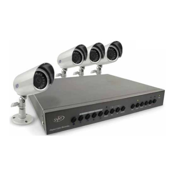
- Page 1 SVAT ELECTRONICS Now You Can See WEB READY DVR SYSTEM W/ 4 OUTDOOR COLOR NIGHT VISION SECURITY CAMERAS COMPLETE SYSTEM Instruction Manual Model # CV0204DVR www.svat.com...
- Page 2 Website: www.svat.com Warranty Terms SVAT products are guaranteed for a period of one year from the date of purchase against defects in workmanship and materials. This warranty is limited to the repair, replacement or refund of the purchase price at SVAT's option.
-
Page 3: Table Of Contents
- Instruction Manual - Mounting Hardware - Online/Toll Free Tech Support - 1 Year Warranty T IS COMP TIBLE T IS COMP TIBLE The CV0204DVR is compatible with TVs, VCRs, computers and other SVAT systems including: CVP403C CVP500C CVP3017M CV65 CVP400C CV0204DVR... -
Page 4: Safety Precautions
SVAT ELECTRONICS Now You Can See SAFETY PRECAUTIONS SAFETY PRECAUTIONS Disposal of Old Electrical & Electronic Equipment (Applicable in the European Union and other European countries with separate collection systems). This symbol on the product or on its packaging indicates that this product shall not be treated as household waste. -
Page 5: Introduction / Features
The DVR can be set to overwrite old footage when the drive does run out of space, allowing you continuous recording, year after year. The CV0204DVR also has a built-in internet server for remote viewing. Just plug the DVR into your internet connection and set it up with the included software. Then simply... -
Page 6: Camera Setup
SVAT ELECTRONICS Now You Can See 1. CAMERA SETUP 1. CAMERA SETUP Step One Locate a desired mounting location for the camera and fasten in using the included hardware. Connect the supplied wire to the wiring on the back of the camera. -
Page 7: Installation
Please setup the connection by following the illustration shown below (detailed instructions on using the network function can be found in Section 9): Plug the power cord into your DVR and plug it into an outlet. SVAT recommends plugging it into a surge protected power bar for your device's protection. -
Page 8: Name & Function Of Each Part
SVAT ELECTRONICS Now You Can See 3. NAME AND FUNCTION OF EACH P 3. NAME AND FUNCTION OF EACH P 3.1 FRONT PANEL Quad screen display. CH 1 screen display. CH 2 screen display. CH 3 screen display. CH 4 screen display. -
Page 9: Operating Procedure
SVAT ELECTRONICS Now You Can See 4. OPERA TING PROCEDURE 4. OPERA TING PROCEDURE 4.1 POWERING ON This DVR is built to be on at all times, and therefore should be connected to a surge protected power bar (UPC power backup). Use the power bar's switch to turn the unit off and on. -
Page 10: Playback Mode
SVAT ELECTRONICS Now You Can See *Note ~ CH1: No block figure next to CH1 indicates that it is not recording. EACH: Record Type QUAD: Record Type (M): MASTER HDD (T): TIMER RECORD (A): ALARM RECORD (M): MIX RECORD ( ): Currently under recording. -
Page 11: System Setup
SVAT ELECTRONICS Now You Can See 5. SYSTEM SETUP 5. SYSTEM SETUP 5.1 MENU Main Menu Menu Layer Indication: The device consists of four menu layers. : First Menu Layer (Main Menu) : Second Menu Layer : Third Menu Layer... - Page 12 SVAT ELECTRONICS Now You Can See 5.2 SYSTEM SETUP Cursor (>) position indicates the current function selected. Press the up and down buttons to move the cursor. Press ENTER button to proceed. Press MENU button to exit “System Setup”. “System Setup” is situated on the second menu layer. Under this menu layer user may setup the system time, password, return system to default value, and language preference, etc (VERSION displayed represents the FIRMWARE version).
- Page 13 SVAT ELECTRONICS Now You Can See 5.2.1 TIME SETUP Time Set - Sets the time and date on your DVR. Use the up and down arrows to select a value to change, and press ENTER to change the value. When you are finished, press MENU to return to the previous menu screen.
- Page 14 SVAT ELECTRONICS Now You Can See 5.2.2 PASSWORD SETUP Cursor (>) position indicates the current function selected. Press the up and down buttons to move the cursor. Press ENTER button to proceed. Press MENU button to exit “Password Setup”. Select MENU PASSWORD to password-protect your DVR menu from unwanted changes.
- Page 15 SVAT ELECTRONICS Now You Can See 5.2.2.1 CHANGE PASSWORD Press ENTER to show the display above. Enter the current password (CURRENT PASSWORD). Enter new password (NEW PASSWORD). Confirm the new password (CONFIRM PASSWORD). When password change is successful, the system will display “PASSWORD CHANGED”.
- Page 16 SVAT ELECTRONICS Now You Can See 5.2.3 LOAD DEFAULT Press enter on this option to return the DVR to its factory default settings. Press enter again to confirm, or menu to cancel. When the message “DVR RESET COMPLETED TURN OFF AND ON THE VCR” is displayed, restart the DVR.
- Page 17 SVAT ELECTRONICS Now You Can See 5.2.4 LANGUAGE SETUP To setup “LANGUAGE SET” function, press ENTER, to select the desired language (languages supported are Chinese and English). CV0204DVR...
- Page 18 SVAT ELECTRONICS Now You Can See 5.3 CAMERA SETUP Camera Enable - Select this option to change the camera view combination. For example, if you select (- - - -), all camera channels will be disabled, and a black screen will be displayed. If you select (1 2 3 4), all cameras channels will be enabled and displayed.
- Page 19 SVAT ELECTRONICS Now You Can See 5.3.1 CAMERA SETUP Camera Select - Select the camera channel to which you would like to make changes (CH 1-4). Record Enable - Press ENTER to switch the channel recording on/off. Motion Detection - Press ENTER to switch the motion detection function on/off.
- Page 20 SVAT ELECTRONICS Now You Can See 5.4 RECORD SETUP Record Type - Press ENTER to select between QUAD and EACH mode. QUAD mode will record all four cameras, but will not let you view each camera individually during playback. EACH mode will record all four cameras and allow you to view each camera individually during playback.
- Page 21 SVAT ELECTRONICS Now You Can See 5.4.1 RECORD MODE This menu allows you to set up the preferred type of scheduled recording (time, motion/time&motion, off) throughout a 24 hour day. For example, you may want to record continuously from 9:00 AM to 5:00 PM, but only record when motion is detected the rest of the time.
- Page 22 SVAT ELECTRONICS Now You Can See 5.5 BUZZER SETUP ALARM ALERT: Press ENTER to setup “ON” or “OFF”, whether to trigger the alarm when motion event has been detected (this setup is only active when the system is under record status and schedule record is setup to "M" (Mix).
- Page 23 SVAT ELECTRONICS Now You Can See 5.6 EVENT LIST Cursor (>) position indicates the current function selected. Press button to move the cursor to the desired item Press ENTER to proceed. Press MENU to exit “EVENT LIST” selection. “EVENT LIST” is situated on the second menu layer. Under this menu layer user may setup “TIME SERACH”...
- Page 24 SVAT ELECTRONICS Now You Can See 5.6.1 TIME SEARCH TIME SEARCH: Displays system recording time (begin and end). Press button to select the desired time and date. Press ENTER to setup playback starting time and date. Press MENU to exit “TIME SEARCH” selection.
- Page 25 SVAT ELECTRONICS Now You Can See 5.6.2 EVENT SEARCH EVENT SEARCH: Displays all recording events, every page consists of 7 events, and maximum 63 stored events. Press PLAY button to play the selected event. BEGIN: END: 05/01/15 15:00:01 05/01/15 15:00:06 Displays the beginning and end time of each event.
- Page 26 SVAT ELECTRONICS Now You Can See 5.7 HARD DRIVE SETUP When item “OVERWRITE” has been selected, press ENTER to enable overwrite when both MASTER or SLAVE HDD is full (2 options: OVERWRITE or STOP). MASTER HDD: displays the capacity of the MASTER HDD.
- Page 27 SVAT ELECTRONICS Now You Can See 5.7.1 FORMAT When proceeding “FORMAT” function, the above display will be shown. When password entered is correct, the screen will display the message “PASSWORD CORRECT”, “HDD FORMATTED” (flashes 3 times), indicating hard disk format is successful.
-
Page 28: Network Remote Control (Optional)
SVAT ELECTRONICS Now You Can See 6. NETWORK REMOTE CONTROL (OPTIONAL) 6. NETWORK REMOTE CONTROL (OPTIONAL) 6.1 NETWORK DVR SETUP Connect the RJ-45 cable to the network port on the back of the DVR, and the other end to your router. Use IPEdit.exe to test the DVR. The network access software is not MAC compatible. - Page 29 SVAT ELECTRONICS Now You Can See 6.1.2 ONLINE WITHOUT DHCP SERVER (STATIC IP) Use IPEdit.exe to find the installed Network DVR. The Internet DVR without IP allocated by DHCP will have a default IP Address of 169.254.1.13 Select this Internet DVR on the Camera List Window.
- Page 30 SVAT ELECTRONICS Now You Can See 6.2.1 ONLINE USING Setup similar to “6.1 Network DVR Setup”. 6.2.2 ONLINE USING ADSL (PPPOE) ROUTER Setup similar to “6.4.3.3 Connect to ADSL by PPPoE mode”. 6.2.3 ONLINE USING DDNS SERVER (RECOMMENDED) The DDNS service provides the dynamic IP to users to gain access to resources connected to the Internet via a cable or DSL connection.
- Page 31 SVAT ELECTRONICS Now You Can See 6.2.4.1 ONLINE CONNECTION Before entering remote connection, install ActiveX (If you are running Windows XP you most likely have it) and check your browser setup by following the procedures below: A. Open Internet Explorer under “Tools” and select “Internet Options”.
- Page 32 SVAT ELECTRONICS Now You Can See Change ActiveX settings to the ones seen above CV0204DVR...
- Page 33 SVAT ELECTRONICS Now You Can See The graphic below will be shown the first time you install the ActiveX Control. Please select "Yes" to accept installation. Download ActiveX Control Live view will be displayed when installation is successful. Live display under ActiveX mode...
- Page 34 SVAT ELECTRONICS Now You Can See 6.3 MAIN DISPLAY Remote control DVR - Main Menu Live display. DVR control button. Video setup. Configuration: Enter detail setup Recording: Displays recording setup menu (for video recording). Snapshot: Pop-up window displays live images, right mouse click to save.
- Page 35 SVAT ELECTRONICS Now You Can See 6.3.2 VIEW Two types of display method: Resizable: Adjustable image size. Actual size: The actual image size. 6.3.3 ROTATE Four types of rotate settings: Rotate 0: Default state Rotate 180: Rotate the image by 180 degrees.
- Page 36 SVAT ELECTRONICS Now You Can See 6.3.5 SAVE CURRENT PICTURE Select to save live images. 6.3.6 DVR CONTROL SETUP Supports DVR remote control function (Please refer to 6.1 Front Panel Buttons and Controls, on page 5). 6.3.7 QUALITY SETTING Network DVR provides 5 image quality settings. The user can select the quality setting from the “Quality”...
- Page 37 SVAT ELECTRONICS Now You Can See 6.3.8 RESOLUTION SETTING The network DVR provides six resolution settings. The user can select the quality setting from the “Resolution” list box. • 176 x 144 • 160 x 120 • 320 x 240 •...
- Page 38 SVAT ELECTRONICS Now You Can See • Reboot DVR: The system needs 30 seconds to reboot the DVR's network (Rebooting does not affect hard drive recording). • Firmware update (Please refer to 6.4.5). • Restore Factory Default 6.4.2 USER SETTING •...
- Page 39 SVAT ELECTRONICS Now You Can See 6.4.2.2 NEW USER / CHANGE PASSWORD Enter a new user name and password information to create a new user account, or enter an existing user account, then set a new password to replace the old password, and select “OK”...
- Page 40 SVAT ELECTRONICS Now You Can See 6.4.3.2 DHCP The “DHCP” is automatically set as the default network setting of the Network DVR. When a Network DVR is connected into the LAN, it will issue DHCP packets to request an IP address that is dynamically assigned by the DHCP server. If it is unable to get a DHCP address, the Network DVR will assign a default IP address such as “169.254.1.13”.
- Page 41 SVAT ELECTRONICS Now You Can See Note: If item "Send mail after connected" is selected, then the Network DVR will send a mail that contains the message "Dial Up IP Address/ Netmask/ Gateway/ DNS Server" will be mailed to the preset e-mail address.
- Page 42 SVAT may occasionally release newer versions of firmware for your DVR. Please check your product at www.svat.com to ensure you have the latest version. When new firmware is supplied, you may update to the new version (bin file) through your PC by following the procedures below: In the configuration menu of your network DVR, click on Firmware Update.
- Page 43 SVAT ELECTRONICS Now You Can See Firmware Update. Press "here" button (1) to update Firmware. Press "here" button (2) to delete the file. The message below displays the writing progress of the firmware update. When Firmware update is completed, it will show 100%, and a message "Click here to reboot DVR browser"...
-
Page 44: Troubleshooting
SVAT ELECTRONICS Now You Can See 7. TROUBLESHOOTING 7. TROUBLESHOOTING Problem Solution No display on television Make sure all RCA and power cables are plugged in securely and in their proper places. Make sure your television is on the correct channel (input mode). - Page 45 SVAT ELECTRONICS Now You Can See Problem Solution Unexpected Alarms (beeps) Video Loss - One of your cameras are go off. disconnected. There are a few options: connect a camera, disable that camera's channel if you don't want a camera installed in that channel, or disable the VIDEO LOSS alert alarm by going to MENU>Buzzer Setup>Video...
-
Page 46: Glossary
Firmware - The built-in software that controls the DVR's functions. Higher firmware version may be released to provide additional features. Please check this product at www.svat.com to ensure you have the latest firmware version installed. Go to Menu > System Setup to view the firmware version running on your DVR. -
Page 47: Port Forwarding
SVAT ELECTRONICS Now You Can See 9. PORT FOR ARDING YOUR ROUTER FOR USE 9. PORT FOR ARDING YOUR ROUTER FOR USE WITH NETWORK DVR WITH NETWORK DVR 1. Belkin Router 2. DLINK Wireless Router 3. LINKSYS Wireless Router 4. LINKSYS Wired Router 5. -
Page 48: Port Forwarding
SVAT ELECTRONICS Now You Can See 2. D-LINK ROUTER 2. D-LINK ROUTER The port forwarding process is dependant on the brand and model number of the router being used. Port forwarding of a router is required with your system to allow user access to your network device. - Page 49 SVAT ELECTRONICS Now You Can See Step 2: Enter the user name and password as shown below (admin by default) and press the OK button. Step 3: Select the Applications and Gaming tab. Step 4: Select the Port Range Forwarding tab.
- Page 50 SVAT ELECTRONICS Now You Can See 5. WESTELL ROUTER 5. WESTELL ROUTER The port forwarding process may vary depending on the brand and model number of the router being used. Port forwarding of a router is required to allow user access to your network device.
- Page 51 SVAT ELECTRONICS Now You Can See Step 2: Enter ‘admin’ in the User Name and ‘password’ in the Password dialog box to enter the Westell configuration page. Step 3: Select the Services button in the Security menu Step 4: In the Services menu, select the Add Custom Service button...
- Page 52 SVAT ELECTRONICS Now You Can See Step 6: In the Port Range screen, proceed as follows: In the Service Name field, type DVR In the Global Port Range field, enter in the first box, the first number of the port you need to port forward (e.g.
- Page 53 SVAT ELECTRONICS Now You Can See 9. WIRE ROUTER 9. WIRE ROUTER The port forwarding process may vary depending on the brand and model number of the router being used. Port forwarding of a router is required to allow user access to your network device.
-
Page 54: Specifications
SVAT ELECTRONICS Now You Can See 10. DVR SPECIFICA TIONS 10. DVR SPECIFICA TIONS Functionality ..........Simplex Video Compression ........Modified MJPEG Resolution ............720 x 480 Recording Frame Rate ..........Max 120 FPS Recording Time ........Max 60 days, 15 days with 4 cameras Resolution ..........Max 640 x 224... - Page 55 SVAT ELECTRONICS Now You Can See Housing Color ..........Graphite Grey Power Input ............DC 12V 2A Power Adapter Input ........AC 100-250V 50/60Hz Cooling ............Fan Based Operating Environment Temperature ..........41°F ~ 104°F Humidity ..........30 ~ 80% Dimensions ............12.6" x 1.8" x 10.6"...
- Page 56 SVAT ELECTRONICS Now You Can See Sun Shield ............Yes IR Cut Filter ............No Housing Material ..........anodized aluminum Housing Color ..........platinum silver Signal/Noise Ratio..........>48% Camera Bracket ..........Yes Operating Environment Temperature ..........-14°F ~ 122°F Humidity ..........98% Camera Power Input ........DC 9V 200mA Power Adapter Input ........120V 60Hz...
- Page 57 SVAT ELECTRONICS Now You Can See T SUPPORTS CRIME ST OPPERS T SUPPORTS CRIME ST OPPERS Crime Stoppers programs are operated as non-profit charities and are managed by a volunteer board of directors who raise funds and pay rewards to individuals who anonymously call with information that helps solve crime.
- Page 58 SVAT ELECTRONICS Now You Can See T SUPPORTS CRIME ST OPPERS T SUPPORTS CRIME ST OPPERS To receive more information about Crime Stoppers or to make a charitable donation please fill in the fields below, cut on the dotted line and mail in.
- Page 59 SVAT ELECTRONICS Now You Can See NOTES CV0204DVR...
- Page 60 SVAT ELECTRONICS Now You Can See w w w. s v a t . c o m D i s c l a i m e r S VAT d o e s n o t e n d o r s e a n y o f S VAT p r o d u c ts f o r a n y i l l e g a l a c t i v i t i e s .
Need help?
Do you have a question about the CV0204DVR and is the answer not in the manual?
Questions and answers