Table of Contents
Troubleshooting

Subscribe to Our Youtube Channel
Related Manuals for SVAT 2CV500 - 4CH


Summary of Contents for SVAT 2CV500 - 4CH
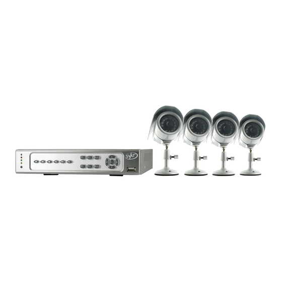
- Page 1 SVAT ELECTRONICS now you can see Web Ready 4 Channel H.264 DVR Security System w/ Smart Phone Access and 4 Hi-Res Indoor/Outdoor Night Vision Surveillance Cameras COMPLETE SYSTEM INSTRUCTION MANUAL V1.0 www.svat.com CV500 - 4CH...
- Page 2 PLEASE DO NOT RETURN THIS PRODUCT TO THE STORE Please contact a SVAT customer support representative first regarding any additional information on product features, specifications or assistance with set-up. You can contact us via one of the methods below: Email: support@svat.com Online live web chat: www.svat.com/support...
-
Page 3: Product Warranty Information
PRODUCT WARRANTY INFORMATION Please visit our website at www.SVAT.com for information about your product’s warranty. We take quality very seriously. That is why all of our products come with a one year warranty from the original purchase date against defects in workmanship and materials. If you have warranty or support issues please contact us using any of the following methods: Phone: 1.866.946.7828 Fax: 1.888.771.1701 Email: support@SVAT.com... -
Page 4: Table Of Contents
INTRODUCTION ...7 WHAT IS INCLUDED ...8 FEATURES ...8 ADDITIONAL ACCESSORIES ... 10 BUTTONS & CONNECTIONS ... 10 Front Panel ...10 Back Panel ...11 Remote Control ...11 THINGS TO CONSIDER BEFORE INSTALLATION ... 12 CAMERA INSTALLATION ... 12 Mounting ...12 Wiring ...12 CONNECTING ADDITIONAL DEVICES TO THE DVR ... - Page 5 TABLE OF CONTENTS PTZ SETUP ...19 PTZ control ... 20 MOTION DETECTION ...20 Setting Motion ... 21 Motion Detect ... 21 Buzzer ... 21 Sensitivity ... 21 Motion Area ... 21 RECORDING SETUP...22 Resolution ... 22 PPS ... 22 Alarm Record ... 23 Alarm Record Duration ...
- Page 6 TABLE OF CONTENTS Key Board Lock ... 35 ID Number ... 35 Display Setup ... 35 Language ... 36 Password ... 36 Firmware Upgrade ... 36 Load Default ... 36 Load Backup USB ... 37 Daylight Savings Time ... 37 LIVE VIEWING...
-
Page 7: Introduction
TABLE OF CONTENTS DDNS CONFIGURATION ...49 DDNS.org ... 49 DDNS Account Setup ... 50 NETWORK VIEWING AND PLAYBACK ... 51 SOFTWARE ...51 Online Software Icons ... 51 Time Point Backup ... 53 Record ... 53 Screen Information ... 53 DVR CONFIGURATION OPTIONS ...54 System Options ... -
Page 8: What Is Included
WHAT IS INCLUDED CV500 DVR 4 Indoor/Outdoor Night (500 GB HDD) Vision CCD Cameras RCA to BNC Connectors • 1-4 to one power supply cable • 10 ft power adapter for DVR • 2 window warning stickers • 1 CR2025 battery for remote •... - Page 9 FEATURES..Continued 24/7 Lifetime Live Customer Support Assistance is available whenever you need it. Simply visit www.SVAT.com for video networking guides, simple tips on how to protect your property, and instructional videos on topics such as camera placement. Our customer support team can be reached by phone 24/7, or by email and live web chat services so that you will always have access to an expert.
-
Page 10: Additional Accessories
ADDITIONAL ACCESSORIES • CLEARVU7 (LCD Monitor) Front Panel 1. Channel Display buttons – Displays each corresponding camera channel in full screen when selected 2. Quad - Displays all 4 cameras at once 3. LED indicators– Indicates what functions are on and/or working 4. -
Page 11: Back Panel
BUTTONS & CONNECTIONS...continued Back Panel 1. CH1 – Video input 1 2. CH2 – Video input 2 3. CH3 – Video input 3 4. CH4 – Video input 4 5. Monitor Out – Connect to the RCA composite video input of your TV or monitor 6. -
Page 12: Things To Consider Before Installation
THINGS TO CONSIDER BEFORE INSTALLATION CAMERA INSTALLATION • The camera should be installed between 8 and 13ft above the area to be monitored • Ensure there are no obstructions in the camera’s view, to maximize viewing area • Ensure that the sunshade is positioned to avoid glare and position camera away from direct sunlight or indoor lighting •... -
Page 13: Connecting Additional Devices To The Dvr
CAMERA INSTALLATION...continued 5. Connect the male RCA plug from the 60 ft cable to the BNC to RCA connector. 6. Repeat the above steps for all of the included cameras Note: For detailed instructions and information on the cameras incluced with this system, please refer to the Camera specifications on pg. -
Page 14: Rca Monitor
CONNECTING ADDITIONAL DEVICES TO THE DVR...continued CONNECTING A MONITOR TO THE DVR (RCA COMPOSITE) 1. Connect a BNC to RCA connector to the MONITOR OUT connection on the back of the DVR. 4. Switch the TV/Monitor source to view the DVR. Note: If the monitor has multiple video inputs then the video source will need to be switched to watch the DVR. -
Page 15: Router
CONNECTING ADDITIONAL DEVICES TO THE DVR...continued CONNECTING YOUR DVR TO THE ROUTER 1. Power off the DVR by removing the power cable from the back of the DVR. 2. Connect the included network cable to the back of the DVR in the “Ethernet” port (LAN). -
Page 16: Getting Started
GETTING STARTED Now that you have powered up the DVR and properly connected to a TV or monitor you are ready to begin using and customizing the DVR for your specific needs. The DVR will automatically begin recording once it has been powered on and initialized. Initializing the DVR is the normal start up process and can take a few moments. -
Page 17: Main Menu
MAIN MENU The main menu consists of nine options: 1. Camera Setup 2. Motion Setup 3. Record Setup 4. Alarm Setup 5. HDD Management 6. Network Setup 7. Backup Setup 8. System Setup 9. Exit MAIN MENU As you navigate through the Menu of the DVR, you will notice that most fields are adjustable. If the Menu setting has you can adjust the value by either using the left and right directional buttons, or scrolling up or down with the mouse wheel. -
Page 18: Camera Setup
MAIN MENU...continued Camera setup allows you to make adjustments to your cameras individually. A description of the adjustable fields will be found below. CAMERA 1. To choose which camera you want to work with highlight CAMERA so that the background is yellow and use the mouse wheel or directional keys to scroll to the camera you wish to adjust. •... -
Page 19: Display
MAIN MENU...continued DISPLAY You can choose whether or not to display any individual camera. By setting the display to OFF the camera will not be displayed in live viewing, however the camera channel will continue to record as per the defined recording settings. The video will be displayed during playback. DWELL TIME Dwell time refers to the amount of time the footage from a particular camera will be displayed for when you’re in auto sequence mode. -
Page 20: Ptz Control
MAIN MENU...continued PTZ Control To access the PTZ controls of the DVR you will need to use the mouse. 1. Move the mouse cursor to the bottom the screen for Pop Up Menu Bar to display. 2. Select the icon. The PTZ controls look like this: - Direction Keys –... -
Page 21: Setting Motion
MAIN MENU...continued TO SET MOTION DETECTION 1. Select the camera you wish to configure the motion detection for. 2. Use the mouse wheel, or the directional arrow buttons to toggle between on and off. MOTION DETECT Motion detection can be set to ON or OFF. When set to ON, the DVR will recognize and perform specific activities when motion is detected based on your settings. -
Page 22: Recording Setup
MAIN MENU...continued RECORDING SETUP 1. Access the Main Menu. 2. Select the Motion Setup icon. RESOLUTION: You can set the resolution to: NTSC Mode 1. 720 x 240 (max 60 PPS) 2. 360 x 240 (max 120 PPS) PAL Mode 1. -
Page 23: Alarm Record
MAIN MENU...continued ALARM RECORD PPS You can change the PPS for alarm record. You may wish to change the alarm PPS so that there is a higher PPS for when an alarm (e.g. motion) is detected by the DVR and a lower PPS for Normal Record. -
Page 24: Record Quality
MAIN MENU...continued RECORD QUALITY There are four levels of record quality you can choose from, and it is adjustable per camera if recording with 720 x 240 resolution. If using 360 x 240 resolution, camera 1 & 2 quality will be adjusted together and 3 & 4 will be adjusted together: 1. -
Page 25: Schedule Setup
MAIN MENU...continued SCHEDULE SETUP A schedule can be used to customize your recording modes by the hour for every day of the week. This is beneficial for business environments that have different hours during weekdays and the weekend. For home use, you can set different record modes for the days you have people over for housework, yard work, or even babysitters. -
Page 26: Alarm Setup
MAIN MENU...continued ALARM SETUP 1. Access the Main Menu by pressing Menu or move the mouse to the bottom of the display screen to reveal pop up Menu bar and click the Menu icon 2. Select the ALARM setup icon There are several different types of events that will trigger the Alarm Recording. -
Page 27: Video Loss Detect
MAIN MENU...continued VIDEO LOSS DETECT You can set the DVR to archive video footage when it detects video loss. Since video loss is a serious issue for camera surveillance, it is important to be able to see what happened before the video loss occurs. When video loss detection is enabled, the DVR will display on the screen or in the event log when video loss occurs. -
Page 28: Relay Time Setup
MAIN MENU...continued To Change the Buzzer Time: 1. Highlight BUZZER TIME SETUP. 2. Select to access the Buzzer Time Setup Menu. 3. Highlight the type of alarm you want to set. 4. Use the mouse wheel or directional keys to change the length of time the buzzer will sound when the alarm is detected. 5. -
Page 29: Overwrite Mode
MAIN MENU...continued OVERWRITE MODE The DVR provides you with the option to automatically overwrite the saved video and audio content on the HDD or to stop recording when the HDD is full. The default setting is ON and will automatically overwrite old footage. If the mode is set to OFF, you can set a warning to alert you when the HDD is nearing its full capacity. -
Page 30: Network Setup
MAIN MENU...continued To Setup the Password Protect: 1. Select HDD PASSWORD PROTECT. 2. Use the mouse wheel or directional keys to change from disable to enable. This will require the HDD password setup to be entered before accessing the HDD format Menu while enabled. The next step is to choose a password for the HDD format protection. -
Page 31: Terms
NETWORK SETUP...continued IP Mode: Static vs. DCHP A DCHP (Dynamic Host Configuration Protocol) address is the most common setup for home or office networks. This allows the DVR to automatically receive an IP address from the router. By default the IP MODE should be set to DHCP and this is acceptable in most situations. A static IP is one that does not change. -
Page 32: Pppoe
NETWORK SETUP...continued PPPoE SETUP (Point-to-Point Protocol over Ethernet). PPPoE is used by (A)DSL Internet connections. Usually the modem or router will store the PPPoE information so that the DVR and other computers that are connected to the network do not require a password to access the internet. -
Page 33: Backup Setup
BACKUP SETUP The DVR allows you to backup your recorded footage onto a separate and portable USB flash drive. To Setup backup Recording: 1. Insert your USB flash drive into the USB port on front of the DVR. 2. Access the Main Menu by clicking Menu or move the mouse to the bottom of the screen to reveal the pop up bar. -
Page 34: System Setup
BACKUP SETUP...continued 2. Choose the starting date and time of when to transfer the video footage. Highlight the value you wish to change and use the directional keys up and down or the mouse scroll wheel to adjust the value. 3. -
Page 35: System Type
SYSTEM SETUP...continued 4. NTP (Network Time Protocol) Mode can be enabled or disabled to allow the DVR to synchronize the date and time with a NTP server. By default the NTP server IP is set to 198.123.30.132. 5. Choose your GMT Timezone. Example: Central Time Zone = -06:00 GMT. 6. -
Page 36: Language
SYSTEM SETUP...continued LANGUAGE: This DVR allows for the following 19 languages: English, Chinese, Italian, French, Japanese, Spanish, Polish, simplified Chinese, Greek, Hungarian, Netherlands, Dutch, Portugeuse, Swedish, Finnish, Russian, Czech, Hebrew, & Ukrainian To change the on screen display language: 1. Highlight LANGUAGE. 2. -
Page 37: Load Backup Usb
SYSTEM SETUP...continued 4. Use the directional keys or the mouse to select either YES or NO. Select YES to load the factory default settings. 5. Click to save settings and return to System Set. 6. Click to save settings and return to Main Menu. Load Setup From USB This option can only be used if the DVR settings have been previously backed up to USB. -
Page 38: Live Viewing
LIVE VIEWING The following directions will tell you certain information about live viewing with the DVR, there are multiple ways to view the live footage. POP UP MENU BAR (operation) – Using the USB Mouse, the pop up menu bar allows you to view the following options. PTZ control –... -
Page 39: Playback
PLAYBACK By clicking the Play button from the Pop Up Menu, front panel, or remote control a Play Search window will pop up. The CV500-4CH allows you to review your playback with two different search options: 1. Play Time Search – Allows you to view your recorded footage based on the day and time you wish to preview. -
Page 40: Time Search
PLAYBACK...continued SEARCH BY TIME 1. Select the play button to call up the playback Menu button on the front of the DVR or the remote. 2. Highlight PLAY TIME SEARCH and select using the mouse or by pressing enter on the DVR or remote. 3. -
Page 41: Backup Video Playback
PLAYBACK...continued 6. Follow the playback controls listed earlier to view your footage. 7. To exit playback, press STOP or scroll mouse to bottom of screen and click the stop button. BACKUP VIDEO PLAYBACK Once you have backup footage onto your USB drive, you can archive that footage or view it on a computer. How to view backup footage from USB: 1. -
Page 42: Buttons And Connections
PLAYBACK...continued To begin viewing playback click the play button BACKUP PLAYER – PLAYBACK CONTROL The playback buttons are as follows from left to right: 1. STEP BACK: Pauses playback and reverses playback one frame each time it is clicked 2. REWIND: Rewinds playback 3. PAUSE: Pauses playback 4. -
Page 43: Network Guide
NETWORK GUIDE Requirements: You will need to have: • The DVR connected to a router • The router connected to the Internet • A PC or laptop that is connected to the same router that the DVR is connected to. The PC can be connected by a wired or wireless connection •... -
Page 44: Method 1
NETWORK GUIDE...continued Method 1 (Recommended): Add the DVR’s IP address to the Trusted Sites in Internet Explorer. 1. Open up Internet Explorer. 2. Click on TOOLS. 3. Click on INTERNET OPTIONS. 4. Click on the SECURITY Tab. 5. Click on TRUSTED SITES. 6. -
Page 45: Method 2
NETWORK GUIDE...continued Method 2: 1. Open up Internet Explorer. 2. Click on TOOLS. 3. Click on INTERNET OPTIONS. 4. Click on the SECURITY Tab then the CUSTOM LEVEL button. 5. Change the ActiveX settings listed below. • Download signed ActiveX controls: PROMPT or ENABLED •... -
Page 46: Login
NETWORK GUIDE...continued Log in to the DVR (Using Internet Explorer) By default the DVR will require a user to input a username and password before being able to view the DVR online. The default username and password for the web interface of the DVR is: Username: admin Password: admin... -
Page 47: Viewing Your Dvr Outside Of Your Network
NETWORK GUIDE...continued VIEWING YOUR DVR OUTSIDE OF YOUR NETWORK Now that you have successfully viewed your DVR and cameras from a computer it is time to set up your router to view the DVR while at a remote location. This process is called Port Forwarding and you can find detailed instructions on how to complete the required steps at http://portforward.com. -
Page 48: Testing
NETWORK GUIDE...continued TESTING Now that you know your external IP address, you can perform a test to ensure your DVR is accessible from outside your network (over the internet). This test should be performed by a computer that is not on the same network as the DVR. Although, using the external IP on the same network will sometimes work, it will not work in all cases and it is best to test from a remote location. -
Page 49: Ddns Configuration
NETWORK GUIDE...continued To Configure the DVR to Work with DDNS: 1. Press Menu and select NETWORK SETUP. Insert password if required. The default password is “1111”. 2. Navigate to DDNS and press ENTER. 3. Change DDNS SETTING to ENABLE. DDNS (Dynamic DNS) Instead of having to type in the IP address to access the DVR online you can use DDNS to create a easy to remember website name to access the DVR. -
Page 50: Ddns Account Setup
NETWORK GUIDE...continued DYNDNS.ORG ACCOUNT SETUP (required if using DYNDNS.ORG) 1. Open Internet Explorer and type http://www.dyndns.org in the address bar. 2. Create a new account by clicking the “Create Account” link in the top right hand corner of the site. 3. -
Page 51: Network Viewing And Playback
NETWORK VIEWING & PLAYBACK Once you have your DVR set to view online, the software to view the footage differs from the software that is in the DVR. Please refer to the following instructions when viewing live footage online. This is what the online viewing software will look like. DVR Configuration: When you click DVR configuration, it displays a Menu for you to change/review settings. - Page 52 NETWORK VIEWING & PLAYBACK...continued 6. Rec. (Record) – This will record the footage that is currently being displayed onto the desired save location on your computer. This will work in live mode or in playback mode. Press Stop to terminate the recording and view the saved footage. It will be saved in H.264 format and will require the player to view the recorded footage.
-
Page 53: Time Point Backup
NETWORK VIEWING & PLAYBACK...continued ADDITIONAL OPTIONS: You can left click the mouse on the viewing windows to call up additional options. The extra options are described below: 1. Snapshot: Will allow you to save a single picture from the image. 2. -
Page 54: Dvr Configuration Options
NETWORK VIEWING & PLAYBACK...continued DVR CONFIGURATION OPTIONS User Management Lists all the user accounts that have been added to the DVR and allows you to add more accounts onto the DVR. Anonymous User Login : Determines whether or not the DVR will prompt the user to enter a username/password when connecting to the DVR over the Internet. To add a user: Input the username, the password, confirm the password and select which user group they will be a part of. -
Page 55: Network Options
NETWORK VIEWING & PLAYBACK...continued NETWORK VIEWING & PLAYBACK...continued Load Default Load Setup From Default (Setting): Applies factory default settings. You will be prompted to confirm the restore. Load Setup From: (Browse): Load Setup From: (Setting): Backup Setup (Download): NETWORK OPTIONS IP Setting DHCP/Static: Choose whether your network uses DHCP IP address or a Static IP address. - Page 56 NETWORK VIEWING & PLAYBACK...continued DDNS Enabled/Disabled: This will enable the DVR to connect to the DDNS provider listed below. If disabled the DVR will not update the DDNS website with the current information. Provider: Choose the DDNS service provider for the DVR to connect to. See DDNS SETUP for more information on the service providers.
-
Page 57: Other Options
NETWORK VIEWING & PLAYBACK...continued FTP Server: Enter the Hostname or IP address of the FTP server. Username: A username that has the proper permissions on the FTP server to create Directories and Add files. Password: Enter the password for the username listed above. Port: Enter the port the FTP server uses. -
Page 58: Troubleshooting
3G MOBILE DEVICE PORT FORWARDING...continued From Your Mobile Device: • Open up the web browser application • Click Options and choose the option that will allow you to type in a URL • Type in rtsp://74.11.213.177/CH03 This will pull up channel 3 of your DVR if port forwarding settings are set up correctly and your phone is compatible with this DVR. MOBILE TROUBLESHOOTING IF YOU CANNOT CONNECT A great tool for testing to see if you have setup port forwarding correctly is by using the following website: http://canyouseeme.org. -
Page 59: Mobile Viewing Installation Guide
3G MOBILE DEVICE PORT FORWARDING...continued 5. Your router is blocking your computer from using the External IP Address from the same network as the DVR. Try connecting to the External IP Address from a remote computer that is not connected to the same network. 6. -
Page 60: Sony Ericson K608I Viewing
MOBILE VIEWING INSTALLATION GUIDE...continued Sony Ericsson K608i The first step is to copy the MobileViewer.jar file to a storage location on your mobile that can be accessed using the file manager on the mobile device. CV500 - 4CH 1. Copy the MobileViewer.jar file from the cd or website onto the desktop. 2. - Page 61 MOBILE VIEWING INSTALLATION GUIDE...continued Name: This is arbitrary and can be named to your liking. Host: This is the IP address for your DVR. If connecting using the 3G or other wireless network, the proper Ports must be forwarded on your router. See Port Forwarding for instructions. Ex.
-
Page 62: Iphone And Itouch Viewing
MOBILE VIEWING INSTALLATION GUIDE...continued iPhone and iTouch Viewing (Safari) Be sure that the mobile device that is connected can connect to the internet via cell phone network or Wi-Fi. If connected to the same Wi-Fi network as the DVR the iPhone can access the DVR cameras via the LAN (internal) IP address or the WAN (external) IP address. 1. Open up Safari on the iPhone or iTouch. BlackBerry (Bold) The first step is to copy the MobileViewer.jar file to a storage location on your mobile that can be accessed using the file manager on the mobile device. - Page 63 MOBILE VIEWING INSTALLATION GUIDE...continued 2. On the BlackBerry: (Setting may not be available depending on cell phone service provider) • Open up the Menu • Open Options/Settings • Open Advanced Options • Click on TCP • You must set your APN settings according to your specific Cell Phone Service Provider. Contact your cell phone service provider for the APN, APN username, and APN password 3.
- Page 64 MOBILE VIEWING INSTALLATION GUIDE...continued 5. The following will be displayed: Name: This is arbitrary and can be named to your liking. Host: This is the IP address for your DVR. If connecting using the 3G or other wireless network the proper Ports must be Forwarded on your router.
-
Page 65: Troubleshooting Guide
TROUBLESHOOTING GUIDE My DVR has no power There is no way to turn the DVR off I cannot hear recorded audio when playing back Playback video is choppy Timer recording is not working properly My PTZ camera (not included) is not working. -
Page 66: Camera Troubleshooting
TROUBLESHOOTING GUIDE CONT... Cannot view DVR on the computer The color on the camera picture is too purple, blue, etc My browser keeps freezing Camera Troubleshooting I cannot see at night with my IR night vision cameras My camera is not displaying any image My camera is being displayed in black and white... -
Page 67: Specifications
TROUBLESHOOTING GUIDE CONT... • Try replacing the power supply with a properly working camera’ s power supply Lines displayed on screen / scrolling lines • Test the camera out on a different 60ft cable set. The video signal could be getting disrupted by a different / electrical noise / interference power source. - Page 68 DVR SPECIFICATIONS cont... Play back Mode Full, Quad OSD and System Menu Display Yes OSD Language Display Multi-Language Time and Date Stamp Display Yes Password Protection Yes. Menu, Clear HDD, Online access Adjustable Screen Settings Color, Brightness, Contrast, Hue File Transfer Ethernet, USB Operating System Linux Processor...
- Page 69 CAMERA SPECIFICATIONS CAMERA SPECIFICATIONS (VU301 - C MODEL) Camera Type Weatherproof Color IR CCD Camera Image Sensor 1/4" Color SHARP CCD Resolution 420 TV Lines Outdoor Use IP Rating IP65 Focal Length 3.6mm Focus Type Fixed Optimal Focal Distance 20 ft. Night Vision Number of IR LEDs and 12, up to 15ft...
-
Page 70: Camera Manual
CAMERA MANUAL USING THE ONE TO FOUR PORT POWER SUPPLY WITH CAMERAS Wiring Diagram Wiring Instructions 1. Plug 12V adapter (A) into electrical wall outlet or surge protecting power bar. 2. Plug the single end (female 12 V connection) of the four port power supply (C) into the male end of the 12V adapter (B). 3. - Page 71 CAMERA DRILLING TEMPLATE To wall mount the camera, drill three holes using a 3/16" drill bit and the template below. Insert the supplied wall anchors into holes and secure camera to wall with supplied screws. DRILL HOLES IN THESE POSITIONS ...Tear Here...
- Page 72 CAMERA DRILLING TEMPLATE DRILL HOLES IN DRILL HOLES IN DRILL HOLES IN THESE POSITIONS THESE POSITIONS THESE POSITIONS ...Tear Here... NOTES AREA CV500 - 4CH www.SVAT.com...
- Page 73 NOTES AREA CV500 - 4CH...
- Page 74 VISIT US ON THE WEB! • Product Information • User Manuals • Quick Start Guides www.svat.com SVAT ELECTRONICS • Specification Sheets • Software Updates • Firmware Upgrades Model#: CV500-4CH www.svat.com now you can see...
Need help?
Do you have a question about the 2CV500 - 4CH and is the answer not in the manual?
Questions and answers