Table of Contents
Advertisement
Advertisement
Table of Contents

Related Manuals for Cotek SK Series


Summary of Contents for Cotek SK Series
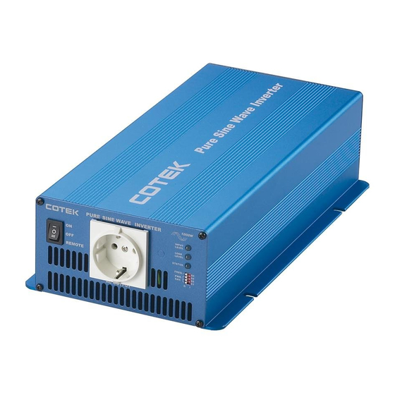
- Page 1 SK Series Pure Sine Wave Inverter User’s Manual...
-
Page 2: Table Of Contents
Contents Important Safety Instructions……………………………………………… General Safety Precautions…………………. Precautions When Working With Batteries… 2. Features…………………………………………………………………... Application………………………………..…… Electrical Performance……………..………… Mechanical Drawings………………………… 3. Introduction……………………………………………………………… Front Panel Operations……………………… 10~13 Rear Panel Operations………………….…… 14~15 Protections Features…………………….…… Installation……………………………………… Making DC Wiring Connections ………..….. 17~19 AC Safety Grounding………………………… 20~21 Inverter Operation……………………….……... -
Page 3: Important Safety Instructions
1. Important Safety Instructions 1-1. General Safety Precautions 1-1-1. Do not expose the Inverter to rain, snow, spray, bilge or dust. To reduce risk of hazard, do not cover or obstruct the ventilation openings. Do not install the Inverter in a zero-clearance compartment. - Page 4 1-2-2. Never smoke or allow a spark or flame in vicinity of battery or engine. 1-2-3. Do not drop a metal tool on the battery. The resulting spark or short-circuit on the battery of other electrical part may cause an explosion.
-
Page 5: Features
2. Features Pure sine wave output (THD < 3%) Output frequency:50 / 60Hz switch selectable Input & output fully isolation design Low power “ Power Saving Mode “ to conserve energy High efficiency 89~94% Capable of driving highly reactive & capacitive loads at start moment. Tri-Color indicators display input voltage &... -
Page 6: Electrical Performance
2-2. Electrical Performance Specification Model No. Item SK700-112 SK700-124 SK700-148 SK700-212 SK700-224 SK700-248 Continuous Output Power 700W Maximum Output Power (3Min.) 800W Surge Rating 1400W Input voltage 100 / 110 / 120V +/- 3% 220 / 230 / 240V +/- 3% Output Voltage Frequency 50 / 60Hz +/- 0.05%... - Page 7 Specification Model No. SK1000- SK1000- SK1000- SK1000- SK1000- SK1000- Item Continuous Output Power 1000W Maximum Output Power 1150W (3Min.) Surge Rating 2000W Input voltage 100 / 110 / 120V +/- 3% 220 / 230 / 240V +/- 3% Output Voltage Frequency 50 / 60Hz +/- 0.05%...
- Page 8 SK1500- SK1500- SK1500- SK1500- SK1500- SK1500- Item Continuous Output Power 1500W Maximum Output Power 1725W (3Min.) Surge Rating 3000W Input voltage 100 / 110 / 120V +/- 3% 220 / 230 / 240V +/- 3% Output Voltage Frequency 50 / 60Hz +/- 0.05% (Switch Selectable) Output Waveform Pure Sine Wave ( THD <...
- Page 9 Specification Model No. SK2000- SK2000- SK2000- SK2000- SK2000- SK2000- Item Continuous Output Power 2000W Maximum Output Power 2300W (3Min.) Surge Rating 4000W Input voltage 100 / 110 / 120V +/- 3% 220 / 230 / 240V +/- 3% Output Voltage Frequency 50 / 60Hz +/- 0.05%...
- Page 10 Specification Model No. SK3000- SK3000- SK3000- SK3000- SK3000- SK3000- Item Continuous Output Power 3000W Maximum Output Power 3450W (3Min.) Surge Rating 6000W Input voltage 100 / 110 / 120V +/- 3% 220 / 230 / 240V +/- 3% Output Voltage Frequency 50 / 60Hz +/- 0.05%...
-
Page 11: Mechanical Drawings
2-3. Mechanical Drawings... -
Page 13: Introduction
3. Introduction This power inverter series is a the member of the most advanced line of mobile AC power systems available. To get the most out of the power inverter, it must be installed and used properly. Please read the instructions in this manual before installation and operation this model. - Page 14 3-1-2. ON / OFF/ REMOTE (Main) switch: a. Before installing the inverter, make sure the main switch must be “OFF”. b. Before using the remote unit, make sure the main switch must be “ REMOTE”. 3-1-3. Input Level:Display Input Voltages LED Status DC 12V DC 24V...
- Page 15 3-1-4. Load Level:Display AC Loads (Watts) LED status DARK GREEN ORANGE BLINK 35 ~ 230 ~ 525 ~ Over SK700 0 ~ 35W 230W 525W 672W 672W 50 ~ 330 ~ 750 ~ Over SK1000 0 ~ 50W 330W 750W 960W 960W 75 ~...
- Page 16 3-1-6. Status:Display Power & Fault Status Green LED LED Signal Status Solid Power OK Blink (Slow) Power Saving - - - - - - - Red LED LED Signal Status Blink (Fast) - - - - - - - - - - - - Blink (Slow) - - - - - - - Blink...
- Page 17 3-1-8. AC outlets (available):...
-
Page 18: Rear Panel Operations
3-2. Rear Panel Operations: 3-2-1. Remote Port: The SK Series Inverter can be compatible with any of remote controllers, CR-6, CR-7 or CR-8. Before using the remote unit, make sure the main switch must “ REMOTE”. 3-2-2. Fan Ventilation: Do not obstruct, allow at least 1 inch for proper air flow. - Page 19 3-2-3. DC Input Terminals: Connect to 12V / 24V / 48V battery or the other power sources. 【+】is positive,【-】is negative. Reverse polarity connection will blow internal fuse and may damage inverter permanently. DC Input Voltage Model Minimum Maximum 12 V 10.5 15.0 24 V...
-
Page 20: Protections Features
3-3. Protections Features: Model DC Input (VDC) Over Temperature Protection Over Voltage Under Under Voltage INTERIOR HEAT SINK Voltage Shut- Restart Shut- Restart Shut- Restart Shut- Restart down Alarm down down down 15.3 14.2 11.0 10.5 12.5 30.6 28.4 22.0 21.0 25.0 deg C... -
Page 21: Making Dc Wiring Connections
3-4-6. Close to batteries – Avoid excessive cable lengths but do not install the Inverter in the same compartment as batteries. Use the recommended wire lengths and sizes (see section 3-5). Also do not mount the Inverter where it will be exposed to the gases produced by the battery. - Page 22 Model No Wire AWG Inline Fuse SK700-112 / 212 100 A SK700-124 / 224 50 A SK700-148 / 248 30 A SK1000-112 / 212 150 A SK1000-124 / 224 80 A SK1000-148 / 248 40 A SK1500-112 / 212 200 A SK1500-124 / 224 100 A SK1500-148 / 248...
- Page 23 Also, use only high quality copper wire and keep cable length short, a maximum of 3 - 6 feet. WARNING! Make sure all the DC connections are tight (torque to 9 – 10 ft-lbs, 11.7 – 13 Nm). Loose connections could result overheat in a potential hazard.
-
Page 26: Ac Safety Grounding
3-6. AC Safety Grounding: The AC output ground wire should go to the grounding point for your loads ( for example, a distribution panel ground bus ). 3-6-1. Neutral Grounding (GFCI’S): 3-6-1-1. 120V models:The neutral conductor of the AC output circuit of the Inverter is automatically connected to the safety ground during inverter operation. - Page 27 UL standards requires us to test and recommend specific GFCI. Cotek has tested the following GFCI – protected 20A receptacles and found that they functioned properly when connected to the output of the Inverter.
-
Page 28: Inverter Operation
3-7. Inverter Operation: To operate the power inverter, turn the main switch ON. The power inverter is now ready to deliver AC power to your loads. If there is several loads use, turn them on separately after the inverter has been “ON”... -
Page 29: Troubleshooting Guide
4. Troubleshooting guide: Problems and Symptoms Possible Cause Solutions “No AC Power Output” STATUS illuminates the red LED Over input voltage. Check input voltage. a. Blinking fast ( OVP ) Reduce input voltage. Low input voltage. Recharge battery. b. Blinking slow. ( UVP ) Check connections and cable. -
Page 30: Maintenance
5. Maintenance: Very little maintenance is required to keep your inverter operating properly. You should clean the exterior of the unit periodically with a damp cloth to prevent accumulation of dust and dirt. At the same time, tighten the screws on the DC input terminals. 6.
Need help?
Do you have a question about the SK Series and is the answer not in the manual?
Questions and answers