
Subscribe to Our Youtube Channel
Related Manuals for Allied Vision Technologies AVT Oscar


Summary of Contents for Allied Vision Technologies AVT Oscar
- Page 1 AVT Oscar Technical Manual V2.4.0 15 August 2008 Allied Vision Technologies GmbH Taschenweg 2a D-07646 Stadtroda / Germany...
-
Page 2: Legal Notice
Legal notice For customers in the U.S.A. This equipment has been tested and found to comply with the limits for a Class B digital device, pursuant to Part 15 of the FCC Rules. These limits are designed to provide reasonable protection against harmful interference when the equipment is operated in a residential envi- ronment. -
Page 3: Table Of Contents
Contents Contacting Allied Vision Technologies ........... 8 Introduction ......................9 Document history ......................9 Manual overview......................13 Conventions used in this manual..................14 Styles ........................14 Symbols ........................14 More information......................15 Before operation ......................15 OSCAR cameras ....................17 Declarations of conformity ................18 Filter and lenses ....................19... - Page 4 IO_INP_CTRL 1-2 ....................41 Trigger delay ....................... 42 Outputs ........................44 IO_OUTP_CTRL 1-2 ..................... 46 Output modes...................... 47 Pixel data........................49 Description of the data path ................52 Block diagram of the cameras..................52 Black and white output interpolation modes..............53 Read out modes of the sensor..................
- Page 5 Color correction in AVT cameras ................92 Color correction: formula..................92 GretagMacbeth ColorChecker .................. 92 Color conversion (RGB YUV) ..................93 Hue and Saturation....................... 93 Serial interface......................95 Controlling image capture ................100 Trigger modi ......................100 Edge mode (Trigger_Mode_0)................... 100 Level mode (Trigger_Mode_1) ..................
- Page 6 How does bandwidth affect the frame rate? ........142 Example formula for the Oscar F-810C camera............143 Test images ....................... 143 Loading test images ....................143 Configuration of the camera ..............145 Camera_Status_Register....................145 Example........................ 146 Configuration ROM ...................... 148 Implemented registers (IIDC V1.3) ................151 Camera initialize register..................
- Page 7 Stored settings ....................199 GPDATA_BUFFER..................... 201 Little endian vs. big endian byte order..............201 Firmware update ....................202 Appendix ........................203 Sensor position accuracy of AVT cameras................ 203 Index .........................204 OSCAR Technical Manual V2.4.0...
-
Page 8: Contacting Allied Vision Technologies
Contacting Allied Vision Technologies Contacting Allied Vision Technologies Info • Technical information: support@alliedvisiontec.com phone (for Germany): +49 (0)36428 677-270 phone (for USA): +1 978-225-2030 outside Germany/USA: Please check the link for your local dealer. http://www.alliedvisiontec.com/partner.html • Ordering and commercial information: customer-care@alliedvisiontec.com phone (for Germany): +49 (0)36428 677-230 phone (for USA): +1 978-225-2030... -
Page 9: Introduction
Introduction Introduction This OSCAR Technical Manual describes in depth the technical specifica- tions, dimensions, all camera features (IIDC standard and AVT smart fea- tures) and their registers, trigger features, all video and color formats, band- width and frame rate calculation. For information on hardware installation, safety warnings, pin assignments on I/O connectors and 1394a connectors read the Hardware Installation Guide. - Page 10 Introduction Version Date Remarks continued from last page 2.3.0 23.02.2007 Minor corrections New offset and jitter values (Chapter Exposure time (shutter) and offset on page 111 and Figure 52: Data flow and timing after end of exposure on page 114) New jitter values at start of exposure, camera idle (Chapter Jitter at start of exposure on page 116)
- Page 11 Introduction Version Date Remarks continued from last page 2.4.0 15.08.08 Restructuring of Oscar Technical Manual: [continued] [continued] • Added Contacting Allied Vision Technologies on page 8 • Added Chapter Manual overview on page 13 • Restructured Chapter Oscar types and highlights to Chapter OSCAR cameras on page 17.
- Page 12 Introduction Version Date Remarks continued from last page 2.4.0 15.08.08 • Revised Chapter How does bandwidth affect the frame rate? on page 142 [continued] [continued] • Revised Chapter Configuration of the camera on page 145 • Revised Chapter Firmware update on page 202 •...
-
Page 13: Manual Overview
Introduction Manual overview This manual overview describes each chapter of this manual shortly. • Chapter Contacting Allied Vision Technologies on page 10 lists AVT con- tact data for both: – technical information / ordering – commercial information • Chapter Introduction on page 9 (this chapter) gives you the document history, a manual overview and conventions used in this manual (styles and symbols). -
Page 14: Conventions Used In This Manual
Introduction • Chapter Appendix on page 203 lists the sensor position accuracy of AVT cameras. • Chapter Index on page 204 gives you quick access to all relevant data in this manual. Conventions used in this manual To give this manual an easily understood layout and to emphasize important information, the following typographical styles and symbols are used: Styles Style... -
Page 15: More Information
Introduction More information For more information on hardware and software read the following: • Hardware Installation Guide describes the hardware installation proce- dures for all 1394 AVT cameras (Dolphin, Oscar, Marlin, Guppy, Pike, Stingray). Additionally you get safety instructions and information about camera interfaces (IEEE1394a/b copper and GOF, I/O connectors, input and output). - Page 16 Introduction Note To demonstrate the properties of the camera, all examples in this manual are based on the FirePackage OHCI API software and the SmartView application. These utilities can be obtained from Allied Vision Technologies (AVT). A free version of SmartView is available for download at: www.alliedvisiontec.com Note...
-
Page 17: Oscar Cameras
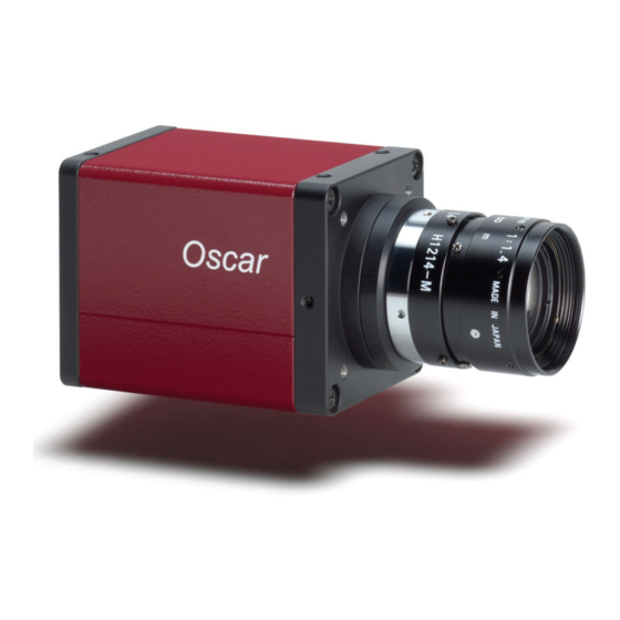
OSCAR cameras OSCAR cameras Oscar With Oscar cameras, entry into the world of digital image processing is sim- pler and more cost-effective than ever before. High image quality With the new Oscar, Allied Vision Technologies presents a whole series of attractive digital camera models of the FireWire™... -
Page 18: Declarations Of Conformity
Declarations of conformity Declarations of conformity Allied Vision Technologies declares under its sole responsibility that the fol- lowing products Category Name Model Name Digital camera (IEEE 1394) OSCAR F-320C OSCAR F-510C OSCAR F-810C Table 3: Model names to which this declaration relates is in conformity with the following stan- dard(s) or other normative document(s): •... -
Page 19: Filter And Lenses
Filter and lenses Filter and lenses IR cut filter: spectral transmission The following illustration shows the spectral transmission of the IR cut filter: Figure 1: Spectral transmission of Jenofilt 217 OSCAR Technical Manual V2.4.0... -
Page 20: Camera Lenses
Filter and lenses Camera lenses AVT offers different lenses from a variety of manufacturers. The following table lists selected image formats in width x height depending on camera type, distance and the focal length of the lens. Note Due to its extreme high resolution, OSCAR cameras place high demands on the modulation transfer function (MTF) of the lens. -
Page 21: Specifications
Specifications Specifications Note Oscar cameras are always equipped with color sensors. Note For information on bit/pixel and byte/pixel for each color mode see Table 61: ByteDepth on page 142. Oscar F-320C Feature Specification Image device Type 1/1.8 (diag. 8.93 mm) frame readout SONY CCD ICX-262AQ with HAD microlens Chip size 8.10 mm x 6.64 mm... - Page 22 Specifications Feature Specification External trigger shutter Trigger Mode_0, Trigger_Mode_1 (progressive scan, Format_7 Mode_0); advanced feature: Trigger_Mode_15 (bulk); image transfer by command; trigger delay Internal FIFO memory 32 MByte, optional up to 256 MByte Look-up tables One, user programmable (12 bit 8/12 bit);...
-
Page 23: Oscar F-510C
Specifications Oscar F-510C Feature Specification Image device Type 2/3 (diag. 11 mm) frame readout SONY CCD ICX-282AQ with HAD microlens Chip size 9.74 mm x 7.96 mm Cell Size 3.4 µm x 3.4 µm Picture size (max.) 2588 x 1958 pixels (Format_7 Mode_0) Lens mount C-Mount: 17.526 mm (in air);... - Page 24 Specifications Feature Specification Mass <170 g (without lens and tripod) Operating temperature +5 ... +45 °Celsius Storage temperature -10 ... +60 °Celsius Regulations CE, FCC Class B, RoHS (2002/95/EC) Standard accessories IR cut filter Optional accessories Protection glass, locking IEEE 1394 cable On request Host adapter card, angled head Software packages...
-
Page 25: Oscar F-810C
Specifications Oscar F-810C Feature Specification Image device Type 2/3 (diag. 11.07 mm) frame readout SONY CCD ICX-456AQ with HAD microlens Chip size 9.79 mm x 7.93 mm Cell size 2.7 µm x 2.7 µm Picture size (max.) 3272 x 2469 pixels (Format_7 Mode_0) Lens mount C-Mount: 17.526 mm (in air);... - Page 26 Specifications Feature Specification Mass <170 g (without lens and tripod) Operating temperature +5 ... +45 °Celsius Storage temperature -10 ... +60 °Celsius Regulations CE, FCC Class B, RoHS (2002/95/EC) Standard accessories IR cut filter Optional accessories Protection glass, locking IEEE 1394 cable On request Host adapter card, angled head Software packages...
-
Page 27: Spectral Sensitivity
Specifications Spectral sensitivity Figure 2: Spectral sensitivity of Oscar F-320C without cut filter and optics Figure 3: Spectral sensitivity of Oscar F-510C without cut filter and optics OSCAR Technical Manual V2.4.0... - Page 28 Specifications Figure 4: Spectral sensitivity of Oscar F-810C without cut filter and optics OSCAR Technical Manual V2.4.0...
-
Page 29: Camera Dimensions
Camera dimensions Camera dimensions Note For information on sensor position accuracy: (sensor shift x/y, optical back focal length z and sensor rota- tion α) see Chapter Sensor position accuracy of AVT cameras on page 203. Oscar standard housing ☺ Body size: 72.5 mm x 44 mm x 44 mm (L x W x H) Mass: 170 g (without lens) Figure 5: Camera dimensions OSCAR Technical Manual V2.4.0... -
Page 30: Oscar W90
Camera dimensions Oscar W90 This version has the sensor tilted by 90 degrees clockwise, so that it views upwards. Note An additional specification is required for the rotation of the sensor. Figure 6: Oscar W90 OSCAR Technical Manual V2.4.0... -
Page 31: Oscar W270
Camera dimensions Oscar W270 This version has the sensor tilted by 270 degrees clockwise, so that it views downwards. Please note that an additional specification is required for the rotation of the sensor. Figure 7: Oscar W270 OSCAR Technical Manual V2.4.0... -
Page 32: Tripod Adapter
Camera dimensions Tripod adapter Figure 8: Tripod dimensions OSCAR Technical Manual V2.4.0... -
Page 33: Cross Section: C-Mount (Standard Filter)
Camera dimensions Cross section: C-Mount (standard filter) All Oscar cameras are equipped with standard filter. Figure 9: Oscar C-Mount dimensions (standard filter) OSCAR Technical Manual V2.4.0... -
Page 34: Adjustment Of C-Mount
Camera dimensions Adjustment of C-Mount Oscar cameras allow the precise adjustment of the back focus of the C-Mount by means of a back focus ring which is threaded into the C-Mount and held by two screws on either side of the camera. The mechanical adjustment of the imaging device is important in order to achieve a perfect alignment with the focal point of the lens. -
Page 35: Camera Interfaces
Camera interfaces Camera interfaces This chapter gives you detailed information on status LEDs, inputs and out- puts, trigger features and transmission of data packets. Note For a detailed description of the camera interfaces (FireWire, I/O connector), ordering numbers and operat- ing instructions see the Hardware Installation Guide, Chapter Camera interfaces. -
Page 36: Camera I/O Pin Assignment
Camera interfaces Camera I/O pin assignment Pin Signal Direction Level Description External GND GND for RS232 and External ground for RS232 ext. power and external power External Power +8 ... +36 V DC Power supply Camera In 1 (high) = 2 V...U Camera Input 1 inVCC (GPIn1) -
Page 37: Status Leds
Camera interfaces Status LEDs Status LEDs Figure 13: Position of Status LEDs On LED The green power LED indicates that the camera is being supplied with suffi- cient voltage and is ready for operation. Status LED (yellow) The following states are displayed via the LED: State Description Asynchronous and isochronous data transmission... - Page 38 Camera interfaces Blink codes are used to signal warnings or error states: Warning DCAM MISC FPGA Stack Class S1 1 blink 2 blinks 3 blinks 4 blinks 5 blinks Error codes S2 FPGA boot error 1-5 blinks Stack setup 1 blink Stack start 2 blinks No FLASH object...
-
Page 39: Control And Video Data Signals
Camera interfaces Control and video data signals The inputs and outputs of the camera can be configured by software. The dif- ferent modes are described below. Inputs Note For a general description of the inputs and warnings see the Hardware Installation Guide, Chapter OSCAR input descrip- tion. -
Page 40: Input/Output Pin Control
Camera interfaces Input/output pin control All input and output signals running over the camera I/O connector are con- trolled by an advanced feature register. Register Name Field Description 0xF1000300 IO_INP_CTRL1 Presence_Inq Indicates presence of this feature (read only) [1..6] Reserved Polarity 0: low active 1: high active... -
Page 41: Io_Inp_Ctrl 1-2
Camera interfaces IO_INP_CTRL 1-2 The Polarity flag determines whether the input is low active (0) or high active (1). The input mode can be seen in the following table. The PinState flag is used to query the current status of the input. •... -
Page 42: Trigger Delay
Camera interfaces Trigger delay Oscar cameras feature various ways to delay image capture based on an exter- nal trigger. With IIDC V1.31 there is a standard CSR at register F0F00534/834h to control a delay up to FFFh x time base value. The following table explains the inquiry register and the meaning of the var- ious bits. - Page 43 Camera interfaces Register Name Field Description 0xF0F00834 TRIGGER_DELAY Presence_Inq Presence of this feature: 0: N/A 1: Available Abs_Control Absolute value control O: Control with value in the value field 1: Control with value in the absolute value CSR If this bit= 1 the value in the value field has to be ignored.
-
Page 44: Outputs
Camera interfaces Note • Switching trigger delay to ON also switches external Trigger_Mode_0 to ON. • This feature works with external Trigger_Mode_0 only. Outputs Note For a general description of the outputs and warnings see the Hardware Installation Guide, Chapter OSCAR output description. - Page 45 Camera interfaces Output mode selectable Polarity via software selectable via software Operation state IntEna read FVal Opto- Busy Output signal Operation state Coupler read Figure 15: Output block diagram OSCAR Technical Manual V2.4.0...
-
Page 46: Io_Outp_Ctrl 1-2
Camera interfaces IO_OUTP_CTRL 1-2 The outputs (Output mode, Polarity) are controlled via two advanced feature registers. The Polarity flag determines whether the output is active low (0) or active high (1). The output mode can be viewed in the table below. The current status of the output can be queried and set via the PinState flag. -
Page 47: Output Modes
Camera interfaces Output modes Mode Default 0x00 0x01 Output state follows PinState bit Using this mode, the Polarity bit has to be set to 0 (not inverted). This is necessary for an error free display of the output status. 0x02 Integration enable Output 1 0x03... - Page 48 Camera interfaces Figure 16: Output impulse diagram Note The signals can be inverted. Note • Note that trigger delay in fact delays the image cap- ture whereas the IntEna_Delay only delays the leading edge of the IntEna output signal but does not delay the image capture.
-
Page 49: Pixel Data
Camera interfaces Pixel data Pixel data are transmitted as isochronous data packets in accordance with the 1394 interface described in IIDC V1.3. The first packet of a frame is iden- tified by the 1 in the sync bit (sy) of the packet header. sync bit 8-15 16-23... - Page 50 Camera interfaces The following table provides a description of the video data format for the different modes. (Source: IIDC V1.3) Figure 17: YUV 4:2:2 and YUV 4:1:1 format: Source: IIDC V1.3 Figure 18: Y8 and Y16 format: Source: IIDC V1.3 OSCAR Technical Manual V2.4.0...
- Page 51 Camera interfaces Figure 19: Data structure: Source: IIDC V1.3 OSCAR Technical Manual V2.4.0...
-
Page 52: Description Of The Data Path
Description of the data path Description of the data path Block diagram of the cameras The following diagram illustrates the data flow and the bit resolution of image data after being read from the CCD sensor chip in the camera. The indi- vidual blocks are described in more detail in the following paragraphs. -
Page 53: Black And White Output Interpolation Modes
Description of the data path Black and white output interpolation modes Various black and white output interpolation modes have been implemented in the data path to ensure high quality black and white image output. The cameras are able to output: •... -
Page 54: Oscar F-320C: Icx-262Aq Readout Scheme
Description of the data path Oscar F-320C: ICX-262AQ readout scheme The screenshot below, taken from the Oscar F-320C sensor's data sheet, shows the ICX-262AQ readout scheme. Frame readout mode reads out red and green color pixels in the first field, followed by the green and blue pixels in the second field. -
Page 55: Oscar F-510C: Icx-282Aq Readout Scheme
Description of the data path 2. High frame rate readout mode Output is performed at 30 frames per second by reading out 2 pixels for every 12 vertical pixels. The number of output lines is 258 lines. This readout mode emphasizes processing speed over vertical resolu- tion. -
Page 56: Oscar F-810C: Icx-456Aq Readout Scheme
Description of the data path Oscar F-810C: ICX-456AQ readout scheme Oscar F-810C uses the ICX-456AQ sensor with three field readout mode. Every field skips two lines during read out, so all primary colors of the BAYER mosaic are read out in every field. Progressive scan mode reads out 2 out of 6 lines. -
Page 57: Frame Readout Implications
Description of the data path Frame readout implications Frame readout has implications when shooting moving or stationary objects. To compensate for this condition, two different shutter modes have been introduced. The so-called split shutter opens and closes the shutter per field. This mode is suitable for shooting stationary objects only. - Page 58 Description of the data path Exposure (Flash) Shutter first field Output first field to camera buffer Shutter second field Output second field to camera buffer Figure 25: Joint shutter The following pre-requisites are necessary to handle moving image acquisi- tion in joint shutter mode: •...
-
Page 59: White Balance
Description of the data path White balance Oscar cameras have both manual and automatic white balance. White balance is applied so that non-colored image parts are displayed non- colored. White balance does not use the so called PxGA® (Pixel Gain Amplifier) of the analog front end (AFE) but a digital representation in the FPGA in order to modify the gain of the two channels with lower output by +9.5 dB (in 512 steps) relative to the channel with highest output. - Page 60 Description of the data path From the user's point of view, the white balance settings are made in register 80Ch of IIDC V1.3. This register is described in more detail below. Register Name Field Description 0xF0F0080C WHITE_BALANCE Presence_Inq [0] Presence of this feature: 0: N/A;...
-
Page 61: One-Push Automatic White Balance
Description of the data path Figure 27: U/V slider range One-push automatic white balance Note Configuration To configure this feature in control and status register (CSR): See Chapter White balance register on page 60. To activate one-push automatic white balance: Set one-push bit in the WHITE_BALANCE register. - Page 62 Description of the data path If the image capture is active (e.g. IsoEnable set in register 614h), the frames used by the camera for white balance are also output on the 1394 bus. Any previously active image capture is restarted after the completion of white balance.
-
Page 63: Automatic White Balance
Description of the data path Automatic white balance The auto white balance feature continuously optimizes the color characteris- tics of the image. As a reference, it uses a grid of at least 300 samples equally spread over the area of interest or a fraction of it. Note Configuration To set position and size of the control area... -
Page 64: Manual Gain
Description of the data path The algorithm bases on the assumption that the R-G-B component sums of the samples are equal, i.e., it assumes that the mean of the sampled grid pix- els is to be monochrome. Visualization of the AUTOFNC_AOI is carried out with the help of the graphics overlay function of the camera (see Chapter Block diagram of the cameras page 52). -
Page 65: Auto Gain
Description of the data path Auto gain In combination with auto white balance, all Oscar cameras are equipped with auto gain feature. When enabled auto gain adjusts the gain within the default gain limits or within the limits set in advanced register F1000370h in order to reach the brightness set in auto exposure register as reference. - Page 66 Description of the data path Register Name Field Description 0xF0F00804 AUTO_EXPOSURE Presence_Inq Presence of this feature: 0: N/A 1: Available Abs_Control Absolute value control O: Control with value in the value field 1: Control with value in the absolute value CSR If this bit=1, the value in the value field has to be ignored.
-
Page 67: Brightness (Black Level Or Offset)
Description of the data path Note • Values can only be changed within the limits of gain CSR. • Changes in auto exposure register only have an effect when auto gain is active. • Auto exposure limits are 50..205. (SmartView Ctrl1 tab: Target grey level) Brightness (black level or offset) It is possible to set the black level in the camera within the following ranges:... - Page 68 Description of the data path The IIDC brightness register at offset 800h is used for this purpose. The following table shows the BRIGHTNESS register. Register Name Field Description 0xF0F00800 BRIGHTNESS Presence_Inq Presence of this feature: 0: N/A 1: Available Abs_Control Absolute value control O: Control with value in the value field 1: Control with value in the absolute...
-
Page 69: Auto Shutter
Description of the data path Auto shutter In combination with auto white balance, Oscar cameras are equipped with an auto shutter feature. When enabled, the auto shutter adjusts the shutter within the default shutter limits or within those set in advanced register F1000360h in order to reach the reference brightness set in auto exposure register. - Page 70 Description of the data path To configure this feature in control and status register (CSR): Register Name Field Description 0xF0F0081C SHUTTER Presence_Inq Presence of this feature: 0: N/A 1: Available Abs_Control Absolute value control O: Control with value in the value field 1: Control with value in the absolute value CSR If this bit=1, the value in the value field has to be ignored.
-
Page 71: Look-Up Table (Lut) And Gamma Function
Description of the data path Look-up table (LUT) and gamma function The AVT Oscar camera provides one user-defined look-up table (LUT). The use of this LUT allows any function (in the form Output = F(Input)) to be stored in the camera's RAM and to be applied on the individual pixels of an image at run-time. - Page 72 Description of the data path Note • The input value is the most significant 12-bit value from the digitizer. The gamma LUT outputs the most significant 8 bit as shown above. • As gamma correction is also implemented via the LUT, it is not possible to use a different LUT when gamma correction is enabled.
-
Page 73: Loading An Lut Into The Camera
Description of the data path Loading an LUT into the camera Loading the LUT is carried out through the data exchange buffer called GPDATA_BUFFER. As this buffer can hold a maximum of 2 kByte, and a com- plete LUT at 4026 x 8 bit is 4 kByte, programming can’t take place in a one block write step because the size of an LUT is larger than GPDATA_BUFFER. -
Page 74: Shading Correction
Description of the data path Shading correction Shading correction is used to compensate for non-homogeneities caused by lighting or optical characteristics within specified ranges. To correct a frame, a multiplier from 1...2 is calculated for each pixel in 1/ 256 steps. This allows for shading to be compensated by up to 50%. Besides generating shading data off-line and downloading it to the camera, the camera allows correction data to be generated automatically in the cam- era itself. -
Page 75: Automatic Generation Of Correction Data
Description of the data path Automatic generation of correction data Requirements Shading correction compensates for non-homogeneities by giving all pixels the same gray value as the brightest pixel. This means that only the back- ground must be visible and the brightest pixel has a gray value of less than 255 when automatic generation of shading data is started. - Page 76 Description of the data path Note Configuration To configure this feature in an advanced register: See Table 90: Advanced register: Shading on page 188. Note The SHDG_CTRL register should not be queried at very short intervals. This is because each query delays the generation of the shading image.
- Page 77 Description of the data path Figure 34: Generation of shading image After the lens has been focused again, the image below will be seen, but now with a considerably more uniform gradient. This is also made apparent in the graph on the right. OSCAR Technical Manual V2.4.0...
- Page 78 Description of the data path Figure 35: Example of shaded image The shading reference image can be output for permanent storage purposes on a host system. It can be further uploaded into the camera, so that the shading procedure must not be repeated after power down of the camera. OSCAR Technical Manual V2.4.0...
-
Page 79: What Is The Real Size Of The Shading Image (Maximagesize)
Description of the data path What is the real size of the shading image (MaxImageSize)? The register 0xF1000258 SHDG_INFO (MaxImageSize) delivers the sensor size but not the size of the shading image buffer. Therefore: If you use this reported (but wrong) MaxImageSize then: •... - Page 80 Description of the data path Camera model N: number of fields BufferSize per frame Oscar F-320C 620000h Oscar F-510C A00000h Oscar F-810C FC0000h Table 27: Number of fields and BufferSize For uploading/downloading a shading image the last Gap n can be ignored. The size of a field is calculated from the MaxImageSize which is theoretically camera dependent (MaxImageSize <...
-
Page 81: Loading A Shading Image Out Of The Camera
Description of the data path Loading a shading image out of the camera GPDATA_BUFFER is used to load a shading image out of the camera. Due to the size of a shading image being larger than GPDATA_BUFFER, output must be handled in several steps: Query limits from register: SHDG_INFO and... -
Page 82: Loading A Shading Image Into The Camera
Description of the data path Loading a shading image into the camera GPDATA_BUFFER is used to load a shading image into the camera. Because the size of a shading image is larger than GPDATA_BUFFER, input must be handled in several steps: It is recommended that block writes are used to write a block of n bytes with one command into the GPDATA_BUFFER. -
Page 83: Horizontal Mirror Function
Description of the data path Horizontal mirror function All Oscar cameras are equipped with an electronic mirror function, which mirrors pixels from the left side of the image to the right side and vice versa. The mirror is centered to the current FOV center and can be combined with all image manipulation functions, like binning, shading and DSNU. -
Page 84: Binning (Only Oscar F-510C)
Description of the data path Binning (only Oscar F-510C) 2 x Binning Definition Binning is the process of combining neighboring pixels while being read out from the CCD chip. Note Only Oscar F-510C has the binning feature. Binning is used primarily for 3 reasons: •... -
Page 85: Vertical Binning
Description of the data path Vertical binning Vertical binning increases the light sensitivity of the camera by a factor of two by adding together the values of two adjoining vertical pixels output as a single pixel. At the same time this normally improves signal-to-noise sep- aration by about 3 dB. -
Page 86: Horizontal Binning
Description of the data path Horizontal binning Definition In horizontal binning adjacent horizontal pixels in a line are combined in pairs. This means that in horizontal binning the light sensitivity of the camera is also increased by a factor of two (6 dB). Signal-to-noise separation improves by approx. -
Page 87: X Full Binning
Description of the data path 2 x full binning If horizontal and vertical binning are combined, every 4 pixels are consoli- dated into a single pixel. At first two horizontal pixels are put together and then combined vertically. Light sensitivity This increases light sensitivity by a total of a factor of 4 and at the same time signal-to-noise separation is improved by about 6 dB. -
Page 88: Sub-Sampling
Description of the data path Sub-sampling What is sub-sampling? Definition Sub-sampling is the process of skipping neighboring pixels (with the same color) while being read out from the CCD chip. Which Oscar models have sub-sampling? All Oscar models have this feature. Description of sub-sampling Sub-sampling is used primarily for the following reasons: •... -
Page 89: High Snr Mode (High Signal Noise Ratio)
Description of the data path 2 out of 4 H+V sub-sampling Figure 42: 2 out of 4 H+V sub-sampling (color) Note Changing sub-sampling modes involves the generation of new shading reference images due to a change in the image size. High SNR mode (High Signal Noise Ratio) To configure this feature in an advanced register: See Table 101: Advanced... -
Page 90: Sharpness
Description of the data path Sharpness All Oscar models are equipped with a two-step sharpness control, applying a discreet horizontal high pass in the green channel as shown in the next three line profiles. Figure 43: Sharpness: left: 0, middle: 1, right: 2 Note Configuration To configure this feature in feature control register: See... -
Page 91: Color Interpolation (Bayer Demosaicing)
Description of the data path RAW mode is accessible via Color_Mode Mono8, RAW8 and via Format_7. Note If the PC does not perform BAYER to RGB post-processing the b/w image will be superimposed with a checkerboard pattern. Color interpolation (BAYER demosaicing) In color interpolation, a red, green or blue value is determined for each pixel. -
Page 92: Color Correction
Description of the data path Color correction Why color correction? The spectral response of a CCD is different of those of an output device or the human eye. This is the reason for the fact that perfect color reproduction is not possible. In each Oscar camera there is a factory setting for the color correction coefficients, see Chapter GretagMacbeth ColorChecker on page 92. -
Page 93: Color Conversion (Rgb Yuv)
Description of the data path Color correction can also be switched off in YUV mode with the help of the following register: Register Name Description 0xF10003A0 COLOR_CORR Write: 02000000h to switch color correction OFF Write: 00000000h to switch color correction ON (default) Table 28: Color correction switch off in YUV mode Color conversion (RGB YUV) - Page 94 Description of the data path This means a setting of zero changes the image to black and white and a set- ting of 511 doubles the color intensity compared to the nominal one at 256. Note Configuration To configure this feature in feature control register: See Table 77: Feature control register on page 169.
-
Page 95: Serial Interface
Description of the data path Serial interface All Oscar cameras are equipped with the SIO (serial input/output) feature as described in IIDC V1.31. This means that the Oscar's serial interface which is used for firmware upgrades can also be used as a general RS232 interface. Data written to a specific address in the IEEE 1394 address range will be sent through the serial interface. - Page 96 Description of the data path To configure this feature in access control register (CSR): Offset Name Field Description 000h SERIAL_MODE_REG Baud_Rate [0..7] Baud rate setting WR: Set baud rate RD: Read baud rate 0: 300 bps 1: 600 bps 2: 1200 bps 3: 2400 bps 4: 4800 bps 5: 9600 bps...
- Page 97 Description of the data path Offset Name Field Description 0004h SERIAL_CONTROL_REG RE Receive enable RD: Current status 0: Disable 1: Enable Transmit enable RD: Current status 0: disable 1: Enable [2..7] Reserved SERIAL_STATUS_REG TDRD Transmit data buffer ready Read only 0: not ready 1: ready Reserved...
- Page 98 Description of the data path Offset Name Field Description 008h RECEIVE_BUFFER_ RBUF_ST [0..7] SIO receive buffer status STATUS_CONTRL RD: Number of bytes pending in receive buffer WR: Ignored RBUF_CNT [8..15] SIO receive buffer control RD: Number of bytes to be read from the receive FIFO WR: Number of bytes left for readout from the receive FIFO...
- Page 99 Description of the data path To read data: 1. Query RDRD flag (buffer ready?) and write the number of bytes the host wants to read to RBUF_CNT. 2. Read the number of bytes pending in the receive buffer RBUF_ST (more data in the buffer than the host wanted to read?) and the number of bytes left for reading from the receive FIFO in RBUF_CNT (more data the host wanted to read than were in the buffer?).
-
Page 100: Controlling Image Capture
Controlling image capture Controlling image capture Shutter modes The cameras support the SHUTTER_MODES specified in IIDC V1.3. For all mod- els this shutter is a global (field) shutter; meaning that all pixels (in the same field) are exposed to the light at the same moment and for the same time span. -
Page 101: Level Mode (Trigger_Mode_1)
Controlling image capture Level mode (Trigger_Mode_1) Trigger_Mode_1 sets the shutter time in the progressive modes according to the active low time of the pulse applied (or active high time in the case of an inverting input). External Trigger input, as applied at input pin, trigger falling edge External Trigger input, after inverting opto coupler Shutter register value External Trigger input, as applied at input pin... -
Page 102: Bulk Trigger (Trigger_Mode_15)
Controlling image capture Bulk trigger (Trigger_Mode_15) Trigger_Mode_15 is a bulk trigger, combining one external trigger event with continuous or one-shot or multi-shot internal trigger. It is an extension of the IIDC trigger modes. One external trigger event can be used to trigger a multitude of internal image intakes. This is especially useful for: •... - Page 103 Controlling image capture The functionality is controlled via bit [6] and bitgroup [12-15] of the IIDC register: Register Name Field Description 0xF0F00830 TRIGGER_MODE Presence_Inq Presence of this feature: 0: N/A 1: Available Abs_Control Absolute value control O: Control with value in the Value field 1: Control with value in the Absolute value If this bit = 1 the value in the value field has to be ignored.
- Page 104 Controlling image capture The screenshots below illustrate the use of Trigger_Mode_15 on a register level: • The first line switches continuous mode off, leaving viewer in listen mode. • The second line prepares 830h register for external trigger and Mode_15. Left = continuous Middle = one-shot Right = multi-shot...
-
Page 105: Trigger Delay
Controlling image capture Trigger delay As already mentioned earlier, the cameras feature various ways to delay image capture based on external trigger. With IIDC V1.31 there is a standard CSR at Register F0F00534/834h to control a delay up to FFFh x time base value. The following table explains the inquiry register and the meaning of the var- ious bits. -
Page 106: Trigger Delay Advanced Register
Controlling image capture Name Field Description 0xF0F00834 TRIGGER_DELAY Presence_Inq Presence of this feature: 0: N/A 1: Available Abs_Control Absolute value control O: Control with value in the Value field 1: Control with value in the Absolute value CSR If this bit = 1, the value in the Value field has to be ignored [2..5] Reserved... - Page 107 Controlling image capture The advanced register allows the start of the integration to be delayed by max. 2 µs, which is max. 2.1 s after a trigger edge was detected. Note • Switching trigger delay to ON also switches external Trigger_Mode_0 to ON.
-
Page 108: Shutter Modes
Controlling image capture Shutter modes Due to the frame readout (interlaced) modes of the sensors, two different shutter modes exist for the maximum resolution formats accessible via the mode register in Format_7. The conversion from interlaced to progressive takes place in the camera's internal memory. - Page 109 Controlling image capture Note • Combining split shutter with one-shot operation, it can also be seen from the above figure that the frame rate in one-shot mode is lower than that in continuous mode. This is a result of the additional delay of one or two (Oscar F-810C) fields before the progressive output of the camera can start.
-
Page 110: Joint Shutter
Controlling image capture Joint shutter Use Format_7 Mode_0 when a strobe light flashes moving objects. The exposure for the two (three: F-810C) fields starts concurrently so that the strobe freezes odd and even lines at the same time. Field one is read out first, field two (and three) are read out after field one. -
Page 111: Exposure Time (Shutter) And Offset
Controlling image capture Exposure time (shutter) and offset The exposure (shutter) time for continuous mode and Trigger_Mode_0 is based on the following formula: Shutter register value x time base + offset The register value is the value set in the corresponding IIDC register (SHUTTER [81Ch]). -
Page 112: Extended Shutter
Controlling image capture Extended shutter The exposure time for long-term integration of up to 67 seconds can be extended via the advanced register: EXTENDED_SHUTTER Register Name Field Description 0xF100020C EXTD_SHUTTER Presence_Inq Indicates presence of this feature (read only) [1.. 5] Reserved ExpTime [6..31] Exposure time in µs... -
Page 113: One-Shot
Controlling image capture One-shot Oscar cameras can record an image by setting the one-shot bit in the 61Ch register. This bit is automatically cleared after the image is captured. If the camera is placed in ISO_Enable mode (see Chapter ISO_Enable / free-run page 115), this flag is ignored. -
Page 114: End Of Exposure To First Packet On The Bus
Controlling image capture Microcontroller sync is an internal signal. It is generated by the microcon- troller to initiate a trigger. This can either be a direct trigger or a release for ExSync, if the camera is externally triggered. End of exposure to first packet on the bus After the exposure, the CCD sensor is read out;... -
Page 115: Multi-Shot
Controlling image capture Multi-shot Setting multi-shot and entering a quantity of images in Count_Number in the 61Ch register enables the camera to record a specified number of images. The number is indicated in bits 16 to 31. If the camera is put into ISO_Enable mode (see Chapter ISO_Enable / free-run on page 115), this flag... -
Page 116: Jitter At Start Of Exposure
Controlling image capture The following screenshot shows an example of broadcast commands sent with the Firedemo example of FirePackage (version 1V51 or newer): Figure 53: Broadcast one-shot • Line 1 shows the broadcast command, which stops all cameras con- nected to the same IEEE 1394 bus. It is generated by holding the Shift key down while clicking on Write. -
Page 117: Frame Memory And Deferred Image Transport
Controlling image capture In this case the camera can resynchronize the horizontal clock to the new trigger event, leaving only a very short uncertainty time of the master clock period. Model Camera idle Camera busy ± 3.35 µs ± 98 µs Oscar F-320C ±... -
Page 118: Holdimg Mode
Controlling image capture Image transfer is controlled from the host computer by addressing individual cameras and reading out the desired number of images. Functionality is con- trolled by the following register: Register Name Field Description 0xF1000260 DEFERRED_TRANS Presence_Inq Indicates presence of this feature (read only) [1..4] Reserved... -
Page 119: Fastcapture
Controlling image capture The following screenshot shows the sequence of commands needed to work with deferred mode........Stop continuous mode of camera .........Check pres. of deferred mode and FiFo size (Dh= 13 fr.) .........Switch deferred mode on .........Do first One_shot .........Do second One_shot .........Check that two images are in FiFo .........Read out the first image of FiFo... -
Page 120: Video Formats, Modes And Bandwidth
Video formats, modes and bandwidth Video formats, modes and bandwidth The different Oscar models support different video formats, modes and frame rates. These formats and modes are standardized in the IIDC (formerly DCAM) spec- ification. Resolutions in Format_0, Format_1 and Format_2, which are smaller than the generic sensor resolution, are generated symmetrically from the center of the sensor and without binning. -
Page 121: Video Formats: Oscar F-320C
Video formats, modes and bandwidth Video formats: Oscar F-320C Format Mode Resolution Color mode 60 3.75 1.875 160 x 120 YUV444 320 x 240 YUV422 640 x 480 YUV411 640 x 480 YUV422 640 x 480 RGB8 640 x 480 MONO8 640 x 480 MONO16... - Page 122 Video formats, modes and bandwidth Format Mode Resolution Color mode Frame rate / fps Description Mono8 39.31 YUV411 39.31 YUV422 39.31 progressive preview mode RGB8 344 x 254 39.51 sub-sampling Raw8 39.31 Raw16 39.31 Y8red, Y8green, Y8blue 39.31 Table 44: Video Format_7 formats Oscar F-320C [1] Camera outputs RAW image which needs to be converted outside of camera.
-
Page 123: Video Formats: Oscar F-510C
Video formats, modes and bandwidth Video formats: Oscar F-510C Format Mode Resolution Color mode 60 3.75 1.875 800 x 600 YUV422 800 x 600 RGB8 800 x 600 MONO8 1024 x 768 YUV422 1024 x 768 RGB8 1024 x 768 MONO8 800 x 600 MONO16 1024 x 768 MONO16 1280 x 960... - Page 124 Video formats, modes and bandwidth Format Mode Resolution Color mode Frame rate / fps Description Mono8 3.80 YUV411 3.80 YUV422 3.23 frame readout 2588 x 1958 RGB8 2.15 joint shutter Raw8 3.80 Raw16 3.23 Y8red, Y8green, Y8blue 3.80 Mono8 3.80 YUV411 3.80 YUV422...
- Page 125 Video formats, modes and bandwidth Format Mode Resolution Color mode Frame rate / fps Description Mono8 3.87 YUV411 3.87 YUV422 3.25 progressive scan 2576 x 1958 RGB8 2.16 V-line-doubling Raw8 3.87 Raw16 3.25 Y8red, Y8green, Y8blue 3.87 Mono8 3.79 YUV411 3.80 interlaced, YUV422...
- Page 126 Video formats, modes and bandwidth [1] Camera outputs RAW image which needs to be converted outside of camera. [2] Camera outputs interpolated B/W image using luma interpolation formula. [3] Camera outputs interpolated B/W image using one of the R-G-B color planes. [4] Only achievable with shutter settings that don't exceed 1/framerate.
-
Page 127: Video Formats: Oscar F-810C
Video formats, modes and bandwidth Video formats: Oscar F-810C Format Mode Resolution Color mode 60 3.75 1.875 800 x 600 YUV422 800 x 600 RGB8 800 x 600 MONO8 1024 x 768 YUV422 1024 x 768 RGB8 1024 x 768 MONO8 800 x 600 MONO16 1024 x 768 MONO16 Table 48: Fixed video formats... - Page 128 Video formats, modes and bandwidth Format Mode Resolution Color mode Frame rate / fps Description Mono8 8.86 YUV411 8.88 YUV422 8.88 progressive scan 1088 x 822 RGB8 8.88 sub-sampling Raw8 8.86 Raw16 8.88 Y8red, Y8green, Y8blue 8.86 Table 49: Format_7 video formats Oscar F-810C [1] Camera outputs RAW image which needs to be converted outside of camera.
-
Page 129: Area Of Interest (Aoi)
Video formats, modes and bandwidth Area of interest (AOI) pixels per line that the recorded image may have. However, often only a certain section of the entire image is of interest. The amount of data to be transferred can be decreased by limiting the image to a section when reading it out from the camera. - Page 130 Video formats, modes and bandwidth Figure 55: Area of Interest (AOI) Note • The left position + width and the upper position + height may not exceed the maximum resolution of the sensor. The increments may vary from model and mode. •...
-
Page 131: Frame Rates
Video formats, modes and bandwidth In addition to the Area of Interest, some other parameters have an effect on the maximum frame rate: • The time for reading the image from the sensor and transporting it into the FRAME_BUFFER • The time for transferring the image over the FireWire™... - Page 132 Video formats, modes and bandwidth Format Mode Resolution 3.75 160 x 120 YUV (4:4:4) 1/2H 1/4H 1/8H 24 bit/pixel 320 x 240 YUV (4:2:2) 1/2H 1/4H 1/8H 320p 160p 16 bit/pixel 160q 640 x 480 YUV (4:1:1) 1/2H 1/4H 1280p 640p 320p 160p...
- Page 133 Video formats, modes and bandwidth Format Mode Resolution Color mode 60 3.75 1.875 800 x 600 YUV (4:2:2) 5/2H 5/4H 5/8H 6/16H 2000p 1000p 500p 250p 16 bit/pixel 1000q 500q 250q 125q 800 x 600 5/4H 5/8H 1000p 500p 24 bit/pixel 750q 375q 800 x 600...
- Page 134 Video formats, modes and bandwidth Format Mode Resolution Color Mode 60 3.75 1.875 1280 x 960 YUV (4:2:2) 1/2H 1/4H 1280p 640p 320p 16 bit/pixel 640q 320q 160q 1280 x 960 1/2H 1/4H 1280p 640p 320p 24 bit/pixel 960q 480q 240q 1280 x 960 Y (MONO8)
-
Page 135: Frame Rates Format_7
Video formats, modes and bandwidth The frame rates in video modes 0 to 2 are specified and set fixed by IIDC V1.3. Frame rates Format_7 In video Format_7 frame rates are no longer fixed but can be varied dynam- ically by the parameters described below. Note •... -
Page 136: Oscar F-320C: Aoi Frame Rates
Video formats, modes and bandwidth Oscar F-320C: AOI frame rates Frame rates differ for the progressive scan mode and the field read out (or interlaced) mode. Oscar F-320C: progressive scan mode For progressive scan mode (i.e. fixed formats and Format_7, Mode_2), the following formula applies: ---------------------------------------------------------------------------------------------- - frame rate... -
Page 137: Oscar F-320C: Interlaced Mode
Video formats, modes and bandwidth Oscar F-320C: interlaced mode For interlaced mode, the following formula applies: ---------------------------------------------------------------------------------------------- - frame rate eTrans Dummy Dump Scan -------------------------------------------------------------------------------------------------------------------------------------------------------- frame rate ) x 6.8µs × – 580µs 1542 AOI_HEIGHT AOI_HEIGHT 98µs Formula 7: Frame rate calculation interlaced mode Oscar F-320C AOI height Frame rate / fps frame... -
Page 138: Oscar F-510C: Aoi Frame Rates
Video formats, modes and bandwidth Oscar F-510C: AOI frame rates Frame rates differ for the progressive scan mode and the field read out mode (or interlaced mode). Oscar F-510C: progressive scan mode For progressive scan mode (i.e. fixed formats and Format_7, Mode_2), the following formula applies: ---------------------------------------------------------------------------------------------- - frame rate... -
Page 139: Oscar F-510C: Interlaced Modes
Video formats, modes and bandwidth Oscar F-510C: interlaced modes For all interlaced modes (i.e. Format_7 Mode_0 and Mode_1), the following formula applies: -------------------------------------------------------------------------------------------------------------------------------------------------------------------- frame rate ⎛ ⎛ ⎞ ⎞ AOI_HEIGHT AOI_HEIGHT × × × ----------------------------- - ----------------------------- - – 233µs 4.9µs 134µs ⎝... -
Page 140: Oscar F-810C: Aoi Frame Rates
Video formats, modes and bandwidth Oscar F-810C: AOI frame rates Frame rates differ for the progressive scan mode and the field read out mode (interlaced mode). Oscar F-810C: progressive scan mode For progressive scan mode (i.e. fixed formats and Format_7, Mode_2), the following formula applies: ---------------------------------------------------------------------------------------------- - frame rate... -
Page 141: Oscar F-810C: Interlaced Modes
Video formats, modes and bandwidth Oscar F-810C: interlaced modes For all interlaced modes (i.e. Format_7 Mode_0 and Mode_1), the following formula applies: ------------------------------------------------------------------------------------------------------------------------------------------------------------------ - frame rate ⎛ ⎛ ⎞ ⎞ AOI_HEIGHT AOI_HEIGHT × × × ----------------------------- - ----------------------------- - – 291µs 16µs 128µs... -
Page 142: How Does Bandwidth Affect The Frame Rate
How does bandwidth affect the frame rate? How does bandwidth affect the frame rate? In some modes the IEEE 1394a bus limits the attainable frame rate. Accord- ing to the 1394a specification on isochronous transfer, the largest data pay- load size of 4096 bytes per 125 µs cycle is possible with bandwidth of 400 Mbit/s. -
Page 143: Example Formula For The Oscar F-810C Camera
How does bandwidth affect the frame rate? Example formula for the Oscar F-810C camera RGB8, 3272 x 2496 pixel, 2 fps desired × × × × > BYTE_PER_PACKET 3272 2469 125µs 6004 4096 4096 ⇒ ≈ ------------------------------------------------------------ framerate 1.35 × ×... - Page 144 How does bandwidth affect the frame rate? Oscar cameras have two test images. Figure 62: Test image 1 The second image is in colors: Figure 63: Test image 2 OSCAR Technical Manual V2.4.0...
-
Page 145: Configuration Of The Camera
Configuration of the camera Configuration of the camera All camera settings are made by writing specific values into the correspond- ing registers. This applies to: • values for general operating states such as video formats and modes, exposure times, etc. •... -
Page 146: Example
Configuration of the camera Every register is 32 bit (big endian) and implemented as follows (MSB = Most Significant Bit; LSB = Least Significant Bit): Far left Table 63: 32-bit register Example This requires, for example, that to enable ISO_Enabled mode (see Chapter ISO_Enable / free-run on page 115), (bit 0 in register 614h), the value 80000000 h must be written in the corresponding register. - Page 147 Configuration of the camera Figure 64: Configuration of the camera OSCAR Technical Manual V2.4.0...
-
Page 148: Configuration Rom
Configuration of the camera Configuration ROM The information in the configuration ROM is needed to identify the node, its capabilities and which drivers are required. The base address for the configuration ROM for all registers is FFFF F0000000h. Note If you want to use the DirectControl program to read or write to a register, enter the following value in the Address field: F0F00000h + Offset The configuration ROM is divided into... - Page 149 Configuration of the camera To compute the effective start address of the node unique ID leaf currAddr = node unique ID leaf address destAddr = address of directory entry addrOffset = value of directory entry destAddr = currAddr + (4 x addrOffset) = 420h + (4 x 000002h) = 428h Table 65: Computing effective start address...
- Page 150 Configuration of the camera Offset 8-15 16-23 24-31 444h ..unit_dep_info_length, CRC Unit dependent info 448h ..command_regs_base 44Ch ..vender_name_leaf 450h ..model_name_leaf Table 68: Configuration ROM And finally, the entry with key 40 (448h in this case) provides the offset for the camera control register: FFFF F0000000h + 3C0000h x 4 = FFFF F0F00000h The base address of the camera control register is thus: FFFF F0F00000h...
-
Page 151: Implemented Registers (Iidc V1.3)
Configuration of the camera Implemented registers (IIDC V1.3) The following tables show how standard registers from IIDC V1.3 are imple- mented in the camera. • Base address is F0F00000h • Differences and explanations can be found in the Description column. Camera initialize register Offset Name... -
Page 152: Inquiry Register For Video Mode
Configuration of the camera Inquiry register for video mode Offset Name Field Description Color mode 180h V_MODE_INQ Mode_0 160 x 120 YUV 4:4:4 Mode_1 320 x 240 YUV 4:2:2 (Format_0) Mode_2 640 x 480 YUV 4:1:1 Mode_3 640 x 480 YUV 4:2:2 Mode_4 640 x 480... -
Page 153: Inquiry Register For Video Frame Rate And Base Address
Configuration of the camera Offset Name Field Description Color mode 19Ch V_MODE_INQ Mode_0 Format_7 Mode_0 Mode_1 Format_7 Mode_1 (Format_7) Mode_2 Format_7 Mode_2 Mode_3 Format_7 Mode_3 Mode_4 Format_7 Mode_4 Mode_5 Format_7 Mode_5 Mode_6 Format_7 Mode_6 Mode_7 Format_7 Mode_7 [8..31] Reserved (zero) Table 71: Video mode inquiry register Inquiry register for video frame rate and base address... - Page 154 Configuration of the camera Offset Name Field Description 208h V_RATE_INQ FrameRate_0 1.875 fps FrameRate_1 3.75 fps (Format_0, Mode_2) FrameRate_2 7.5 fps FrameRate_3 15 fps FrameRate_4 30 fps FrameRate_5 60 fps FrameRate_6 120 fps (IIDC V1.31) FrameRate_7 240 fps (IIDC V1.31) [8..31] Reserved (zero) 20Ch...
- Page 155 Configuration of the camera Offset Name Field Description 214h V_RATE_INQ FrameRate_0 1.875 fps FrameRate_1 3.75 fps (Format_0, Mode_5) FrameRate_2 7.5 fps FrameRate_3 15 fps FrameRate_4 30 fps FrameRate_5 60 fps FrameRate_6 120 fps (IIDC V1.31) FrameRate_7 240 fps (IIDC V1.31) [8..31] Reserved (zero) 218h...
- Page 156 Configuration of the camera Offset Name Field Description 224h V_RATE_INQ FrameRate_0 Reserved FrameRate_1 Reserved (Format_1, Mode_1) FrameRate_2 7.5 fps FrameRate_3 15 fps FrameRate_4 30 fps FrameRate_5 60 fps FrameRate_6 120 fps (IIDC V1.31) FrameRate_7 240 fps (IIDC V1.31) [8..31] Reserved (zero) 228h V_RATE_INQ FrameRate_0...
- Page 157 Configuration of the camera Offset Name Field Description 230h V_RATE_INQ FrameRate_0 1.875 fps FrameRate_1 3.75 fps (Format_1, Mode_4) FrameRate_2 7.5 fps FrameRate_3 15 fps FrameRate_4 30 fps FrameRate_5 60 fps FrameRate_6 120 fps (IIDC V1.31) FrameRate_7 240 fps (IIDC V1.31) [8..31] Reserved (zero) 234h...
- Page 158 Configuration of the camera Offset Name Field Description 23Ch V_RATE_INQ FrameRate_0 1.875 fps FrameRate_1 3.75 fps (Format_1, Mode_7) FrameRate_2 7.5 fps FrameRate_3 15 fps FrameRate_4 30 fps FrameRate_5 60 fps FrameRate_6 120 fps (IIDC V1.31) FrameRate_7 Reserved [8..31] Reserved (zero) 240h V_RATE_INQ FrameRate_0...
- Page 159 Configuration of the camera Offset Name Field Description 248h V_RATE_INQ FrameRate_0 1.875 fps FrameRate_1 3.75 fps (Format_2, Mode_2) FrameRate_2 7.5 fps FrameRate_3 15 fps FrameRate_4 30 fps FrameRate_5 60 fps FrameRate_6 120 fps (IIDC V1.31) FrameRate_7 Reserved [8..31] Reserved (zero) 24Ch V_RATE_INQ FrameRate_0...
- Page 160 Configuration of the camera Offset Name Field Description 254h V_RATE_INQ FrameRate_0 1.875 fps FrameRate_1 3.75 fps (Format_2, Mode_5) FrameRate_2 7.5 fps FrameRate_3 15 fps FrameRate_4 30 fps FrameRate_5 60 fps FrameRate_6 Reserved FrameRate_7 Reserved [8..31] Reserved (zero) 258h V_RATE_INQ FrameRate_0 1.875 fps FrameRate_1 3.75 fps...
- Page 161 Configuration of the camera Offset Name Field Description 2E0h [0..31] CSR_quadlet offset for Format_7 V-CSR_INQ_7_0 Mode_0 2E4h [0..31] CSR_quadlet offset for Format_7 V-CSR_INQ_7_1 Mode_1 2E8h [0..31] CSR_quadlet offset for Format_7 V-CSR_INQ_7_2 Mode_2 2ECh [0..31] CSR_quadlet offset for Format_7 V-CSR_INQ_7_3 Mode_3 2F0h [0..31] CSR_quadlet offset for Format_7...
-
Page 162: Inquiry Register For Basic Function
Configuration of the camera Inquiry register for basic function Offset Name Field Description 400h BASIC_FUNC_INQ Advanced_Feature_Inq Inquiry for advanced features (vendor unique features) Vmode_Error_Status_Inq Inquiry for existence of Vmode_Error_Status register Feature_Control_Error_Status_Inq [2] Inquiry for existence of Feature_Control_Error_Status Opt_Func_CSR_Inq Inquiry for Opt_Func_CSR [4..7] Reserved 1394b_mode_Capability... -
Page 163: Inquiry Register For Feature Presence
Configuration of the camera Inquiry register for feature presence Offset Name Field Description 404h FEATURE_HI_INQ Brightness Brightness control Auto_Exposure Auto exposure control Sharpness Sharpness control White_Balance White balance control Hue control Saturation Saturation control Gamma Gamma control Shutter Shutter control Gain Gain control Iris... - Page 164 Configuration of the camera Offset Name Field Description 410h Reserved Address error on access 47Fh 480h Advanced_Feature_Inq Advanced_Feature_Quadlet_Offset [0..31] Quadlet offset of the advanced feature CSRs from the base address of initial register space (vendor unique) This register is the offset for the Access_Control_Register and thus the base address for advanced Features.
-
Page 165: Inquiry Register For Feature Elements
Configuration of the camera Inquiry register for feature elements Register Name Field Description 0xF0F00500 BRIGHTNESS_INQUIRY Presence_Inq Indicates presence of this feature (read only) Abs_Control_Inq Capability of control with absolute value Reserved One_Push_Inq One-push auto mode (con- trolled automatically by the camera once) Readout_Inq Capability of reading out the... - Page 166 Configuration of the camera Register Name Field Description 530h TRIGGER_INQ Presence_Inq Indicates presence of this feature (read only) Abs_Control_Inq Capability of control with absolute value [2..3 Reserved Readout_Inq Capability of reading out the value of this feature ON_OFF Capability of switching this feature ON and OFF Polarity_Inq Capability of changing the...
- Page 167 Configuration of the camera Register Name Field Description 580h ZOOM_INQ Always 0 584h PAN_INQ Always 0 588h TILT_INQ Always 0 58Ch OPTICAL_FILTER_INQ Always 0 Reserved for other Always 0 FEATURE_LO_INQ 5BCh 5C0h CAPTURE_SIZE_INQ Always 0 5C4h CAPTURE_QUALITY_INQ Always 0 5C8h Reserved for other Always 0 FEATURE_LO_INQ...
-
Page 168: Inquiry Register For Absolute Value Csr Offset Address
Configuration of the camera Inquiry register for absolute value CSR offset address Offset Name Notes 700h ABS_CSR_HI_INQ_0 Always 0 704h ABS_CSR_HI_INQ_1 Always 0 708h ABS_CSR_HI_INQ_2 Always 0 70Ch ABS_CSR_HI_INQ_3 Always 0 710h ABS_CSR_HI_INQ_4 Always 0 714h ABS_CSR_HI_INQ_5 Always 0 718h ABS_CSR_HI_INQ_6 Always 0 71Ch... -
Page 169: Status And Control Register For One-Push
Configuration of the camera Status and control register for one-push The one-push feature WHITE_BALANCE, is currently implemented. If this flag is set, the feature becomes immediately active, even if no images are being input (see Chapter One-push automatic white balance on page 61). - Page 170 Configuration of the camera Offset Name Field Description 804h AUTO-EXPOSURE See above Note: Target grey level parameter in SmartView corresponds to Auto_exposure register 0xF0F00804 (IIDC). 808h SHARPNESS See above Table 77: Feature control register OSCAR Technical Manual V2.4.0...
- Page 171 Configuration of the camera Offset Name Field Description 80Ch WHITE-BALANCE Presence_Inq Presence of this feature 0: N/A 1: Available Always 0 for Mono Abs_Control Absolute value control 0: Control with value in the Value field 1: Control with value in the Absolute value CSR If this bit = 1, value in the Value field is ignored.
- Page 172 Configuration of the camera Offset Name Field Description 810h See above Always 0 for Mono 814h SATURATION See above Always 0 for Mono 818h GAMMA See above 81Ch SHUTTER see Advanced Feature time base Table 26: CSR: Shutter on page 70 820h GAIN See above...
-
Page 173: Feature Control Error Status Register
Configuration of the camera Feature control error status register Offset Name Notes 640h Feature_Control_Error_Status_HI Always 0 644h Feature_Control_Error_Status_LO Always 0 Table 78: Feature control error register Video mode control and status registers for Format_7 Note Color_Coding_ID and Inq is important for the various (above standard) color modes of the OSCAR cameras and is explained in Chapter Video formats, modes and bandwidth... - Page 174 Configuration of the camera Offset Name Notes 00Ch IMAGE_SIZE According to IIDC V1.3 010h COLOR_CODING_ID See note 014h COLOR_CODING_INQ According to IIDC V1.3 034h PIXEL_NUMER_INQ According to IIDC V1.3 038h TOTAL_BYTES_HI_INQ According to IIDC V1.3 03Ch TOTAL_BYTES_LO_INQ According to IIDC V1.3 040h PACKET_PARA_INQ See note...
-
Page 175: Advanced Features (Avt-Specific)
Configuration of the camera Advanced features (AVT-specific) The camera has a variety of extended features going beyond the possibilities described in IIDC V1.3. The following chapter summarizes all available advanced features in ascending register order. Note This chapter is a reference guide for advanced registers and does not explain the advanced features itself. - Page 176 Configuration of the camera Register Register name Description 0XF1000280 HDR_CONTROL MF131x only 0XF1000284 KNEEPOINT_1 MF131x only 0XF1000288 KNEEPOINT_2 MF131x only 0XF100028C KNEEPOINT_3 MF131x only 0XF1000290 DSNU_CONTROL MF131B only; Firmware 2.02 0XF1000294 BLEMISH_CONTROL MF131x only; Firmware 2.02 0XF1000300 IO_INP_CTRL1 0XF1000304 IO_INP_CTRL2 0XF1000308 IO_INP_CTRL3 Dolphin series only...
-
Page 177: Version Information Register
Configuration of the camera Note Always activate advanced features before accessing them. Note • Currently all registers can be written without being activated. This makes it easier to operate the camera using Directcontrol. • AVT reserves the right to require activation in future versions of the software. - Page 178 Configuration of the camera ID (decimal) Camera type F145c-1 F201b-1 F201c-1 MF033B MF033C MF046B MF046C MF080B MF080C MF145B2 MF145C2 MF131B MF131C MF145B2-15fps MF145C2-15fps M2F033B M2F033C M2F046B M2F046C M2F080B M2F080C M2F145B2 M2F145C2 M2F145B2-15fps M2F145C2-15fps OF320C OF510C OF810C M2F080B-30fps M2F080C-30fps M2F145B2-ASM MM2F145C2-ASM Table 82: Camera type ID list OSCAR Technical Manual V2.4.0...
- Page 179 Configuration of the camera ID (decimal) Camera type M2F201B M2F201C M2F146B M2F146C PIKE F-032B PIKE F-032C PIKE F-100B PIKE F-100C PIKE F-145B PIKE F-145C PIKE F-210B PIKE F-210C PIKE F-421B PIKE F-421C GUPPY F-033B GUPPY F-033C GUPPY F-036B GUPPY F-036C GUPPY F-046B GUPPY F-046C GUPPY F-080B...
- Page 180 Configuration of the camera ID (decimal) Camera type GUPPY F-029C GUPPY F-038B GUPPY F-038C GUPPY F-038B NIR GUPPY F-038C NIR GUPPY F-044B NIR GUPPY F-044C NIR GUPPY F-080B BL (board level) GUPPY F-080C BL (board level) GUPPY F-044B GUPPY F-044C STINGRAY F-033B (BL) STINGRAY F-033C (BL) STINGRAY F-046B (BL)
-
Page 181: Advanced Feature Inquiry
Configuration of the camera Advanced feature inquiry This register indicates with a named bit if a feature is present or not. If a feature is marked as not present the associated register space might not be available and read/write errors may occur. Note Ignore unnamed bits in the following table: these bits might be set or not. - Page 182 Configuration of the camera Register Name Field Description 0xF1000040 ADV_INQ_1 MaxResolution TimeBase ExtdShutter TestImage FrameInfo Sequences VersionInfo Reserved Look-up tables Shading DeferredTrans [10] HDR mode [11] Marlin F-131B/C only DSNU [12] Marlin F-131B only Blemish correction [13] Marlin F-131B only TriggerDelay [14] Misc.
-
Page 183: Maximum Resolution
Configuration of the camera Register Name Field Description 0xF1000044 ADV_INQ_2 Input_1 Input_2 Reserved [3..7] Reserved Output_1 Output_2 [10] Reserved [11..15] Reserved IntEnaDelay [16] [17] Reserved [18..31] Reserved 0xF1000048 ADV_INQ_3 [0..31] Reserved 0xF100004C ADV_INQ_4 [0..31] Reserved Table 83: Advanced register: Advanced feature inquiry Maximum resolution This register indicates the highest resolution for the sensor and is read-only. -
Page 184: Time Base
Configuration of the camera Time base Corresponding to IIDC, exposure time is set via a 12-bit value in the corre- sponding register (SHUTTER_INQ [51Ch] and SHUTTER [81Ch]). This means that you can enter a value in the range of 1 to 4095. Oscar cameras use a time base which is multiplied by the shutter register value. -
Page 185: Extended Shutter
Configuration of the camera Time base in µs Description 1000 Table 86: Time base ID Note The ABSOLUTE VALUE CSR register, introduced in IIDC V1.3, is not implemented. Extended shutter The exposure time for long-term integration of up to 67 seconds can be entered with µs precision via the EXTENDED_SHUTTER register. -
Page 186: Test Images
Configuration of the camera Test images Bit [8] to [14] indicate which test images are saved. Setting bit [28] to [31] activates or deactivates existing test images. Register Name Field Description 0xF1000210 TEST_IMAGE Presence_Inq Indicates presence of this feature (read only) [1..7] Reserved Image_Inq_1... -
Page 187: Look-Up Tables (Lut)
Configuration of the camera Look-up tables (LUT) Load the look-up tables to be used into the camera and choose the look-up table number via the LutNo field. Now you can activate the chosen LUT via the LUT_CTRL register. The LUT_INFO register indicates how many LUTs the camera can store and the maximum size of the individual LUTs. -
Page 188: Shading Correction
Configuration of the camera Shading correction Owing to technical circumstances, the interaction of recorded objects with one another, optical effects and lighting non-homogeneities may occur in the images. Because these effects are normally not desired, they should be eliminated as far as possible in subsequent image processing. - Page 189 Configuration of the camera Register Name Field Description 0xF1000258 SHDG_INFO Presence_Inq Indicates presence of this feature (read only) [1..7] Reserved MaxImageSize [8..31] Maximum shading image size (in bytes) Table 90: Advanced register: Shading OSCAR Technical Manual V2.4.0...
-
Page 190: Frame Information
Configuration of the camera Frame information This register can be used to double-check the number of images received by the host computer against the number of images which were transmitted by the camera. The camera increments this counter with every FrameValid sig- nal. -
Page 191: Delayed Integration Enable (Intena)
Configuration of the camera Delayed Integration Enable (IntEna) A delay time between initiating exposure on the sensor and the activation edge of the IntEna signal can be set using this register. The on/off flag acti- vates/deactivates integration delay. The time can be set in µs in DelayTime. Note •... -
Page 192: Auto Shutter Control
Configuration of the camera Auto shutter control The table below illustrates the advanced register for auto shutter control. The purpose of this register is to limit the range within which auto shutter operates. Register Name Field Description 0xF1000360 AUTOSHUTTER_CTRL Presence_Inq Indicates presence of this feature (read only) [1..31]... -
Page 193: Autofunction Aoi
Configuration of the camera MinValue and MaxValue limits the range the auto gain feature is allowed to use for the regulation process. Both values are initialized with the minimum and maximum value defined in the standard GAIN_INQ register. Changing the auto gain range might not affect the regulation, if the regu- lation is in a stable condition and no other condition affecting the image brightness is changed. - Page 194 Configuration of the camera Due to the fact that the active image size might not be divisible by 128 with- out a remainder, the auto function AOI work area size might be greater. This allows for the positioning of the work area to be at the bottom of the active image.
-
Page 195: Color Correction
Configuration of the camera Color correction To switch off color correction in YUV mode: see bit [6] Register Name Field Description 0xF10003A0 COLOR_CORR ON_OFF Color correction on/off default: on Write: 02000000h to switch color correction OFF Write: 00000000h to switch color correction ON Table 97: Advanced register: Color correction Trigger delay... -
Page 196: Mirror Image
Configuration of the camera Mirror image The table below illustrates the advanced register for Mirror image. Register Name Field Description 0xF1000410 MIRROR_IMAGE Presence_Inq Indicates presence of this feature (read only) [1..5] Reserved ON_OFF Mirror image on/off 1: on 0: off Default: off [7..31] Reserved... -
Page 197: High Snr Mode (High Signal Noise Ratio)
Configuration of the camera High SNR mode (High Signal Noise Ratio) With High SNR mode enabled the camera internally grabs GrabCount images and outputs a single averaged image. Register Name Field Description 0xF1000520 HIGH_SNR Presence_Inq Indicates presence of this feature (read only) [1..5] Reserved ON_OFF... -
Page 198: User Profiles
Configuration of the camera User profiles Definition Within the IIDC specification user profiles are called memory channels. Often they are called user sets. In fact these are different expressions for the following: storing camera settings into a non-volatile memory inside the camera. -
Page 199: Error Codes
Configuration of the camera Store To store the current camera settings into a profile: 1. Write the desired ProfileID with the SaveProfile flag set. 2. Read back the register and check the ErrorCode field Restore To restore the settings from a previous stored profile: 1. - Page 200 Configuration of the camera Advanced registers TIMEBASE EXTD_SHUTTER IO_INP_CTRL IO_OUTP_CTRL IO_INTENA_DELAY AUTOSHUTTER_LO AUTOSHUTTER_HI AUTOGAIN_CTRL AUTOFNC_AOI COLOR_CORR TRIGGER_DELAY MIRROR_IMAGE HIGH_SNR LUT_CTRL LUT_DATA Table 104: User profile: stored settings The user can specify which one will be loaded upon startup of the camera. This frees the user software from having to restore camera settings, that dif- fer from default, after every startup.
-
Page 201: Gpdata_Buffer
Configuration of the camera GPDATA_BUFFER GPDATA_BUFFER is a general purpose register that regulates the exchange of data between camera and host for: • writing look-up tables (LUTs) into the camera • uploading/downloading of the shading image GPDATA_INFO Buffer size query GPDATA_BUFFER indicates the actual storage range Register... -
Page 202: Firmware Update
Firmware update Firmware update Firmware updates can be carried out without opening the camera. You need: • Programming cable E 1000666 • Software AVTCamProg • PC or laptop with serial interface (RS 232) • Documentation for firmware update Please contact your local dealer for further information. Note Only Oscar F-810C: cameras with a serial number SN 50675733 (or higher) or with production date 26 April... -
Page 203: Appendix
Appendix Appendix Sensor position accuracy of AVT cameras camera body camera body camera body camera body pixel area pixel area pixel area pixel area sensor case sensor case sensor case sensor case AVT Guppy Series Method of Positioning: Automated mechanical alignment of sensor into camera front module. (lens mount front flange) Reference points: Sensor: Center of pixel area (photo sensitive cells). -
Page 204: Index
Index Index Numbers Advanced feature inquiry ......181 Advanced feature inquiry register ....182 0xF0F00830 (bulk trigger) ......103 Advanced features........175 0xF1000010 (version info) .......177 activate ...........177 0xF1000040 (advanced feature inquiry)..182 base address........164 0xF1000200 (max. resolution) ....183 inquiry..........162 0xF1000208 (time base) ......184 advanced register 0xF100020C (extended shutter)..112 Auto gain control ......192 0xF1000210 (test image) ......186... - Page 205 Index AUTOFNC_AOI positioning ......63 level..........74 Autofunction AOI (advanced register) .193 LUT ..........71 AUTOGAIN_CTRL........192 nonlinear .......... 71 automatic generation reference ........65 correction data ........75 setting ..........67 Automatic White Balance (AWB)....63 variation ..........191 AUTO_EXPOSURE ........66 Brightness Control ........163 Auto_Inq ..........
- Page 206 Index correlated double sampler ......59 longest ..........112 CSR ............145 long-term integration ......112 CSR register minimum .........111 Auto Exposure........66 ExpTime (Field) ........112 Brightness......... 68 EXTD_SHUTTER ........185 GAIN ..........65 extended shutter ........112 configuration........112 FireDemo..........185 FireView...........185 data block packet format......49 inactive ........
- Page 207 Index video mode 0........135 video mode 2........135 IEEE 1394 ..........16 Frame valid ..........44 declaration of conformity ....18 FrameCounter .........190 IEEE 1394 port free-run..........115 pin assignment ........35 Full binning ..........87 IEEE 1394 Trade Association.....145 Fval ............44 IEEE 1394a connector.......
- Page 208 Index BAYER demosaicing ......91 volatile ..........72 Bayer demosaicing......91 LUT (advanced register) ......187 Bayer to RGB ........90 LutNo............187 color ........... 90 LUT_CTRL..........187 IO_INP_CTRL1 ......... 40 LUT_INFO ..........187 IO_INP_CTRL2 ......... 40 LUT_MEM_CTRL ........187 IO_OUTP_CTRL1 ........46 IO_OUTP_CTRL2 ........46 isochronous blocks ........
- Page 209 Index inquiry register video format ....151 PinState (Field) ........40 inquiry register video mode....152 plus integral controller ......65 saturation ......... 93 polarity flag ..........46 setting brightness ......67 Polarity (Field) ........40 setting gain........64 power OHCI API GND ..........
- Page 210 Index serial interface stored settings RS 232..........202 user profile........200 shaded image .......... 78 strobe flash..........44 shading styles ............. 14 correction data ........74 sub-sampling .......... 88 shading correction ......74 definition.......... 88 shading image......... 74 sy (sync bit) ........... 49 automatic generation......
- Page 211 Index edge..........43 User profiles (advanced register)....198 external ........37 user sets..........198 hardware........43 U/B_Value (Field) ........60 impulse..........113 U/V slider range ........61 internal ........100 latency time ........116 microcontroller .........114 valid values one-shot ..........113 AF_AREA_SIZE ........193 signal ..........39 Vendor unique Features......162 software...........115 version information (advanced register) ..177 synchronize ........116...
- Page 212 Index register..........60 register 80Ch ........60 six frames ......... 61 trigger ..........62 WHITE_BALANCE ......60 www.alliedvisiontec.com ...... 16 OSCAR Technical Manual V2.4.0...
Need help?
Do you have a question about the AVT Oscar and is the answer not in the manual?
Questions and answers