
Related Manuals for Allied Vision Technologies AVT Prosilica GE


Summary of Contents for Allied Vision Technologies AVT Prosilica GE
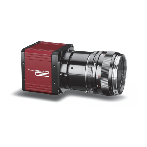
- Page 1 AVT Prosilica GE Technical Manual AVT GigE Vision Cameras V2.0.2 02 October 2013 Allied Vision Technologies GmbH Taschenweg 2a D-07646 Stadtroda, Germany...
-
Page 2: Legal Notice
Allied Vision Technologies customers using or selling these products for use in such applications do so at their own risk and agree to fully indemnify Allied Vision Technologies for any damages resulting from such improper use or sale. -
Page 3: Table Of Contents
Contents Contacting Allied Vision Technologies ........... 5 Introduction ......................6 Document history......................6 Conventions used in this manual ..................7 Styles ........................7 Symbols ........................7 Precautions........................8 Cleaning optics ....................... 9 Identifying debris ....................... 9 Locating debris ......................9 Color cameras with IR filter ................... - Page 4 Adjustment of F-Mount....................39 Attach F-Mount compatible lens .................. 39 Loosen F-Mount front assembly ................... 39 Image to infinity....................... 39 Camera interfaces .....................40 Status LEDs ........................40 Gigabit Ethernet port ..................... 41 Camera I/O connector pin assignment ................42 I/O definition ....................... 43 Camera power ......................
-
Page 5: Contacting Allied Vision Technologies
38 Washington Street Newburyport, MA 01950, USA Toll Free number +1 877-USA-1394 Tel: +1 978-225-2030 Fax: +1 978-225-2029 e-mail: info@alliedvisiontec.com Allied Vision Technologies Asia Pte. Ltd. 82 Playfair Road #07-02 D’Lithium, Singapore 368001 Tel: +65 6634-9027 Fax: +65 6634-9029 e-mail: info@alliedvisiontec.com Allied Vision Technologies (Shanghai) Co. -
Page 6: Introduction
Introduction Introduction This AVT Prosilica GE Technical Manual describes in depth the technical speci- fications of the Prosilica GE camera family including dimensions, feature over- view, I/O definition, trigger timing waveforms, and frame rate performance. For information on software installation read the AVT GigE Installation Man- ual. -
Page 7: Conventions Used In This Manual
Introduction Version Date Remarks V2.0.2 2013-Oct-02 • Added optical flange focal distance and maximum lens protrusion informa- tion on page36 • Added a note on locking screw cables on page 41 • Updated Cleaning optics section • Updated vertical binning values in the Specifications chapter •... -
Page 8: Precautions
Introduction This symbol highlights URLs for further information. The URL itself is shown in blue. Example: http://www.alliedvisiontec.com Precautions Caution Do not disassemble the camera housing. Warranty is void if camera has been disassembled. This camera contains sensitive internal components. Caution Keep shipping material. -
Page 9: Cleaning Optics
Introduction Cleaning optics Caution AVT does not warranty against any physical damage to the sen- sor/filter/protection glass or lenses. Use utmost care when cleaning optical components. Caution Do not touch any optics with fingers. Oil from fingers can damage fragile optical coatings. ... -
Page 10: Cleaning With Air
Introduction Note A pin spanner wrench suitable for IR filter removal is available for purchase from AVT. AVT P/N: E9020001 Cleaning with air Blow directly on the contaminated surface with moderate pressure, clean com- pressed air. Caution Do not exceed 6 bar (90 psi). If using canned air, approxi- mately ~ 4.8 bar (70 psi) when full, do not shake or tilt the ... -
Page 11: Conformity
Conformity Conformity Allied Vision Technologies declares under its sole responsibility that all stan- dard cameras of the AVT Prosilica GE family to which this declaration relates are in conformity with the following standard(s) or other normative docu- ment(s): • CE, following the provisions of 2004/108/EG directive •... -
Page 12: Specifications
Specifications Specifications Prosilica GE680/680C Feature Specification Resolution 640 x 480 Sensor Truesense KAI-0340 Type CCD Progressive Sensor size Type 1/3 Cell size 7.4 μm Lens mount C (adjustable) Max frame rate at full resolution 205 fps 12 bit On-board FIFO 32 MB Bit depth 8/12... - Page 13 Specifications Measured with clear cover glass 1000 1100 Wavelength [nm] Figure 1: Prosilica GE680 monochrome spectral response Green Blue Measured with 0.45 clear cover glass 0.35 0.25 0.15 0.05 1000 1100 Wavelength [nm] Figure 2: Prosilica GE680C color spectral response (without IR cut filter) Prosilica GE Technical Manual V2.0.2...
-
Page 14: Prosilica Ge1050/1050C
Specifications Prosilica GE1050/1050C Feature Specification Resolution 1024 x 1024 Sensor Truesense KAI-01050 Type CCD Progressive Sensor size Type 1/2 Cell size 5.5 μm Lens mount C (adjustable) Max frame rate at full resolution 59 fps 12 bit On-board FIFO 32 MB Bit depth 8/12 Mono formats... - Page 15 Specifications Measured with AR coated cover glass 350 400 450 500 550 600 650 700 750 800 850 900 950 1000 1050 1100 Wavelength [nm] Figure 3: Prosilica GE1050 monochrome spectral response Green Blue 0.45 Measured with AR coated cover glass 0.35 0.25 0.15...
-
Page 16: Prosilica Ge1650/1650C
Specifications Prosilica GE1650/1650C Feature Specification Resolution 1600 x 1200 Sensor Truesense KAI-2020 Type CCD Progressive Sensor size 1 inch Cell size 7.4 μm Lens mount C (adjustable) Max frame rate at full resolution 32 fps 12 bit On-board FIFO 32 MB Bit depth 8/12 Mono formats... - Page 17 Specifications 1000 1150 Wavelength [nm] Figure 5: Prosilica GE1650 monochrome spectral response Green Blue 0.45 0.35 0.25 0.15 0.05 950 1000 Wavelength [nm] Figure 6: Prosilica GE1650C color spectral response (without IR cut filter) Prosilica GE Technical Manual V2.0.2...
-
Page 18: Prosilica Ge1660/1660C
Specifications Prosilica GE1660/1660C Feature Specification Resolution 1600 x 1200 Sensor Truesense KAI-2050 Type CCD Progressive Sensor size 2/3 inch Cell size 5.5 μm Lens mount C (adjustable) Max frame rate at full resolution 34.6 fps 12 bit On-board FIFO 32 MB Bit depth 8/12 Mono formats... - Page 19 Specifications Measured with AR coated cover glass 1100 Wavelength [nm] Figure 7: Prosilica GE1660 monochrome spectral response Green Blue Measured with AR 0.45 coated cover glass 0.35 0.25 0.15 0.05 1000 1100 Wavelength [nm] Figure 8: Prosilica GE1660C color spectral response (without IR cut filter) Prosilica GE Technical Manual V2.0.2...
-
Page 20: Prosilica Ge1900/1900C
Specifications Prosilica GE1900/1900C Feature Specification Resolution 1920 x 1080 Sensor Truesense KAI-2093 Type CCD Progressive Sensor size 1 inch Cell size 7.4 μm Lens mount C (adjustable) Max frame rate at full resolution 30 fps 12 bit On-board FIFO 32 MB Bit depth 8/12 Mono formats... - Page 21 Specifications Without cover glass With cover glass Without cover glass without microlens 0.45 0.35 0.25 0.15 0.05 1000 Wavelength [nm] Figure 9: Prosilica GE1900 monochrome spectral response Green Blue Measured with clear cover glass 0.35 0.25 0.15 0.05 1000 Wavelength [nm] Figure 10: Prosilica GE1900C color spectral response (without IR cut filter) Prosilica GE Technical Manual V2.0.2...
-
Page 22: Prosilica Ge1910/1910C
Specifications Prosilica GE1910/1910C Feature Specification Resolution 1920 x 1080 Sensor Truesense KAI-02150 Type CCD Progressive Sensor size 2/3 inch Cell size 5.5 μm Lens mount C (adjustable) Max frame rate at full resolution 32 fps 12 bit On-board FIFO 32 MB Bit depth 8/12 Mono formats... - Page 23 Specifications Measured with AR coated cover glass 1050 Wavelength [nm] Figure 11: Prosilica GE1910 monochrome spectral response Green Blue Measured with clear cover glass 1075 Wavelength [nm] Figure 12: Prosilica GE1910C color spectral response (without IR cut filter) Prosilica GE Technical Manual V2.0.2...
-
Page 24: Prosilica Ge2040/2040C
Specifications Prosilica GE2040/2040C Feature Specification Resolution 2040 x 2048 Sensor Truesense KAI- 04022 Type CCD Progressive Sensor size 1.2 inch Cell size 7.4 μm Lens mount C (adjustable) / F Max frame rate at full resolution 15 fps 12 bit On-board FIFO 32 MB Bit depth... - Page 25 Specifications Measured with glass 350 400 450 500 550 600 650 700 750 800 850 900 950 1000 Wavelength [nm] Figure 13: Prosilica GE2040 monochrome spectral response Green Blue Measured with glass 0.45 0.35 0.25 0.15 0.05 1000 Wavelength [nm] Figure 14: Prosilica GE2040C color spectral response (without IR cut filter) Prosilica GE Technical Manual V2.0.2...
-
Page 26: Prosilica Ge4000/4000C
Specifications Prosilica GE4000/4000C Feature Specification Resolution 4008 x 2972 Sensor Truesense KAI-11002 Type CCD Progressive Sensor size 35 mm Cell size 9 μm Lens mount Max frame rate at full resolution 5 fps 12 bit On-board FIFO 32 MB Bit depth 8/12 Mono formats GE4000: Mono8, Mono12, Mono12Packed... - Page 27 Specifications 1000 Wavelength [nm] Figure 15: Prosilica GE4000 monochrome spectral response Green Blue 0.45 0.35 0.25 0.15 0.05 1000 Wavelength [nm] Figure 16: Prosilica GE4000C color spectral response (without IR cut filter) Prosilica GE Technical Manual V2.0.2...
-
Page 28: Prosilica Ge4900/4900C
Specifications Prosilica GE4900/4900C Feature Specification Resolution 4872 x 3248 Sensor Truesense KAI-16000 Type CCD Progressive Sensor size 35 mm Cell size 7.4 μm Lens mount Max frame rate at full resolu- 3 fps tion 12 bit On-board FIFO 32 MB Bit depth 8/12 Mono formats... - Page 29 Specifications Measured with AR 0.45 coated cover glass 0.35 0.25 0.15 0.05 1100 Wavelength [nm] Figure 17: Prosilica GE4900 monochrome spectral response Green Blue 0.45 Measured without AR coated cover glass 0.35 0.25 0.15 0.05 1000 1100 Wavelength [nm] Figure 18: Prosilica GE4900C color spectral response (without IR cut filter) Prosilica GE Technical Manual V2.0.2...
-
Page 30: Camera Attribute Highlights
Camera attribute highlights Camera attribute highlights AVT cameras support a number of standard and extended features. The table below identifies a selection of interesting capabilities of the Prosilica GE camera family. A complete listing of camera controls, including control defini- tions can be found online: ... -
Page 31: Filters
Filters Filters All Prosilica GE color models are equipped with an infrared block filter (IR fil- ter). This filter is employed to prevent infrared wavelength photons from pass- ing to the sensor. In the absence of IR filter, images are dominated by red and incapable of being properly color balanced. -
Page 32: Camera Dimensions
Camera dimensions Camera dimensions Prosilica GE C-Mount (adjustable) GE680/680C, GE1050/1050C, GE1650/1650C, GE1660/1660C, GE1900/1900C, GE1910/1910C, GE2040/2040C M3x4 (4x) M3x3 (2x) 13.9* 80.4* M3x3 (4x) *Nominal value. Add 0.3mm for color cameras. 51.6 39.4 Figure 20: Prosilica GE adjustable C-Mount models mechanical dimensions Prosilica GE Technical Manual V2.0.2... -
Page 33: Prosilica Ge F-Mount: Ge2040/2040C
Camera dimensions Prosilica GE F-Mount: GE2040/2040C 59.7 M3x3 (2x) 42.3* M3x3 (4x) *Nominal value. Add 0.3mm for color cameras. 51.6 39.4 Figure 21: Prosilica GE F-Mount mechanical dimensions Prosilica GE Technical Manual V2.0.2... -
Page 34: Prosilica Ge Large Format F-Mount: Ge4000/4000C, Ge4900/4900C
Camera dimensions Prosilica GE large format F-Mount: GE4000/ 4000C, GE4900/4900C 59.7 109.7* 50 TYP M3x3 (16x) 26 TYP *Nominal value. Add 0.3mm for color cameras. Figure 22: Prosilica GE large format F-Mount mechanical dimensions Prosilica GE Technical Manual V2.0.2... -
Page 35: Tripod Adapter
Camera dimensions Tripod adapter A Prosilica GE camera can be mounted on a camera tripod by using a mounting plate P/N 02-5000A. The same mounting plate can be used for all models within the GE camera family. Note Prosilica GE tripod mount is available for purchase from AVT. AVT P/N: 02-5000A ... -
Page 36: Optical Flange Focal Distance
Camera dimensions Optical flange focal distance Optical flange focal distance is the optical distance from the mounting flange to the image sensor die (see figure 24 and figure 25). Optical flange focal distance can be calculated as: IR cut filter thickness Sensor window thickness –... -
Page 37: F-Mount Cross Section
Camera dimensions Nominal flange focal Camera Lens protrusion [mm] IR cut filter* [mm] Sensor window [mm] distance [mm] GE1660C 9.67 1.00 0.76 18.11 GE1900 13.64 0.76 17.78 GE1900C 9.15 1.00 0.76 18.11 GE1910 13.64 0.76 17.78 GE1910C 9.67 1.00 0.76 18.11 GE2040 13.64... -
Page 38: Adjustment Of C-Mount
Camera dimensions Adjustment of C-Mount Prosilica GE cameras are shipped with an adjustable C-Mount, F-Mount, or CS-Mount depending on sensor size and camera order code. See AVT Modular Concept for more information: http://www.alliedvisiontec.com/us/support/downloads/ product-literature/avt-modular-concept.html The C-Mount or CS-Mount is adjusted at the factory and should not require adjusting. -
Page 39: Adjustment Of F-Mount
Camera dimensions Adjustment of F-Mount The F-Mount is adjusted at the factory and should not require adjusting. If for some reason, the lens mount requires adjustment, use the following method. M3 SET SCREW: 3 PLACES F-MOUNT FRONT ASSEMBLY Figure 27: Prosilica GE F-Mount isometric view Attach F-Mount compatible lens Use an F-Mount compatible lens that allows an infinity focus. -
Page 40: Camera Interfaces
Camera interfaces Camera interfaces This chapter provides information on Gigabit Ethernet port, inputs and outputs, and trigger features. For more information on GigE accessories: http://www.alliedvisiontec.com/emea/products/ accessories/gige-accessories.html GIGABIT ETHERNET CABLE MOUNTING HOLES LED1 LED2 GIGABIT ETHERNET PORT I/O PORT: EXTERNAL SYNC IO RS-232 TX/RX CAMERA POWER IN 1... -
Page 41: Gigabit Ethernet Port
Camera interfaces Gigabit Ethernet port The Gigabit Ethernet port conforms to the IEEE 802.3 1000BASE-T standard for Gigabit Ethernet over copper. AVT recommends using Category 6 or higher com- patible cabling and connectors for best performance. The AVT GigE Installation Manual offers detailed instructions for using Prosilica GE cameras. -
Page 42: Camera I/O Connector Pin Assignment
Camera interfaces Camera I/O connector pin assignment Pin Signal Direction Level Description In 1 TTL max. 5 V Camera input galvanic isolated (SyncIn1) 12 11 Out 2 TTL max. 5 V Camera output 2 galvanic isolated (SyncOut2) Out 3 TTL max. 5 V Camera output 3 galvanic isolated (SyncOut3) RxD RS-232... -
Page 43: I/O Definition
Camera interfaces I/O definition Camera power The Prosilica GE camera family supports a wide input power voltage range. The camera will not power in reverse polarity. Exceeding the voltage range specified below will damage the camera. Caution 5–24 V. 12 V nominal. ... -
Page 44: Output Signals
Camera interfaces Caution Do not exceed 5.5 V on In 1. The Mini-SMB trigger input is internally connected to the In 1 of the general purpose I/O port. The Mini-SMB port on the camera uses an Amphenol 903- 406J-51R connector. A suitable mating cable connector is Amp 413985-3 which can be used with RG174 coaxial cable. -
Page 45: Video Iris
Camera interfaces Out 2 and Out 3 Out 2 and Out 3 can be configured to active high or active low. The internal cam- era signals are listed as follows: Exposing Corresponds to when camera is integrating light Trigger Ready Indicates when the camera will accept a trigger signal Trigger Input A relay of the trigger input signal used to “daisy chain”... -
Page 46: Camera I/O Connector Internal Circuit Diagram
Camera interfaces Camera I/O connector internal circuit diagram TRIGGER INPUT SYNC OUT 2 SYNC OUT 3 RS-232 RXD RS-232 TXD CAMERA INTERNAL CIRCUIT ISO+5V ISO+5V VDD -3.3 IL7 16-3 HIROSE HR10A-10R-12SB VDD1 VDD2 GND2 GND1 AS SEEN FROM OUT1 LOGIC SYNC OUT 1 TEXAS INSTRUMENTS CAMERA REAR VIEW OUT2... -
Page 47: Camera I/O Connector External Circuit Example
Camera interfaces Camera I/O connector external circuit example CABLE SIDE TRIGGER INPUT IN 1 (5 V TTL DRIVER) OUT 2 OUT 2 (5 V TTL RECEIVER) OUT 3 OUT 3 (5 V TTL RECEIVER) HIROSE HR10A-10P-12P Figure 31: Prosilica GE external circuit The trigger circuit is connected to a Texas Instruments SN74ACT244PWR buffer/ driver inside the camera. -
Page 48: In 1, Out 1 External Circuit Example
Camera interfaces In 1, Out 1 external circuit example RG-174 COAX CABLE MINI-SMB TRIGGER INPUT IN 1 (5 V TTL DRIVER) RG-174 COAX CABLE MINI-SMB OUT 1 OUT 1 (5 V TTL RECEIVER) Figure 32: Prosilica GE In 1, Out 1 external circuit The trigger circuit is connected to a Texas Instruments SN74ACT244PWR buffer/ driver inside the camera. -
Page 49: Trigger Timing Diagram
Camera interfaces Trigger timing diagram Readout time Trigger latency Exposure Registered exposure start delay User trigger time Note: Jitter at the Logic trigger beginning of an exposure has no effect on the length of exposure. N+ 1 Exposure Trigger jitter N+ 1 Readout Interline time... - Page 50 Camera interfaces Term Definition Trigger ready Indicates to the user that the camera will accept the next trigger Registered exposure time Exposure time value currently stored in the camera memory Exposure start delay Registered exposure time subtracted from the read- out time and indicates when the next exposure cycle can begin such that the exposure will end after the current readout...
-
Page 51: Firmware Update
Firmware update Firmware update Firmware updates are carried out via the GigE connection. AVT provides an application for all Prosilica GE cameras that loads firmware to the camera using a simple interface. New feature introductions and product improvements moti- vate new firmware releases. All users are encouraged to use the newest firm- ware available and complete the firmware update if necessary. -
Page 52: Resolution And Roi Frame Rates
Resolution and ROI frame rates Resolution and ROI frame rates This section provides the performance information which identifies the impact of reducing the region of interest on the camera’s maximum frame rate. Note • Frame rate data was generated using StreamBytesPer- Second = 124 MB/s and an 8 bit pixel format such as ... -
Page 53: Prosilica Ge1050
Resolution and ROI frame rates Prosilica GE1050 Frame rate ------------------------------------------------------------------------ - 11.72 μs Height 4948.66 μs 1050 Height [pixels] Figure 35: Frame rate vs. height for Prosilica GE1050 Prosilica GE1650 Frame rate ------------------------------------------------------------------------ - 17.61 μs Height 10119.0 μs 1000 1200 Height [pixels]... -
Page 54: Prosilica Ge1660
Resolution and ROI frame rates Prosilica GE1660 Frame rate ------------------------------------------------------------------------ - 17.99 μs Height 7398.16 μs 1000 1200 Height [pixels] Figure 37: Frame rate vs. height for Prosilica GE1660 Prosilica GE1900 Frame rate --------------------------------------------------------------------------- - 18.31 μs Height 13114.72 μs 1000 1100 Height [pixels]... -
Page 55: Prosilica Ge1910
Resolution and ROI frame rates Prosilica GE1910 Frame rate ------------------------------------------------------------------------ - 21.35 μs Height 7526.47 μs 1000 1100 Height [pixels] Figure 39: Frame rate vs. height for Prosilica GE1910 Prosilica GE2040 Frame rate --------------------------------------------------------------------------- - 15.63 μs Height 33773.85 μs 1200 1500... -
Page 56: Prosilica Ge4000
Resolution and ROI frame rates Prosilica GE4000 Frame rate --------------------------------------------------------------------------- - 52.45 μs Height 56713.22 μs 1200 1500 1800 2100 2400 2700 Height [pixels] Figure 41: Frame rate vs. height for Prosilica GE4000 Prosilica GE4900 Frame rate --------------------------------------------------------------------------- - ... -
Page 57: Prosilica Ge Model Comparison
Resolution and ROI frame rates Prosilica GE model comparison GE1050 GE1650 GE1660 GE1900 GE1910 1000 1200 Height [pixels] Figure 43: Maximum frame rate vs. height for select Prosilica GE camera models GE4000 GE4900 1200 1500 1800 2100 2400 2700 3000 3300 Height [pixels] Figure 44: Maximum frame rate vs. -
Page 58: Additional References
Additional references Additional references Prosilica GE webpage http://www.alliedvisiontec.com/us/products/cameras/gigabit-ethernet/ prosilica-ge.html Prosilica GE Documentation http://www.alliedvisiontec.com/us/support/downloads/product-literature/ prosilica-ge.html AVT VIMBA SDK http://www.alliedvisiontec.com/us/products/software/vimba-sdk.html AVT GigE PvAPI SDK http://www.alliedvisiontec.com/us/products/legacy.html AVT Knowledge Base http://www.alliedvisiontec.com/us/support/knowledge-base.html AVT Case Studies http://www.alliedvisiontec.com/us/products/applications/industrial- inspection.html Prosilica GE Firmware http://www.alliedvisiontec.com/us/support/downloads/firmware.html Prosilica GE Technical Manual V2.0.2... -
Page 59: Index
Index Index Multicast ..........30 Camera interfaces ........40 CE............11 Cleaning optics .......... 9 Optical flange focal distance....... 36 Copyright..........2 Precautions ..........8 Declaration of conformity......11 Propagation delay (trigger) ......49 Document history ........6 Reading out data (trigger)......50 Environmental specifications ...... - Page 60 Index Status LEDs ..........40 StreamBytesPerSecond ......52 Styles............7 Symbols............ 7 Time delay (trigger) ........49 Tpd (definition)........49 Trademarks ..........2 Trigger jitter (definition) ......49 Trigger latency (definition) ......49 trigger ready (signal) ........ 50 Trigger rules ..........50 Trigger timing diagram ......
Need help?
Do you have a question about the AVT Prosilica GE and is the answer not in the manual?
Questions and answers