
Related Manuals for Allied Vision Technologies Prosilica GB650


Summary of Contents for Allied Vision Technologies Prosilica GB650
- Page 1 AVT Prosilica GB Technical Manual AVT GigE Vision Cameras V2.0.3 05 July 2013 Allied Vision Technologies GmbH Taschenweg 2a D-07646 Stadtroda, Germany...
-
Page 2: Legal Notice
Allied Vision Technologies customers using or selling these products for use in such applications do so at their own risk and agree to fully indemnify Allied Vision Technologies for any damages resulting from such improper use or sale. -
Page 3: Table Of Contents
Color cameras with IR filter ................... 9 Cleaning with air....................... 10 Contact cleaning....................... 10 Conformity ......................11 Specifications .......................12 Prosilica GB650/650C ....................12 Prosilica GB660/660C ....................14 Prosilica GB1380/1380C ....................16 Prosilica GB2450/2450C ....................18 Camera attribute highlights ................20 Filters ........................21 Camera dimensions ..................22... - Page 4 Video iris user circuit example..................37 Trigger timing diagram....................38 Notes on triggering ....................38 Firmware update ....................40 Resolution and ROI frame rates ...............41 Prosilica GB650......................41 Prosilica GB660......................42 Prosilica GB1380......................42 Prosilica GB2450......................43 Prosilica GB model comparison ..................43 Additional references ..................44 Index ...........................45...
-
Page 5: Contacting Allied Vision Technologies
38 Washington Street Newburyport, MA 01950, USA Toll Free number +1 877-USA-1394 Tel: +1 978-225-2030 Fax: +1 978-225-2029 e-mail: info@alliedvisiontec.com Allied Vision Technologies Asia Pte. Ltd. 82 Playfair Road #07-02 D’Lithium, Singapore 368001 Tel: +65 6634-9027 Fax: +65 6634-9029 e-mail: info@alliedvisiontec.com Allied Vision Technologies (Shanghai) Co. -
Page 6: Introduction
Updated AVT recommended cabling to category 6 or higher in Gigabit Ethernet port section V2.0.3 2013-Jul-05 • Added contact information for Allied Vision Technologies (Shanghai) Co. Ltd. • Updated the links to AVT GigE Installation Manual • Added links to AVT GigE Camera and Driver Features document Table 1: Document history Prosilica GB Technical Manual V2.0.3... -
Page 7: Conventions Used In This Manual
Introduction Conventions used in this manual To give this manual an easily understood layout and to emphasize important information, the following typographical styles and symbols are used: Styles Style Function Example Bold Programs, inputs, or bold highlighting important information Input Courier Code listings etc. -
Page 8: Precautions
Introduction Precautions Caution Do not disassemble the camera housing. Warranty is void if camera has been disassembled. This camera contains sensitive internal components. Caution Keep shipping material. Poor packaging of the product may cause damage during ship- ping. Caution Verify all external connections. -
Page 9: Cleaning Optics
Introduction Cleaning optics Caution Do not touch any optics with fingers. Oil from fingers can damage fragile optical coatings. Identifying debris Debris on the image sensor or optical components appears as a darkened area or smudge on a camera image. Do not confuse this with a pixel defect which appears as a distinct point. -
Page 10: Cleaning With Air
Introduction Cleaning with air Blow directly on the contaminated surface with moderate pressure, clean com- pressed air. Caution Do not exceed 90 psi. If using canned air (typically ~ 70 psi when full), do not shake or tilt the can, as extreme changes ... -
Page 11: Conformity
Conformity Conformity Allied Vision Technologies declares under its sole responsibility that all stan- dard cameras of the AVT Prosilica GB family to which this declaration relates are in conformity with the following standard(s) or other normative docu- ment(s): • CE, following the provisions of 2004/108/EG directive •... -
Page 12: Specifications
10 ns for non-isolated I/O, 1.3 μs for isolated I/O Operating humidity 20 to 80% non-condensing Hardware interface standard IEEE 802.3 1000BASE-T, 100BASE-TX Software interface standard GigE Vision Standard 1.2 Regulatory CE, FCC Class A, RoHS (2011/65/EU) Table 3: Prosilica GB650/650C camera specifications Prosilica GB Technical Manual V2.0.3... - Page 13 Specifications 1000 Wavelength [nm] Figure 1: Prosilica GB650 monochrome spectral response Green Blue Wavelength [nm] Figure 2: Prosilica GB650C color spectral response Prosilica GB Technical Manual V2.0.3...
-
Page 14: Prosilica Gb660/660C
Specifications Prosilica GB660/660C Feature Specification Resolution 659 x 493 Sensor Sony ICX618 Type CCD Progressive Sensor size Type 1/4 Cell size 5.6 μm Lens mount C (adjustable) / CS Max frame rate at full resolution 119 fps 14 bit On-board FIFO 16 MB Bit depth 8/12... - Page 15 Specifications 1000 Wavelength [nm] Figure 3: Prosilica GB660 monochrome spectral response Green Blue Wavelength [nm] Figure 4: Prosilica GB660C color spectral response Prosilica GB Technical Manual V2.0.3...
-
Page 16: Prosilica Gb1380/1380C
Specifications Prosilica GB1380/1380C Feature Specification Resolution 1360 x 1024 Sensor Sony ICX285AL CCD (ICX285AQ for color) Type CCD Progressive Sensor size Type 2/3 Cell size 6.45 μm Lens mount C (adjustable) / CS Max frame rate at full resolution 30 fps 14 bit On-board FIFO 16 MB... - Page 17 Specifications 1000 Wavelength [nm] Figure 5: Prosilica GB1380 monochrome spectral response Green Blue Wavelength [nm] Figure 6: Prosilica GB1380C color spectral response Prosilica GB Technical Manual V2.0.3...
-
Page 18: Prosilica Gb2450/2450C
Specifications Prosilica GB2450/2450C Feature Specification Resolution 2448 x 2050 Sensor Sony ICX625 Type CCD Progressive Sensor size Type 2/3 Cell size 3.45 μm Lens mount C (adjustable) / CS Max frame rate at full resolution 15 fps 14 bit On-board FIFO 16 MB Bit depth 8/12... - Page 19 Specifications 1000 Wavelength [nm] Figure 7: Prosilica GB2450 monochrome spectral response Green Blue Wavelength [nm] Figure 8: Prosilica GB2450C color spectral response Prosilica GB Technical Manual V2.0.3...
-
Page 20: Camera Attribute Highlights
Camera attribute highlights Camera attribute highlights AVT cameras support a number of standard and extended features. The table below identifies a selection of interesting capabilities of the Prosilica GB cam- era family. A complete listing of camera controls, including control defini- tions can be found online: ... -
Page 21: Filters
Filters Filters All Prosilica GB color models are equipped with an infrared block filter (IR fil- ter). This filter is employed to prevent infrared wavelength photons from pass- ing to the sensor. In the absence of IR filter, images are dominated by red and incapable of being properly color balanced. -
Page 22: Camera Dimensions
Camera dimensions Camera dimensions The Prosilica GB camera is a board level product which offers several sensor and connector orientation options. The camera variations are described below and detailed dimension drawings are provided in the next section. Sensor orientation Model Description Example Landscape... -
Page 23: Mechanical Drawings
Mechanical drawings Mechanical drawings Landscape sensor and inline connector 50.8 45.7 2 PLCS TYP 6 PLCS TYP 19.1 15.7 M2.5x0.45 ITEM 1: 3M 10214-55G3PC 2 PLCS TYP ITEM 2: HALO HFJ11-1G16E-L12RL ITEM 3: SONY ICX285 13.6 15.9 23.6 29.5 Figure 10: Prosilica GB1380/GB1380C mechanical drawing Prosilica GB Technical Manual V2.0.3... -
Page 24: Landscape Sensor And Vertical Connector
Mechanical drawings Landscape sensor and vertical connector 50.8 45.7 2 PLCS TYP 6 PLCS TYP 19.1 13.5 M2.5x0.45 29.5 2 PLCS TYP 23.6 ITEM 1: 3M 10214-6212PC 15.7 ITEM 2: HALO HFJV1-E1G16-L12RL ITEM 3: SONY ICX285 16.5 Figure 11: Prosilica GB1380-V/GB1380C-V mechanical drawing Prosilica GB Technical Manual V2.0.3... -
Page 25: Portrait Sensor And Inline Connector
Mechanical drawings Portrait sensor and inline connector 50.8 45.7 6 PLCS TYP 31.2 19.1 2 PLCS TYP 15.7 M2.5x0.45 2 PLCS TYP ITEM 1: 3M 10214-55G3PC ITEM 2: HALO HFJ11-1G16E-L12RL 13.6 ITEM 3: SONY ICX285 15.9 23.6 29.5 Figure 12: Prosilica GB1380-P/GB1380C-P mechanical drawing Prosilica GB Technical Manual V2.0.3... -
Page 26: Portrait Sensor And Vertical Connector
Mechanical drawings Portrait sensor and vertical connector 50.8 45.7 6 PLCS TYP 31.2 19.1 2 PLCS TYP M2.5x0.45 13.5 2 PLCS TYP 29.5 23.6 15.7 ITEM 1: 3M 10214-6212PC ITEM 2: HALO HFJV1-E1G16-L12RL ITEM 3: SONY ICX285 16.5 Figure 13: Prosilica GB1380-PV/GB1380C-PV mechanical drawing Prosilica GB Technical Manual V2.0.3... -
Page 27: Camera Lens Mount
Mechanical drawings Camera lens mount 21.3* 16.5 11.4 38.1 26.7 32.5 *Nominal value Add 0.3 mm for color cameras lens mount Figure 14: Prosilica GB Prosilica GB Technical Manual V2.0.3... -
Page 28: Adjustment Of Lens Mount
Mechanical drawings Adjustment of lens mount Prosilica GB cameras can be equipped with an adjustable C- Mount or a CS-Mount depending on sensor size and camera order code. AVT Modular Concept for more information: http://www.alliedvisiontec.com/us/support/downloads/ product-literature/avt-modular-concept.html The C-Mount or CS-Mount is adjusted at the factory and should not require adjusting. -
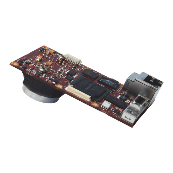
Page 29: Camera Interfaces
Camera interfaces Camera interfaces This chapter provides information on Gigabit Ethernet port, inputs and outputs, and trigger features. For more information on GigE accessories: http://www.alliedvisiontec.com/emea/products/ accessories/gige-accessories.html GIGABIT ETHERNET PORT I/O PORT: CAMERA POWER EXTERNAL SYNC IO RS232 TX/RX LED2 LED1 Figure 16: Prosilica GB connection ports Status LEDs... -
Page 30: Gigabit Ethernet Port
Camera interfaces Gigabit Ethernet port The Gigabit Ethernet port conforms to the IEEE 802.3 1000BASE-T standard for Gigabit Ethernet over copper. We recommend using Category 6 or higher com- patible cabling and connectors for best performance. The AVT GigE Installation Manual offers detailed instructions for using Prosilica GB cameras. -
Page 31: Camera I/O Connector Pin Assignment
Camera interfaces Camera I/O connector pin assignment Pin Signal Direction Level Description Camera Power In 5–16* VDC Power supply Camera GND GND for ext. power Ground for camera power supply In 1 (high) = 5–24 V Input 1 opto-isolated (SyncIn1) (low) = 0–0.8 V Isolated IO In/Out... -
Page 32: I/O Definition
Camera interfaces I/O definition Camera power The Prosilica GB camera family has recently been updated to offer an expanded input power voltage range. The camera serial number is used to differentiate between cameras that offer 5–16 VDC and those that offer 5–25 VDC. Caution SN: 02-22XXA, 5–16 V. -
Page 33: Input Triggers
Camera interfaces Input triggers Input triggers allow the camera to be synchronized to an external event. The camera can be programmed to trigger on the rising edge, falling edge, both edges, or level of the signal. The camera can also be programmed to capture an image at some programmable delay time after the trigger event. -
Page 34: Signal Ground
Camera interfaces Out 1 – opto-isolated Out 1 is optically isolated and should be used in noisy environments. Out 1 requires a pull up resistor of greater than 1 KΩ to the user’s 5 V logic supply. Tie Camera GND to Isolated IO GND to complete the external circuit. See Camera I/ O opto-isolated user circuit example for more information. -
Page 35: Camera I/O Opto-Isolated User Circuit Example
Camera interfaces Camera I/O opto-isolated user circuit example CABLE SIDE Out1 Isolated IO GND Camera GND Camera GND Camera Power Camera Power In1(Driver) 3M 10114-3000PE User Power RECOMMENDED VALUES USER POWER 1 K Ω Out1 (Receiver) 12 V 0.7 KΩ 2.7 KΩ... -
Page 36: Camera I/O Non-Isolated User Circuit Example
Camera interfaces Camera I/O non-isolated user circuit example CABLE SIDE CAMERA GND CAMERA POWER 3M 10114-3000PE IN 2 (3.3 V DRIVER) OUT 2 (3.3 V RECEIVER) Figure 19: Prosilica GB non-isolated trigger user circuit Caution Input: Incoming trigger must be able to source 10 μA, at 3.3 V. Input trigger voltage greater than 5.5 V will damage the cam- ... -
Page 37: Video Iris User Circuit Example
Camera interfaces Video iris user circuit example Prosilica GB series cameras provide built-in auto iris controls for controlling video-type auto-iris lenses. These lenses are available from many popular secu- rity lens companies including Pentax, Fujinon, Tamron, Schneider and others. Remote iris lens control allows the camera to be more adaptable to changing light conditions. -
Page 38: Trigger Timing Diagram
Camera interfaces Trigger timing diagram Readout time Trigger latency Exposure Registered exposure start delay User trigger time Note: Jitter at the Logic trigger beginning of an exposure has no effect on the length of exposure. Exposure N+ 1 Trigger jitter Readout N+ 1 Interline time... - Page 39 Camera interfaces Term Definition Trigger ready Indicates to the user that the camera will accept the next trigger. Registered exposure Exposure time value currently stored in the camera time memory Exposure start delay Registered exposure time subtracted from the read- out time and indicates when the next exposure cycle can begin such that the exposure will end after the current readout...
-
Page 40: Firmware Update
Firmware update Firmware update Firmware updates are carried out via the GigE connection. AVT provides an application for all Prosilica GB cameras that loads firmware to the camera using a simple interface. New feature introductions and product improvements moti- vate new firmware releases. All users are encouraged to use the newest firm- ware available and complete the firmware update if necessary. -
Page 41: Resolution And Roi Frame Rates
(less overall height with same field of view). • There is no frame rate increase with reduced width. Prosilica GB650 Frame rate ------------------------------------------------------------------------ - 14.39 μs Height 1114.28 μs Height [pixels] Figure 22: Frame rate vs. height for Prosilica GB650 Prosilica GB Technical Manual V2.0.3... -
Page 42: Prosilica Gb660
Resolution and ROI frame rates Prosilica GB660 Frame rate ------------------------------------------------------------------------ - 13.26 μs Height 1844.78 μs Height [pixels] Figure 23: Frame rate vs. height for Prosilica GB660 Prosilica GB1380 Frame rate ------------------------------------------------------------------------ - 27.79 μs Height 4881.40 μs 1050 Height [pixels] Figure 24: Frame rate vs. -
Page 43: Prosilica Gb2450
Resolution and ROI frame rates Prosilica GB2450 Frame rate --------------------------------------------------------------------------- - 26.63 μs Height 12079.91 μs 1200 1500 1800 2100 Height [pixels] Figure 25: Frame rate vs. height for Prosilica GB2450 Prosilica GB model comparison GB650 GB660 GB1380 GB2450 1000 1200 1500... -
Page 44: Additional References
Additional references Additional references Prosilica GB webpage http://www.alliedvisiontec.com/us/products/cameras/gigabit-ethernet/ prosilica-gb.html Prosilica GB Documentation http://www.alliedvisiontec.com/us/support/downloads/product-literature/ prosilica-gb.html AVT VIMBA SDK http://www.alliedvisiontec.com/us/products/software/vimba-sdk.html AVT GigE PvAPI SDK http://www.alliedvisiontec.com/us/products/software/avt-pvapi-sdk.html AVT Knowledge Base http://www.alliedvisiontec.com/us/support/knowledge-base.html AVT Case Studies http://www.alliedvisiontec.com/us/products/applications/industrial- inspection.html Prosilica GB Firmware http://www.alliedvisiontec.com/us/support/downloads/firmware.html Prosilica GB Technical Manual V2.0.3... -
Page 45: Index
Prosilica GB1380C ....... 17 Integrating light (trigger) ......38 Prosilica GB2450......... 19 Interline boundary........39 Prosilica GB2450C ....... 19 Interline time (signal) ....... 39 Prosilica GB650 ........13 Isolated IO GND......31 Prosilica GB650C......... 13 Prosilica GB660 ........15 Prosilica GB660C......... 15 Spectral transmission Legal notice .......... - Page 46 Index Status LEDs ..........29 StreamBytesPerSecond ......41 Styles............7 Symbols............ 7 Time delay (trigger) ........38 Tpd (definition)........38 Trademarks ..........2 Trigger jitter (definition) ......38 Trigger latency (definition) ......38 trigger latency time ........38 Trigger ready (signal) ........ 39 Trigger rules ..........
Need help?
Do you have a question about the Prosilica GB650 and is the answer not in the manual?
Questions and answers