Table of Contents
Advertisement
Owner's Manual
NetCommander
IP
®
Cat5 KVM Switch
Models: B070-008-19-IP, B070-016-19-IP, B072-008-1-IP, B072-016-1-IP
(Series Number: AG-00C3)
PROTECT YOUR INVESTMENT!
Register your product for quicker service and ultimate peace of mind.
You could also win an ISOBAR6ULTRA surge protector—a $50 value!
www.tripplite.com/warranty
1111 W. 35th Street, Chicago, IL 60609 USA • www.tripplite.com/support
Copyright © 2014 Tripp Lite. All rights reserved. All trademarks are the property of their respective owners.
The policy of Tripp Lite is one of continuous improvement. Specifications are subject to change without notice.
1
14-03-051 93-32D5.indd 1
3/14/2014 9:52:16 AM
Advertisement
Table of Contents

Related Manuals for Tripp Lite NetCommander B070-008-19-IP


Summary of Contents for Tripp Lite NetCommander B070-008-19-IP
- Page 1 1111 W. 35th Street, Chicago, IL 60609 USA • www.tripplite.com/support Copyright © 2014 Tripp Lite. All rights reserved. All trademarks are the property of their respective owners. The policy of Tripp Lite is one of continuous improvement. Specifications are subject to change without notice.
-
Page 2: Table Of Contents
Table of Contents Legal Notice . . . . . . . . . . . . . . . . . . . . . . . . . . . . 3 3 . -
Page 3: Legal Notice
The content of this manual is provided for informational use only, and is subject to change without notice. It should not in and of itself be construed as a commitment by Tripp Lite, which assumes no responsibility of liability for any errors or inaccuracies that may appear in this book. -
Page 4: Terminology
1 . Product Overview 1 .2 Terminology The following table describes terms used in this guide. Term Definition Target Server The computer/server that is connected directly to the KVM, and which is accessed via the local console or by a Client Computer running a remote session. -
Page 5: System Components
The device does not operate normally when the operating instructions are followed • Adjust only those controls that are covered in the operating instructions. Improper adjustment of other controls may result in damage that will require extensive repair work by a qualified technician. 1 .6 System Components Before installing the NetCommander IP , verify that you have all the components on the following list, as well as any other items required for installation. • B070-008-19-IP , B070-016-19-IP , B072-008-1-IP or B072-016-1-IP NetCommander IP KVM • A B078-101-PS2, B078-101-USB-1 or B078-101-USB2 (ordered separately) for each computer/server you will be connecting. • Cat5e/6 cable (ordered separately) for each computer/server you will be connecting, as well as for network and serial connections. • Rackmount hardware (included). • Power cord (included). 14-03-051 93-32D5.indd 5 3/14/2014 9:52:16 AM... -
Page 6: The Netcommander Ip Unit
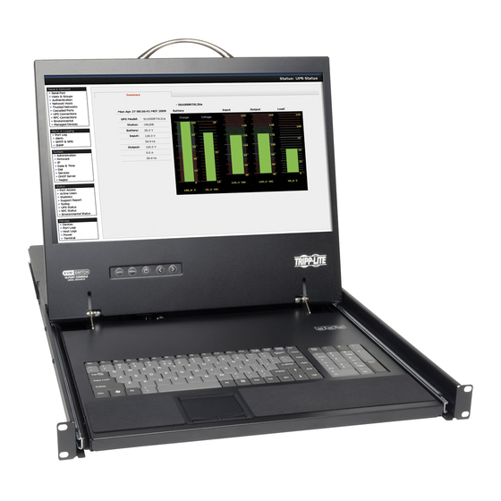
1 . Product Overview 1 .7 The NetCommander IP Unit Console KVM Switch Front View Upper Handle – Pull to slide the console out; push to slide the console in. 19” LCD Screen – After sliding the console out, flip up the cover to access the LCD screen, keyboard and touchpad. LCD Controls – The LCD On/Off button is located here, as well as buttons to control the position and picture settings of the LCD screen. Keyboard 2-Button Touchpad Rackmounting Brackets –... - Page 7 1 . Product Overview Console KVM Switch Rear View Power Outlet – The power cord included with the console connects to the unit here. Reset Button – Pressing this button for 10 seconds restores the system to its factory default settings. Serial Ports 1 and 2 – The KVM features two RJ45 serial ports for connecting serial manageable devices, such as PDUs, firewalls, and routers (see the Serial Pinout section in this manual for the pinout information).
-
Page 8: Rackmounting The Netcommander Ip
1 . Product Overview Rackmount KVM Switch Rear View The NetCommander IP back panel is illustrated in the figure below. Note: The figure below shows the back panel for a B072-016-1-IP , but the back panel will be functionally the same for all models, with the only difference being the number of server ports. Power Outlet –... -
Page 9: Connecting The System
10. Optional: Connect up to two serial devices to the RJ45 Serial Ports 1 and 2 on the back of the KVM switch (See the Configuring Serial Port Settings section of this manual for details on configuration. See the Serial Pinout section in this manual for the pinout information). 11. Connect the included power cord between the C14 outlet on the back of the unit and a Tripp Lite Surge Suppressor, Power Distribution Unit (PDU), or Uninterruptible Power Supply (UPS). There is no Power On/Off switch, so plugging in the power cord will power on the KVM. - Page 10 1 . Product Overview To set the IPv4 address via the local console OSD: From the local console, press the left [Shift] key twice to open the OSD. Press the [F2] key to open the Settings menu. In the Settings menu, press the [Tab] key until the DHCP field is highlighted.
- Page 11 1 . Product Overview Upon installing the certificate or accepting the unrecognized certificate for the current session, the initial web page appears, and the Java application is launched. Before the installation completes, a security warning may appear stating that the connection to this website is untrustworthy. This is a security issue similar to one you get from your web browser. You can choose to continue anyway, or install the certificate in the Java control panel. Refer to the Security Certificate Installation section of this manual for further instructions. After the Java application is launched, the login page appears. If the login page does not appear on its own, click the Log On button in the center of the web page to bring it up. If clicking on the Log On button does not bring up the login page, add /targets.jnlp to the end of your IP address.
- Page 12 1 . Product Overview 7. There are two LAN sections in the Device tab, one for IPv4 and one for IPv6. For IPv4, you have the options of automatically assigning an address via DHCP server (default) and manually assigning an address. For IPv6, you have the options of automatically assigning an address via DHCP server (default), automatically assigning a stateless address, manually assigning an address, or disabling IPv6 altogether. Make the desired selections, depending on how you wish the IP address to be assigned. 8. Populate the fields in the IPv4 or IPv6 sections with the desired network information. 9. Click the Save icon in the toolbar above the Configuration menu tabs to save the network settings. Upon clicking Save, you will be prompted to reboot the KVM to finish the implementation of the new Device settings. Click Yes to proceed.
-
Page 13: Web Configuration Interface
2 . Web Configuration Interface The NetCommander IP can be accessed in two ways: locally via the local console OSD, or remotely via the Web Configuration Interface. This section of the manual details the Web Configuration Interface, which can be used to access the computer/servers and other devices connected to the KVM, as well as to configure the KVM’s settings and accounts. 2 .1 Logging Into the Web Configuration Interface Note: • Before logging on the first time, verify that you have the latest Java installed on your computer (Java 1.6 or higher is required). If not, you can download and install Java from http://www.java.com/en/download/index.jsp. -
Page 14: Web Configuration Interface Layout
2 . Web Configuration Interface Enter in your username and password, and press Enter. If this is the first time you are accessing the KVM, enter in the default username (admin) and password (access). The My Targets page of the Web Configuration Interface opens, showing the state of your unit, and displaying all your available Target Servers. 2 .2 Web Configuration Interface Layout The Web Configuration Interface contains the following main elements: Element... -
Page 15: My Targets Section
2 . Web Configuration Interface 2 .3 My Targets Section The My Targets section of the Web Configuration Interface is the first page that is displayed upon logging into the KVM remotely. This section is where users remotely access the connected computers/servers and serial devices. When accessing the My Targets section, only the connected computers/servers and devices that the logged-in account has access to are displayed in the Data Pane. -
Page 16: Configuration Section
2 . Web Configuration Interface The following table describes the columns found in the My Targets section Data Pane. Server Name The Server Name column displays all of the Target Servers and Serial devices that are accessible to the logged in account. -
Page 17: Firmware Upgrade
The Device Firmware Upgrade page appears, displaying the current firmware version installed on the KVM. In the Version to upgrade with field, browse to and select the firmware upgrade file that you just downloaded from the Tripp Lite website. - Page 18 Click the Show Versions button to display the current hardware and firmware versions of the SIUs connected to the selected ports. In Upgrade File field, browse to and select the firmware upgrade file that you just downloaded from the Tripp Lite website.
-
Page 19: Backup/Restore
2 . Web Configuration Interface 2 .4 .2 Backup/Restore Using the Backup/Restore function in the Configuration sections toolbar, you can back up all configuration data and restore it at a later date. To back up data: In the toolbar, click on icon. -
Page 20: Ssl Certificate
2 . Web Configuration Interface To restore data: In the toolbar, click on icon. The Backup/Restore Data page appears. Click the Browse button next to the Restore data from file field, and then navigate to and select the KVM backup. Click the Restore button to restore the KVM configuration. -
Page 21: Device
2 . Web Configuration Interface 6. When the SSL certificate has been installed, a prompt appears to let you know the installation was successful, and that the KVM will be rebooted. Click the OK button to exit the Web Configuration Interface and reboot the KVM. 2 .4 .4 Device The Device tab in the Configuration section allows administrators to configure the KVM’s Device ID, LAN, and SNMP settings. The settings in this page are described in the following section. Configuring the Device ID settings: • Device Name –... -
Page 22: Users
2 . Web Configuration Interface • Obtain DNS Server Address Automatically – When the DHCP mode checkbox is checked, this checkbox is also checked. When the Stateless or Static mode checkboxes are checked, this checkbox is deactivated, and you must manually enter a DNS Server address. • DNS Server – When in DHCP mode, check the checkbox next to DNS Server to manually assign its address. When the Stateless or Static mode checkboxes are checked, the Obtain DNS Server Address Automatically checkbox is deactivated, and you must manually enter a DNS Server address. Enter a DNS Server address appropriate for your network. - Page 23 2 . Web Configuration Interface To add an account: Click on the Users tab in the Configuration section. The Users page opens and displays a list of existing accounts. Click the Add button. The Add User page appears. Type in a User Name and Password. The password must be at least six alphanumeric characters long and cannot include the user name, even if other characters are added.
-
Page 24: Switch Configuration
2 . Web Configuration Interface To delete a User: In the Users page, select an account from the list and click the Delete button. The Delete Selected User(s) confirmation page appears. Note: You cannot delete an Administrator who is logged onto the system. Click Yes to delete the selected account(s) from the KVM. -
Page 25: User Targets
2 . Web Configuration Interface 2 .4 .7 User Targets By default, administrators are allowed access to all servers. However, you must define the access rights of each user account to the following: • Target Access – To initiate a remote session for the corresponding port. • Virtual media access – To use the Virtual Media functionality when in a remote session for the corresponding port. To configure User Targets: From the Configuration section, select the User Targets tab. - Page 26 2 . Web Configuration Interface In PDU Name, type an appropriate name for the PDU you are adding. The Type drop-down menu provides a list of PDUs that are supported by the NetCommander IP . Select your PDU from this list. Based on your selection, the number of PDU outlets is displayed in the Outlets field. In the Address section, enter in the type of IP Address appropriate for your PDU: IPv4, IPv6, or Host. Note: When using a host name for an IPv6 address, add the prefix udp6: to it.
-
Page 27: Power Outlets
2 . Web Configuration Interface 2 .4 .9 Power Outlets Once a PDU is added to the KVM via the Power Devices section, you need to assign a NetCommander IP Target Server port to one of the ports on a PDU to be able to Power Cycle it, or turn its power Off/On. For Target Servers with dual power supplies, you can assign multiple PDU ports to the same KVM port. -
Page 28: Serial Ports
2 . Web Configuration Interface 2 .4 .10 Serial Ports The Serial Ports page is where you configure the settings of the serial device(s) that you have connected to the KVM. (See the Serial Pinout section in this manual for the pinout information.) To configure the serial port settings: From the Configuration section, select the Serial Ports tab. The Serial Ports page appears. For each serial device connected, enter an appropriate Device Name, and then set the Baud Rate, Parity, Data Bits and Stop Bits settings accordingly. - Page 29 2 . Web Configuration Interface In the Account Blocking section: • In the Block after field, enter in the number of unsuccessful login attempts that will be allowed in a given time period. This time period is set in the attempts within (hr:min) field. Enter into this field the time in hours and minutes. • In the Block account field, you can select the length of time that an account will be blocked for if it exceeds the number of unsuccessful login attempts.
-
Page 30: Authentication
2 . Web Configuration Interface 2 .4 .12 Authentication The Authentication page allows you to set up remote authentication via RADIUS and/or LDAP/S server. From the Configuration section, select the Authentication tab to open this page. Enable Authentication Methods – The section at the top of the Authentication page determines which types of authentication are enabled, and what priority they take when authenticating a user. - Page 31 2 . Web Configuration Interface • To add an LDAP/S server to the list, click on the Add button to bring up the Add LDAP Server screen. • Enter the IPv4, IPv6, or Host address for your LDAP/S server in the corresponding field. • Select the Port number that is used by the server.
- Page 32 2 . Web Configuration Interface • Search Base – The Search Base field should be populated with the location in the Active Directory in which the search is taking place. • Search Password – The Search Password field should be populated with the password for the user account that is being used to query the Active Directory. • Confirm Password –...
- Page 33 Authentication Sources section. To setup RADIUS authentication, make sure that the RADIUS tab in the Authentication Sources section is selected, and then follow the instructions below. Note: For RADIUS Authentication to work properly, a Tripp Lite dictionary must be installed on the RADIUS server.
-
Page 34: Date & Time
Access Rights Permission String section of this manual. The only difference is that it will need to contain the prefix TrippLite-KVM-ACL=, which designates the property used for it under the Tripp Lite Dictionary. -
Page 35: Events Section
2 . Web Configuration Interface In the New Password field, type in a new password, according to the Password Policy set in the Security page of the Configuration section (see the Security section in this manual for details). In the Confirm Password, retype the new password. Click . The new password is saved in the system. 2 .6 Events Section The Events section of the Web Configuration Interface allows administrator accounts to view a log of events that take place on the installation. -
Page 36: Conducting A Remote Session
3 . Conducting a Remote Session A remote session allows accounts IP access to computer/servers and serial devices connected to the KVM. In a remote session, accounts can access computers/servers, power cycle or turn power to a Target Server Off/On, virtually mount an .iso file, and configure the remote session settings. -
Page 37: Remote Session Toolbar
3 . Conducting a Remote Session 3 .2 Remote Session Toolbar The NetCommander IP provides a toolbar that allows a remote session to be manipulated. The features on the toolbar allow you to toggle between accessible ports, adjust the video settings of the remote session, align the local and remote mouse pointers, etc.. When a remote session is initiated, the toolbar is displayed briefly in the top-center of the screen, and then collapses to display only a thin bar. To expand the toolbar, simply move the mouse pointer over the blue bar at the top-center of the screen. The following sections describe the features available in the remote session toolbar, and how they are used. - Page 38 3 . Conducting a Remote Session • Unmount ISO – The Unmount ISO feature disconnects an ISO virtual media file that has already been mounted. To unmount an ISO file: Click on the icon in the remote session toolbar, and choose the Unmount ISO option. A prompt appears asking you to confirm the action.
-
Page 39: Video
3 . Conducting a Remote Session In the Exclusivity section, check the Exclusive Session checkbox to prevent other accounts from accessing the Target Server port at the same time. By default, this checkbox is unchecked, and a remote session is initiated in Share Mode, which allows up to 5 accounts to log into a port at the same time (see the Shared Session section in this manual for details). Note: Although an Exclusive Session prevents other accounts from remotely logging into a port at the same time as you, administrator accounts still have the ability to disconnect your session and access the port if desired, and a local account can access the port and disconnect your session. -
Page 40: Power
3 . Conducting a Remote Session To manually adjust the video settings: Click on the icon in the remote session toolbar, and choose the Advanced option. The Advanced window appears. In the Brightness & Contrast section of the Advanced screen, use the corresponding scales to adjust the brightness and contrast of the displayed image. -
Page 41: Keys
3 . Conducting a Remote Session 3 .2 .5 Keys – Clicking on the Keys icon will display a list of predefined key sequences (e.g. Ctrl + Alt + Delete) that can be performed on the Target Server. By default, performing these key sequences on the Client Computer’s keyboard sends the command to the Client Computer. Opening the Keys menu and clicking on one of the predefined commands will send it directly to the Target Server. In addition, the Keys feature allows you to add commands to the Keys drop-down list, and create commands that are not already provided. - Page 42 3 . Conducting a Remote Session To record a keyboard sequence: Open the Special Key Manager window and click the Record New Custom Key button. The Record New Custom Key macro screen appears. In the Label field, type a name for the new key sequence. Click the Start Recording button. 4. On your keyboard, press the keys to include in the key sequence. The names of the pressed keys appear in the provided area as you type them.
-
Page 43: Mouse
3 . Conducting a Remote Session 3 .2 .6 Mouse – Clicking on the Mouse icon allows you to select the Mouse Settings mode being used, as well as to manually adjust settings related to mouse synchronization. The following section describes the settings found via the Mouse icon and how to use them, as well as general tips for mouse synchronization and improving keyboard/mouse response time. - Page 44 3 . Conducting a Remote Session To configure settings in Relative Mouse Position, OS-Specific mode: Click on the icon in the remote session toolbar, and choose the Mouse Settings option. The Mouse Settings window appears. Check the Relative Mouse Position, OS-Specific checkbox. Additional settings appear that allow you to manually configure the mouse settings according to your Target Server’s OS and mouse type.
- Page 45 3 . Conducting a Remote Session To align the mouse pointers: Note: The Align function is only available in the Mouse drop-down menu when the Mouse Settings mode is set to Relative Mouse Position. When logging into the KVM or accessing a new port, the local and remote mouse pointers may not be aligned. This does not always mean that they are not set up properly. Click on the Align feature in the Mouse drop-down menu of the toolbar to bring them together. Click on the icon in the remote session toolbar, and choose the Align option (or press [Ctrl] + [M]). The mouse pointers align.
-
Page 46: Server/Serial
3 . Conducting a Remote Session 3 .2 .7 Server/Serial – Clicking on the Server/Serial icon displays a drop-down list of ports that are accessible to the currently logged-in account. Simply select a port to access it. 3 .2 .8 Full Screen –... -
Page 47: Local Console
4 . Local Console This chapter explains how to operate the NetCommander IP via the local console. The local console allows you to access connected computer/servers, configure the KVM’s network settings, and to configure some more basic settings specific to local access. To display the OSD: From the local keyboard, press the left Shift key twice. The OSD Main window appears. Lines with sun icons in the PM column show active computers/ servers. A computer that is connected, but is powered-off, does not have a sun icon. When a server is busy (when an account is accessing it in an Exclusive Session), the entire line appears in red characters. -
Page 48: Power Management
4 . Local Console 4 .3 Power Management As with the Web Configuration Interface, you are able to perform power management functions via the local console. The power management functions available to you are described below. Note: In order to perform power management actions on a port, it must be configured to match a power outlet of a power device that has been added to the KVM. (See the Power Device and Power Outlets sections of this manual for details) Cycle –... - Page 49 4 . Local Console To set the IPv4 address via the local console OSD: From the local console, press the left [Shift] key twice to open the OSD. Press the [F2] key to open the Settings menu. In the Settings menu, press the [Tab] key until the DHCP field is highlighted.
- Page 50 4 . Local Console Changing the Hotkey: By default, the hotkey combination used to open the OSD is [Shift] + [Shift]. You can change this hotkey in the F2 – SETTING menu to use any of the following. Note: The left [Shift] hotkey must be used; the right [Shift] key will not work. If you set the hotkey to [Ctrl] + [Ctrl] or [Ctrl] + [F11], the left [Ctrl] key must be used.
-
Page 51: Serial Port Pinout
5 . Serial Port Pinout Note: When connecting a Cisco device, use Cisco rolled cable. Serial Port 1: Serial Port 2: Pin 1: RTS Pin 1: RTS Pin 2: DTR Pin 2: DTR Pin 3: TX Pin 3: TX Pin 4: GND Pin 4: GND Pin 5: GND Pin 5: GND Pin 6: RX Pin 6: RX Pin 7: DSR (pins 7 and pin 2 are shorted inside the unit) Pin 7: DSR Pin 8: CTS Pin 8: CTS 6 . Security Certificate Installation When remotely logging in to the KVM, you may get security warnings from your Web browser and/or Java pop-up stating that the connection to the website cannot be trusted. This occurs because the KVM’s security certificate is not among the browser and/or Java control panel’s list of trusted certificates. - Page 52 6 . Security Certificate Installation 3. Click on the Certificate error message to display the Certificate Invalid prompt. 4. Click on the View certificates option at the bottom of the prompt to redirect to the Certificate screen. 14-03-051 93-32D5.indd 52 3/14/2014 9:52:43 AM...
- Page 53 6 . Security Certificate Installation 5. Click on the Install Certificate button to bring up the Certificate Import Wizard, then click the Next button. 6. Select the option to Place all certificates in the following store, then click the Browse button. Highlight the Trusted Root Certification Authorities folder.
- Page 54 6 . Security Certificate Installation Java Security The following steps apply to Internet Explorer 9 and Java version 1.7.0_45, but may also be used with other Web browsers and Java versions. Note: You may need to run Internet Explorer as an Administrator to install the security certificate. Open your Web browser and login to the KVM. If the KVM certificate has not yet been installed in the browser, a URL bar with a Certificate error message will appear. Click on the Certificate error or Security Lock icon in the toolbar to pull up the Certificate screen. Click on the View Certificates option. When the Certificate window appears, click on the Details tab.
- Page 55 6 . Security Certificate Installation In the Details tab page, click on the Copy to File button. The Certificate Export Wizard appears. Click Next, accepting the default values until you get to the File to Export page. Click the Browse button to navigate the location you want to save the certificate file, and then type a name into the File name field. Click Next to go back to the File to Export screen, where the file path will be entered.
- Page 56 6 . Security Certificate Installation Click the Next button, followed by the Finish button on the next page to complete export of the KVM certificate. 7. Navigate to your computer’s Control Panel window and open the Java Control Panel. Click on the Security tab, then click the Manage Certificates button. In the Certificate type drop-down menu at the top of the screen, select the Secure Site option.
-
Page 57: Technical Specifications
7 . Technical Specifications Specification Description Operating systems Target Server – Windows and Linux Client computer – Windows with Internet Explorer, Firefox, or Chrome browsers. Linux with Firefox or Chrome browsers. 1920 x 1080 Max Resolution (Local console monitor on B070- Series supports a max video resolution of 1366 x 768) Distance from Switch to SIUs Up to 100 ft. (30 m.) Security SSL, high grade 128-bit AES encryption Connections Ethernet – (x2) RJ45 – 10/100 Mbps Serial – (x2) RJ45 Local KVM connection (B072-Series Only) – VGA (HD15); Keyboard/Mouse (x2) USB Server – (x16) RJ45 – 116IP / (x8) RJ45-108IP Power input... -
Page 58: Video Resolution And Refresh Rates
1152x900 1280x720 1280x768 1280x960 1280x1024 1600x1200 1920x1080 1920x1200 Note: The local console monitor on the B070-008-19-IP and B070-16-19-IP supports video resolutions up to 1366 x 768. 9 . Warranty and Warranty Registration Limited Warranty TRIPP LITE warrants its products to be free from defects in materials and workmanship for a period of two (2) years (B072-008-1-IP and B072-016-1-IP) or one (1) year (B070-008-19-IP and B070-016-19-IP) from the date of initial purchase. TRIPP LITE’s obligation under this warranty is limited to repairing or replacing (at its sole option) any such defective products. To obtain service under this warranty, you must obtain a Returned Material Authorization (RMA) number from TRIPP LITE or an authorized TRIPP LITE service center. Products must be returned to TRIPP LITE or an authorized TRIPP LITE service center with transportation charges prepaid and must be accompanied by a brief description of the problem encountered and proof of date and place of purchase. This warranty does not apply to equipment which has been damaged by accident, negligence or misapplication or has been altered or modified in any way.
Need help?
Do you have a question about the NetCommander B070-008-19-IP and is the answer not in the manual?
Questions and answers