Table of Contents
Advertisement
Quick Links
2 Port VGA Extender over Cat5
ST1212T
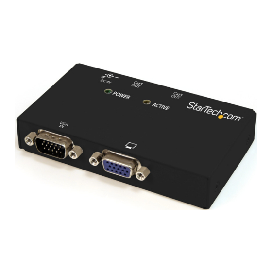
*actual product may vary from photos
DE: Bedienungsanleitung - de.startech.com
FR: Guide de l'utilisateur - fr.startech.com
ES: Guía del usuario - es.startech.com
IT: Guida per l'uso - it.startech.com
NL: Gebruiksaanwijzing - nl.startech.com
PT: Guia do usuário - pt.startech.com
For the most up-to-date information, please visit: www.startech.com
Manual Revision: 10/05/2011
Advertisement
Table of Contents

Subscribe to Our Youtube Channel
Related Manuals for StarTech.com ST1212T


Summary of Contents for StarTech.com ST1212T
- Page 1 DE: Bedienungsanleitung - de.startech.com FR: Guide de l'utilisateur - fr.startech.com ES: Guía del usuario - es.startech.com IT: Guida per l'uso - it.startech.com NL: Gebruiksaanwijzing - nl.startech.com PT: Guia do usuário - pt.startech.com For the most up-to-date information, please visit: www.startech.com Manual Revision: 10/05/2011...
- Page 2 StarTech.com. Where they occur these references are for illustrative purposes only and do not represent an endorsement of a product or service by StarTech.com, or an endorsement of the product(s) to which this manual applies by the third-party company in question. Regardless of any direct acknowledgement elsewhere in the body of this document, StarTech.com hereby...
-
Page 3: Table Of Contents
Table of Contents Introduction ....................1 Packaging Contents ..........................1 System Requirements ..........................1 View 1 ................................2 View 2 ................................2 Preparing Your Site ................3 Installation ....................4 Hardware Installation ..........................4 Driver Installation ............................5 Operation ....................5 Wiring Diagram ..................6 Specifications ..................7 Technical Support ..................8 Warranty Information ................8 Instruction Manual... -
Page 4: Introduction
Introduction The ST1212T 2 Port VGA Video Extender over Cat 5 is designed for use with our ST121 VGA over Cat 5 extension series, offering convenient VGA video distribution at distances of up to 492 feet (150 meters) using standard Cat 5 (or better) cabling. Comprised of the transmitter unit only, the ST1212T requires one Receiver Unit (ST121R) per display that you are connecting. For added versatility, the VGA over Cat 5 Repeater (ST121EXT) can be used to extend the distance between the transmitter and receiver by an additional 492-feet (150 meters), for a total distance of 984-feet (300 meters). Similarly, up to 3 repeater units can be used between transmitter and receiver, enabling you to connect monitors at each repeater, while still extending the total distance. Packaging Contents • 1 x VGA over Cat5 Video Transmitter • 1 x Set of rubber feet • 1 x Universal Power Adapter (NA/UK/EU) • 1 x Instruction Manual System Requirements • VGA enabled video source device (e.g. computer, PVR/DVR, etc.) • VGA enabled display device (e.g. monitor, projector, HDTV, etc.) • VGA cabling to connect video source and display(s) • VGA over Cat5 Receiver module - StarTech.com ID: ST121R (sold separately) • Available AC electrical outlet at transmitter and receiver locations Instruction Manual... -
Page 5: View 1
View 1 Power LED Active LED VGA connector (input) VGA connector (output) View 2 RJ45 connectors (output) DC Power connector Instruction Manual... -
Page 6: Preparing Your Site
Preparing Your Site 1. Determine where the local video source (i.e. computer, PVR/DVR) will be located and physically set up the video source device. 2. Determine where the remote display(s) will be located and place/mount the display(s) appropriately. Please note that both extender units (transmitter/receiver) will require a power connection, so please ensure that each unit will be situated near an available electrical outlet. 3. If you are using surface cabling, ensure you have enough Cat5 unshielded twisted pair (UTP) Ethernet cabling to connect the Transmitter Unit to the Receiver Unit’s location, and that each end is terminated with a RJ45 Ethernet connector. The cabling should not go through any networking equipment (i.e. router, switch). If you are using premise cabling, ensure that the Cat5 unshielded twisted pair (UTP) Ethernet Cabling between the Transmitter Unit and the Receiver Unit has been properly terminated in a wall outlet/panel in each location and there is a patch cable long enough to connect the Receiver Unit and the Transmitter Unit to their respective outlets. The cabling should not go through any networking equipment (i.e. router, switch). Instruction Manual... -
Page 7: Installation
Improper grounding may result in signal noise or potential damage to the extender units. Hardware Installation ST1212T ST121R 1. Turn off the video source (i.e. computer) and the intended display devices (i.e. monitors). 2. Position the ST121R Receiver Unit(s) (sold separately) near the intended remote display(s). OPTIONAL: with the optional mounting brackets (StarTech.com ID: ST121MOUNT), any ST121 series receiver can be securely mounted to a wall or other surface. *installation photos are for reference only 3. Position the ST1212T Transmitter Unit near the video source. 4. Connect the video source to the “Input” male VGA connector on the Transmitter Unit, using a standard VGA male/female cable. A local display can be connected to the “Monitor Out” VGA connector on the Transmitter Unit. Instruction Manual... -
Page 8: Driver Installation
5. Connect the remote display(s) to the “Monitor Out” ports located on the Receiver Unit using a VGA male/male cable. Each Receiver Unit supports two mirrored (identical) VGA outputs. 6. Connect the Transmitter Unit to each Receiver Unit, using standard RJ45 terminated Cat5 cable (see “Preparing Your Site”). OPTIONAL: If using the ST121EXT Extender Unit(s), the distance between the Transmitter and Receiver units can be extended by up to an additional 150m / 492ft. The ST121EXT also supports 2 VGA outputs and requires an AC electrical outlet. 7. Connect the power adapters (provided) to both Transmitter and Receiver Units. 8. Turn on the display device first, followed by the video source. Driver Installation No driver or software installation is required on the video source device. Operation The ST1212T provides LED indicators, allowing simple operating status monitoring. Once the power adapter has been connected, the Power LED will become illuminated; similarly, when the unit is in use (i.e. transmitting a video signal), the Active LED will become illuminated. Instruction Manual... -
Page 9: Wiring Diagram
Wiring Diagram The UTP cable must be wired according to the EIA/TIA 568B industry standard as shown below. Wire Color Pair White/Orange Orange White/Green Blue White/Blue Green White/Brown Brown Instruction Manual... -
Page 10: Specifications
Specifications Video Signal VGA (RGBHV) 1 x DE-15 VGA female 1 x DE-15 VGA male External Connectors 2 x RJ45 Ethernet female 1 x DC Power 1 x Power LEDs 1 x Active/Link 1600 x 1200 @ 50m / 150ft Supported Video Resolutions 1280 x 1024 @ 100m / 300ft 1024 x 768 @ 150m / 492ft Maximum Cable Length 150m / 492ft @ 1024 x 768 Power Adapter 9V~12V DC, 600 mA, center positive Enclosure Material Metal Operating Temperature 0°C ~ 40°C (32°F ~ 104°F) Storage Temperature -10°C ~ 60°C (14°F ~ 140°F) Humidity 0% ~ 80% RH Dimensions 102.0mm x 60.0mm x 20.0mm Weight 200g Instruction Manual... -
Page 11: Technical Support
Limitation of Liability In no event shall the liability of StarTech.com Ltd. and StarTech.com USA LLP (or their officers, directors, employees or agents) for any damages (whether direct or indirect, special, punitive, incidental, consequential, or otherwise), loss of profits, loss of business, or any pecuniary loss, arising out of or related to the use of the product exceed the actual price paid for the product. - Page 12 We make it easy to locate the parts, and we quickly deliver them wherever they need to go. Just talk to one of our tech advisors or visit our website. You’ll be connected to the products you need in no time. Visit www.startech.com for complete information on all StarTech.com products and to access exclusive resources and time-saving tools. StarTech.com is an ISO 9001 Registered manufacturer of connectivity and technology parts. StarTech.com was founded in 1985 and has operations in the United States, Canada, the United Kingdom and Taiwan servicing a worldwide market.
Need help?
Do you have a question about the ST1212T and is the answer not in the manual?
Questions and answers