Table of Contents
Advertisement
Effective : October, 2004
SERVICE MANUAL
C C R R - - H H 2 2 2 2 0 0
CONTENTS
PC boards shown are viewed from parts side.
The parts with no reference number or no parts number in the
exploded views are not supplied.
As regards the resistors and capacitors, refer to the circuit diagrams
contained in this manual.
Parts marked with this sign are safety critical components. They
£
must be replaced with identical components - refer to the appropriate
parts list and ensure exact replacement.
Parts of [ ] mark can be used only with the version designated.
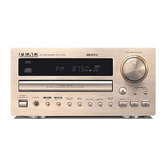
CD Receiver
NOTES
S-0129A
2
3
5
8
12
Advertisement
Table of Contents

Related Manuals for Teac CR-H220


Summary of Contents for Teac CR-H220
- Page 1 SERVICE MANUAL C C R R - - H H 2 2 2 2 0 0 CD Receiver CONTENTS 1 SPECIFICATIONS 2 MICROCOMPUTER PIN FUNCTIONS 3 EXPLODED VIEWS AND PARTS LIST 4 PC BOARDS AND PARTS LIST 5 INCLUDED ACCESSORIES NOTES PC boards shown are viewed from parts side.
-
Page 2: Specifications
1 SPECIFICATIONS AMPLIFIER Section Output Power ......25 W/ch (6 ohms, 0.5 %,1 kHz) Input Sensitivity..........300 mV/47k ohms Frequency Response ...... 20 Hz to 60,000 Hz (+1/-3 dB) TUNER Section FM Section Frequency Range ..87.50 MHz to 108.00 MHz (50 kHz steps) Signal-to-Noise Ratio .......... -
Page 3: Microcomputer Pin Functions
2 MICROCOMPUTER PIN FUNCTIONS TMP87PS71AF PIN No. NAME DESCRIPTION F_MUTE Function Mute Control port (Active "H") REMOTE Remote Data input port RDS_CLK RDS Clock input port RDS_DATA RDS Data input port TAPE(H) TAPE Control port (Active "H") AUX2(H) AUX2 Control port (Active "H") No Connection CD_STBY CD_STANDBY On Control port... - Page 4 PIN No. NAME DESCRIPTION CD_BUS0 CD_BUS1 CD_BUS Interface port CD_BUS2 CD_BUS3 CD_OPEN_SW CD Open Switch input port CD_CLOSE_SW CD Close Switch input port CD_LIMIT_SW CD Limit Switch input port TUNED_IN Tuner Module Tuned port STEREO_IN Tuner Module Stereo port No Connection POWER_H Power on port PLL_DIN...
-
Page 5: Exploded Views And Parts List
3 EXPLODED VIEWS AND PARTS LIST... - Page 6 EXPLODED VIEW LIST £...
- Page 7 EXPLODED VIEW LIST £ £ £ £...
-
Page 8: Pc Boards And Parts List
4 PC BOARDS AND PARTS LIST MAIN PCB... - Page 9 POWER PCB...
- Page 10 CD PCB ASSY MAIN PCB ASSY (GATHER) £ MAIN PCB ASSY (GATHER)
- Page 11 POWER PCB ASSY (GATHER) POWER PCB ASSY (GATHER) £ £ £ £ £ £ £ £ £ £ £ £ £ £ £ £ £ £ £ £ £ £ £ £ £ £ £ £ £ £ £ £ £...
-
Page 12: Included Accessories
5 INCLUDED ACCESSORIES INCLUDED ACCESSORIES... - Page 13 CR-H220 BLOCK DIAGRAM C C R R - - H H 2 2 2 2 0 0 CD Receiver 1 st Issue; September 2004...
- Page 14 CR-H220 WIRING DIAGRAM C C R R - - H H 2 2 2 2 0 0 CD Receiver 1 st Issue; September 2004...
- Page 15 CR-H220 SCHEMATIC DIAGRAM INPUT NOTES: 1. Resistor values are in ohms (k=kilo-ohms, M=megohms). 2. Capacitor values are in microfarads (p=picofarads). 3. £Parts marked with this sign are safety critical components. They must always be replaced with identical components-refer to the appropriate parts list and ensure exact replacement.
- Page 16 CR-H220 SCHEMATIC DIAGRAM MICOM C C R R - - H H 2 2 2 2 0 0 NOTES: 1. Resistor values are in ohms (k=kilo-ohms, M=megohms). 2. Capacitor values are in microfarads (p=picofarads). 3. £Parts marked with this sign are safety critical components.
- Page 17 CR-H220 SCHEMATIC DIAGRAM FRONT, H/P C C R R - - H H 2 2 2 2 0 0 NOTES: 1. Resistor values are in ohms (k=kilo-ohms, M=megohms). 2. Capacitor values are in microfarads (p=picofarads). 3. £Parts marked with this sign are safety critical components.
- Page 18 CR-H220 SCHEMATIC DIAGRAM AMP, SPEAKER C C R R - - H H 2 2 2 2 0 0 NOTES: 1. Resistor values are in ohms (k=kilo-ohms, M=megohms). 2. Capacitor values are in microfarads (p=picofarads). 3. £Parts marked with this sign are safety critical components.
- Page 19 CR-H220 SCHEMATIC DIAGRAM POWER C C R R - - H H 2 2 2 2 0 0 NOTES: 1. Resistor values are in ohms (k=kilo-ohms, M=megohms). 2. Capacitor values are in microfarads (p=picofarads). 3. £Parts marked with this sign are safety critical components.
Need help?
Do you have a question about the CR-H220 and is the answer not in the manual?
Questions and answers