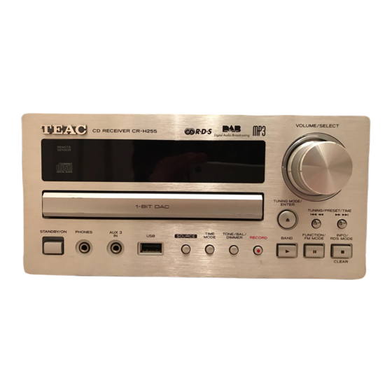
Advertisement
Effective : October, 2004
SERVICE MANUAL
C C R R - - H H 2 2 5 5 0 0
CONTENTS
PC boards shown are viewed from parts side.
●
The parts with no reference number or no parts number in the
●
exploded views are not supplied.
As regards the resistors and capacitors, refer to the circuit diagrams
●
contained in this manual.
Parts marked with this sign are safety critical components. They
£
●
must be replaced with identical components - refer to the appropriate
parts list and ensure exact replacement.
CD Receiver
For U.K.
・ ・ ・ ・ ・ ・ ・ ・ ・ ・ ・ ・ ・ ・ ・ ・ ・ ・ ・ ・ ・ ・ ・ ・ ・ ・ ・ ・ ・ ・ ・ ・ ・ ・ ・ ・ ・ ・
・ ・ ・ ・ ・ ・ ・ ・ ・ ・ ・ ・ ・ ・ ・ ・ ・
・ ・ ・ ・ ・ ・ ・ ・ ・ ・ ・ ・ ・ ・ ・
・ ・ ・ ・ ・ ・ ・ ・ ・ ・ ・ ・ ・ ・ ・ ・ ・ ・ ・ ・ ・ ・
・ ・ ・ ・ ・ ・ ・ ・ ・ ・ ・ ・ ・ ・ ・ ・ ・ ・ ・ ・ ・ ・ ・ ・ ・ ・ ・
NOTES
2
3
11
13
17
S-0130A
Advertisement

Summary of Contents for Teac CR-H250
-
Page 1: Table Of Contents
SERVICE MANUAL C C R R - - H H 2 2 5 5 0 0 CD Receiver For U.K. CONTENTS 1 SPECIFICATIONS ・ ・ ・ ・ ・ ・ ・ ・ ・ ・ ・ ・ ・ ・ ・ ・ ・ ・ ・ ・ ・ ・ ・ ・ ・ ・ ・ ・ ・ ・ ・ ・ ・ ・ ・ ・ ・ ・ 2 MICROCOMPUTER PIN FUNCTIONS ・... -
Page 2: Specifications
1 SPECIFICATIONS AMPLIFIER Section Standard Accessories Output Power ......25 W/ch (6 ohms, 0.5 %,1 kHz) Remote Control Unit (RC-956) x 1 Input Sensitivity..........300 mV/47k ohms Batteries (AAA) x 2 Frequency Response ...... 20 Hz to 60,000 Hz (+1/-3 dB) AM Loop Antenna x 1 FM Lead-type Antenna x 1 DAB Antenna x 1... -
Page 3: Microcomputer Pin Functions
2 MICROCOMPUTER PIN FUNCTIONS ST92F124V1 ■ PIN ASSIGNMENT 100 99 98 97 96 95 94 93 92 91 90 89 88 87 86 85 84 83 82 81 80 79 78 77 76 A20/P9.6 P8.4/AIN4 A21/P9.7 P8.3/AIN3 WAIT/WKUP5/P5.0 P8.2/AIN2 WKUP6/WDOUT/P5.1 P8.1/AIN1/WKUP15 SIN/WKUP2/P5.2 P8.0/AIN0/WKUP14... - Page 4 ■ BLOCK DIAGRAM FLASH Ext. MEM. 128 Kbytes A[7:0] ADDRESS D[7:0] DATA Port0 3 TM 1 Kbyte Ext. MEM. A[10:8] ADDRESS A[21:11] Ports 4 Kbytes P0[7:0] P1[7:3] P1[2:0] Fully 256 bytes P2[7:0] WAIT Prog. Register File P3[7:4] I/Os P3[3:1] 8/16 bits P4[7:4] P4[3:0] P5[7:0]...
- Page 5 ■ PIN FUNCTIONS PIN No PIN Name Function FIP Driver(IC42) Chip enable Port SM_CE VFD Control Port VFD_BLK DAB_DIN DAB Data Input Port DAB Data Clock Port DAB_CLK DAB Data Output Port DAB_DOUT No Connection No Connection Stanby LED On Control Port (Active "H") STANBY Function Mute Port (Active "H") F_MUTE...
- Page 6 PIN No PIN Name Function VTEST CD_OPEN_M Open Motor control port CD Control Interface CD_RW CD DSP IC Chip enable port (Active "L") CD_CCE CD DSP IC Clock port CD_BUCK No Connection No Connection CD Reset output port (Active "L") CD_RESET CD_POWER CD Power control port...
- Page 7 PIN No PIN Name Function PLL/FUNCTION Data Input port P/F_DATA PLL/FUNCTION Clock Input port P/F_CLK PLL Data input port PLL_DIN PLL Chip enable port PLL_CE TUNED_IN Tuner Module Tuned control port Tuner Module Stereo control port STEREO_IN RDS Data input port RDS_DATA VSS5 Power Supply port...
- Page 8 S3F84BB ■ PIN ASSIGNMENT P2.7/TAOUT P8.0 P2.6/TACAP P8.1 P2.5/TACK P8.2 P2.4/TBPWM P8.3 P2.3/DAOUT P8.4/INT8 P2.2/SCK P8.5/INT9 P2.1/SI P6.0 P2.0/SO P6.1 P5.7 P6.2 P5.6/SDAT P6.3 P5.5/SCLK P6.4 VDD1 VDD2 S3C84BB/F84BB VSS1 VSS2 (80-QFP-1420C) XOUT P6.5 P6.6 TEST P6.7 P5.4 P7.0/ADC0 P5.3/RxD0 P7.1/ADC1 RESETB P7.2/ADC2...
- Page 9 ■ BLOCK DIAGRAM P0.0-P0.7 P1.0-P1.7 Port 0 Port 1 OSC/RESETB Port 2 P2.0-P2.7 RESETB I/O Port and Interrupt Control 8-Bit Basic Timer P2.7/TAOUT 8-Bit P2.6/TACAP Port 3 P3.0-P3.7 Timer P2.5/TACK /CounterA,B P2.4/TBOUT SAM88RC CPU 8-Bit P3.7/TCOUT0 Timer/ P3.6/TCOUT1 CounterC0,C1 P4.0-P4.7/ Port 4 INT0~INT7 P3.4/T1OUT0...
- Page 10 ■ PIN FUNCTIONS PIN No. NAME DESCRIPTION VFD_CS VFD STB port VFD_CLK VFD Clock port VFD_DATA VFD data port DATA UPDATE data port UPDATE clock port VDD 1 Power input port VSS 1 X OUT 10MHz Crystal Connection port X IN TEST Pull - down register connected internally VFD_RESET...
-
Page 11: Exploded Views And Parts List
3 EXPLODED VIEWS AND PARTS LIST −11−... - Page 12 EXPLODED VIEW LIST REF.NO. PARTS NO. DESCRIPTION REMARKS CGR1A345M7ZG5 ORNAMENT,DOOR CGU1A347Z WINDOW,FIP KGB1A047Z BADGE,TEAC CGK1A098YA VOLUME KNOB ASSY CGR1A346MBC22 ORNAMENT,RING CKM1A144YC35 PANEL,FRONT CGL1A133 INDICATOR,STAND BY CGW1A386M7ZG5 PANEL,SUB CBT1A495M7G5 CAP,STAND BY CBT1A483 KNOB,STAND BY CBT1A493MBC22 KNOB,CPS CBT1A942M7G5 KNOB,MODE CBT1A943M7ZG5 KNOB,PLAY HFLHCA-17SM02T...
-
Page 13: Pc Boards And Parts List
4 PC BOARDS AND PARTS LIST MAIN PCB −13−... - Page 14 POWER PCB −14−...
- Page 15 CD PCB ASSY MAIN PCB ASSY (GATHER) REF.NO. PARTS NO. DESCRIPTION REF.NO. PARTS NO. DESCRIPTION COP11767C PCB,CD ASSY IC51 HVILC75343M IC,LC75343M CUP11767Z PCB,CD IC52 HVITC9163AF IC,TC9163AF CN10 KJP05GA19ZM WAFER,MOLEX53014-0510 IC53 HVINJM2068MDTE1 IC,NJM2068MD-TE1 CN11 KJP06GA19ZM WAFER,MOLEX53014-0610 JK21 CJJ4M046Z JACK,BOARD CN12 KJP16GB113ZG WAFER,16P JK22 CJJ4P014W...
- Page 16 POWER PCB ASSY (GATHER) POWER PCB ASSY (GATHER) REF.NO. PARTS NO. DESCRIPTION REF.NO. PARTS NO. DESCRIPTION COP11720B PCB,POWER ASSY ET91 CNE75 PLATE,EARTH CUP11720Y PCB,POWER F751 KJCFC5S HOLDER,FUSE CMC1A253 PLATE,EARTH IC21 BVI74HC4066D IC,74HC4066D CMH1A226 SUPPORT,PCB IC22 BVISTK442-050 IC,STK442-050 HNVFS2020VENICE DAB MODULE,FS2020VENICE1.1 IC91 CMY1A043 HEAT SINK...
-
Page 17: Included Accessories
5 INCLUDED ACCESSORIES INCLUDED ACCESSORIES REF.NO. PARTS NO. DESCRIPTION REMARKS CQX1A941Z OWNER'S MANUAL CARTCRH250 REMOCON TRANSMITTER ASSY HABAAAM1.5V BATTERY CSA1A018Z FM 1 POLE ANT CSA1A020Z AM LOOP ANT CSA272 ANT,DAB T −17−...


Need help?
Do you have a question about the CR-H250 and is the answer not in the manual?
Questions and answers