Fluke 110 Calibration Information Manual
Hide thumbs
Also See for 110:
- User manual ,
- Calibration information manual (26 pages) ,
- User manual (18 pages)
Table of Contents
Advertisement
Introduction
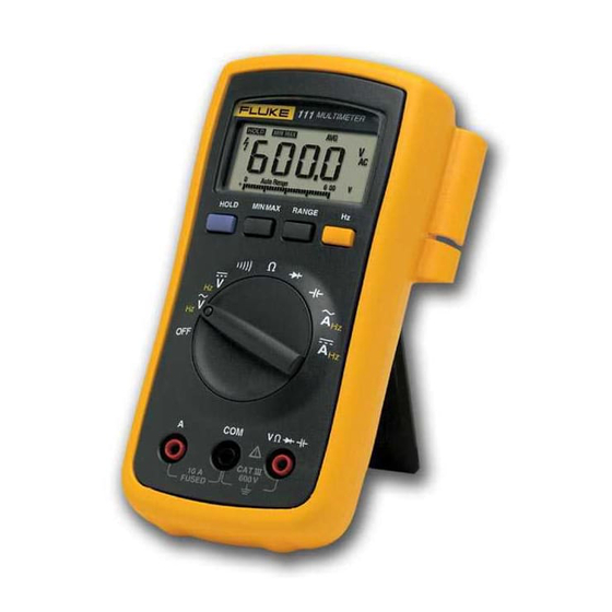
The Fluke Model 110, Model 111, and Model 112 True RMS multimeters (hereafter "the Meter") are
battery-powered, with a 6000-count display and a bar graph.
This calibration information applies to all three models. All figures show the Model 112.
The Meter measures or tests the following:
AC and DC voltage
Resistance
Continuity
Diodes
Frequency
Capacitance
AC and DC current (Model 111 and Model 112)
"Warning" and "Caution" Statements
A "WWarning" statement identifies hazardous conditions and actions that could cause bodily harm or
death.
A "Caution" statement identifies conditions and actions that could damage the Meter or the equipment
under test.
Unsafe Voltage Symbol
To alert you to the presence of a potentially hazardous voltage, the Y symbol is displayed when the Meter
detects a voltage
30 V or a voltage overload (OL) condition.
Test Lead Alert
Personal injury or damage to the Meter can occur if you attempt to make a
measurement with a lead in an incorrect terminal.
To remind you to check that the test leads are in the correct terminals,
move the rotary switch to or from any A position.
These Meters meet CAT III IEC 61010-1-95 standards. The IEC 61010-1-95 safety standard defines four
overvoltage categories (CAT I to IV) based on the magnitude of danger from transient impulses. CAT III
meters are designed to protect against transients in fixed-equipment installations at the distribution level.
1608592
PN
March 2001
©2001 Fluke Corporation. All rights reserved. Printed in U.S.A.
Models 110, 111 & 112
Calibration Information
WWarning
Multimeters
is displayed briefly when you
®
1
Advertisement
Table of Contents

Related Manuals for Fluke 110


Summary of Contents for Fluke 110
-
Page 1: Calibration Information
Calibration Information Introduction The Fluke Model 110, Model 111, and Model 112 True RMS multimeters (hereafter "the Meter") are battery-powered, with a 6000-count display and a bar graph. This calibration information applies to all three models. All figures show the Model 112. -
Page 2: Table Of Contents
The information provided in this manual is for the use of qualified personnel only. This document provides the information necessary to calibrate and verify the performance of the Fluke Model 110, 111, and 112 multimeters. The following information is included:... -
Page 3: Safety Information
Safety Information Safety Information WWarnings and Precautions To avoid possible electric shock or personal injury, follow these guidelines: Use the Meter only as specified in this manual or the protection provided by the Meter might be impaired. Do not use the Meter or test leads if they appear damaged, or if the Meter is not operating properly. -
Page 4: Models 110
Models 110, 111 & 112 Calibration Information Specifications Accuracy is specified for 1 year after calibration, at operating temperatures of 18 C to 28 C (64 F to 82 F), with relative humidity at 0 % to 95 %. The accuracy specifications take the form of:... -
Page 5: Specifications
Specifications Specifications (continued) Accuracy ± ( [ % of Reading ] + [ Counts ] ) Function Range Resolution Model 110 Model 111 Model 112 Diode test 2.200 V 0.001 V 0.9 % + 2 Capacitance 1000 nF 1 nF 1.9 % + 2... -
Page 6: Testing The Fuse
Models 110, 111 & 112 Calibration Information Testing the Fuse (Models 111 and 112) WWarning To avoid electrical shock or injury, remove the test leads and any input signals before replacing the fuse. Test the fuse as shown below. <.5 aej12f.wmf... -
Page 7: Replacing The Battery And Fuse
Replacing the Battery and Fuse Replacing the Battery and Fuse WWarning To avoid electric shock, injury, or damage to the Meter: Remove test leads from the Meter before opening the case or battery door. Use ONLY a fuse with the amperage, interrupt, voltage, and speed ratings specified. - Page 8 Models 110, 111 & 112 Calibration Information To replace the fuse (Models 111 and 112) Turn the rotary switch to and remove the test leads from the terminals. Remove the Meter from the protective yellow holster. Remove the battery and battery door.
-
Page 9: Replacing The Lcd
Replacing the LCD Replacing the LCD You must remove the circuit board assembly to access and replace the LCD. Caution The circuit board is extremely susceptible to contamination. To avoid contamination, handle it by the input receptacle, fuse clips, or edges of the board only. -
Page 10: Performance Tests
Models 110, 111 & 112 Calibration Information LCD mask aej18f.wmf Figure 5. Removing the LCD Mask 8. Reattach the LCD mask by pressing it over the LCD until it snaps into place. 9. Place the PCA into the case top with the LCD showing through the window and snap the PCA into place. - Page 11 Performance Tests Required Equipment A Fluke 5500A Multi-Product Calibrator (or equivalent) is required for the performance test procedures in this document. If an equivalent calibrator is used, it must meet the accuracy specifications shown in Table 1. Table 1. Calibrator Specifications...
-
Page 12: Performance Tests
Models 110, 111 & 112 Calibration Information Table 2. Performance Test Steps Function Frequency Display (switch position) Input value (sine wave) Lower Limit Upper Limit 300 mV 50 Hz 0.294 0.306 300 mV 500 Hz 0.294 0.306 50 Hz 4.947 5.053... -
Page 13: Calibrating The Meter
Calibrating the Meter Calibrating the Meter To enable Calibration mode 1. Turn the rotary switch to the position. 2. Using a small blunt probe, press and hold the recessed calibration button for one second. The recessed calibration button is located under the calibration seal on the back of the Meter. The Meter beeps once and then enters Calibration mode. -
Page 14: Display Messages
- Hz C-02 6.000 V 60 Hz C-03 6.000 V 600 e C-04 C-05 6.000 ke Table 5. Calibration Settings for the Fluke 111 and 112 Step Function Frequency Seconds Number (switch position Input value (sine wave) to Settle C-01 6.000 V... -
Page 15: Cleaning The Meter
Cleaning the Meter Cleaning the Meter WWarning To avoid electrical shock or damage to the Meter, never allow water inside the case. To avoid damaging the housing, never apply solvents to the Meter. Periodically wipe the case with a damp cloth and mild detergent. Do not use abrasives or solvents. Dirt or moisture in the input terminals can distort meter readings. -
Page 16: User-Replaceable Parts
Models 110, 111 & 112 Calibration Information User-Replaceable Parts User-replaceable parts are shown in Table 6. Table 6. User Replaceable Parts aej16f.wmf Item Description Part No Holster 1579321 Tilt stand 1566954 Battery door 1572523 9 V Alkaline battery, ANSI 1604A/IEC 6LR61...