
Related Manuals for Fluke 116C


Summary of Contents for Fluke 116C
- Page 1 ® 116C True-rms Multimeter Users Manual PN 2538707 July 2006, Rev. 1, 2/07 © 2006, 2007 Fluke Corporation. All rights reserved. Printed in China All product names are trademarks of their respective companies.
-
Page 2: Limited Warranty And Limitation Of Liability
LIMITED WARRANTY AND LIMITATION OF LIABILITY This Fluke product will be free from defects in material and workmanship for three years from the date of purchase. This warranty does not cover fuses, disposable bat- teries, or damage from accident, neglect, misuse, alteration, contamination, or abnor- mal conditions of operation or handling. -
Page 3: True-Rms Multimeter
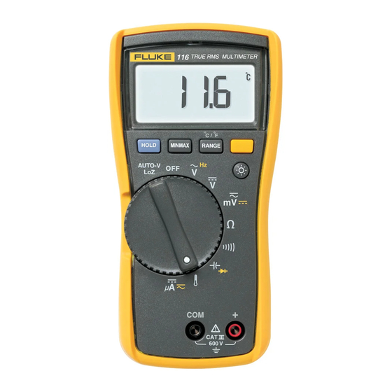
True-rms Multimeter Introduction Contacting Fluke The Fluke Model 116C, is a battery-powered, true-rms To contact Fluke, call: multimeter (hereafter "the Meter") with a 6000-count USA: 1-888-99-FLUKE (1-888-993-5853) display and a bar graph. China: 010-65123435 This meter meets CAT III IEC 61010-1 2... - Page 4 116C Users Manual Safety Information A "XWWarning" statement identifies hazardous conditions and actions that could cause bodily harm or death. A "WCaution" statement identifies conditions and actions that could damage the Meter or the equipment under test. To avoid possible electric shock or personal injury, follow these guidelines: Use the Meter only as specified in this manual or the protection provided by the Meter might be impaired.
-
Page 5: Safety Information
Battery (Low battery when shown on display.) DC (Direct Current) Double Insulated Hazardous voltage Important Information; Refer to manual AC and DC Earth ground Do not dispose of this product as unsorted municipal waste. Contact Fluke or a qualified recycler for disposal. - Page 6 116C Users Manual Display eeo02f.eps Symbol Meaning The Meter function is set to Continuity. The Meter function is set to Diode Test Input is a negative value. X Unsafe voltage. Measured input voltage 30 V, or voltage overload condition (OL). Display hold enabled.
- Page 7 True-rms Multimeter Display Symbol Meaning MIN MAX AVG mode enabled. Maximum, minimum, average or present reading displayed The Meter is measuring voltage or capacitiance with a low input impedance. nµ°F°C mVµA Measurement units. DC AC Direct current or alternating current Battery low warning.
-
Page 8: Terminals
116C Users Manual Terminals edy01f.eps Description Common (return) terminal for all measurements. Input terminal for measuring voltage, continuity, resistance, capacitance, frequency, temperature, microamps and testing diodes.. Error Messages bAtt Battery must be replaced before the Meter will operate. CAL Err Calibration required. -
Page 9: Rotary Switch Positions
True-rms Multimeter Rotary Switch Positions Rotary Switch Positions Switch Position Measurement Function Automatically selects ac or dc volts based on the sensed input with a low impedance input. AC voltage from 0.06 to 600 V. Frequency from 5 Hz to 50 kHz. Hz (button) DC voltage from 0.001 V to 600 V. - Page 10 116C Users Manual Battery Saver ("Sleep Mode") Display HOLD XWWarning The Meter automatically enters "Sleep mode" and blanks the display if there is no function change, range change or To avoid electric shock, when Display button press for 20 minutes. Pressing any button or HOLD is activated, be aware that the turning the rotary switch awakens the Meter.
-
Page 11: Power-Up Options
True-rms Multimeter Power-Up Options When you turn the Meter on, it defaults to Autorange and Power-Up Options are canceled when you turn the Meter Auto is displayed. off and when sleep mode is activated. 1. To enter the Manual Range mode, press q. Button Power-Up Options Manual is displayed. - Page 12 116C Users Manual Measuring Resistance Testing for Continuity eeo06f.eps eeo04f.eps XWWarning Note To avoid electric shock, injury, or The continuity function works best as a fast, damage to the Meter, disconnect convenient method to check for opens and circuit power and discharge all high- shorts.
-
Page 13: Making Basic Measurements
True-rms Multimeter Making Basic Measurements Measuring AC and DC Voltage Measuring AC and DC Millivolts Volts AC Volts DC Millivolts AC Millivolts DC edy18f.eps eeo03f.eps Using Auto Volts Selection With the function switch in the l position, the Meter measures ac plus dc millivolts. Press g to switch the With the function switch in the x position, the Meter automatically selects a dc or ac voltage measurement Meter to dc millivolts. - Page 14 116C Users Manual Measuring AC and DC Current WWarning To avoid personal injury or damage to the Meter: Never attempt to make an in-circuit current measurement when the open- Flame circuit potential to earth is 600 V. sensor Use the proper switch position and range probe for your measurement.
- Page 15 True-rms Multimeter Making Basic Measurements Measuring Capacitance Measuring Temperature RANGE Vent 80BK Type K Pipe Thermocouple Probe eeo10f.eps XW Warning eeo05f.eps To avoid risk of electric shock, do NOT connect 80BK to live circuits.
- Page 16 116C Users Manual Measuring Frequency The Meter measures the frequency of a signal by counting the number of times the signal crosses a trigger level each XWWarning second. The trigger level is 0 V for all ranges. To avoid electrical shock, disregard 1.
-
Page 17: Making Low Impedance Capacitance Measurements
Meter. Make sure the Meter has the correct function, AC or DC, selected for your current probe. Refer to a Fluke catalog or contact your local Fluke representative for compatible current clamps. Single... - Page 18 116C Users Manual Using the Bargraph Maintenance The bar graph is like the needle on an analog meter. It has Maintenance of the Meter consists of replacing the battery an overload indicator (>) to the right and a polarity and cleaning the case. indicator (+)to the left.
- Page 19 True-rms Multimeter Cleaning XWWarning The battery fits inside the battery door, which is then inserted into the case, bottom edge first, until it is fully To avoid shock, injury, or damage to seated. Do not attempt to install the battery directly into the the Meter, remove test leads from the case.
- Page 20 Accuracy is specified for 1 year after calibration, at operating temperatures of 18 C to 28 C, with relative humidity at 0 % to 90 %. Extended specifications are available at www.Fluke.com. Maximum voltage between any terminal and earth ground......600 V Surge Protection .........
-
Page 21: General Specifications
True-rms Multimeter General Specifications IP Rating (dust and water protection) .... IP42 Table 1. Accuracy Specifications Accuracy Function Range Resolution ([% of Reading] + [Counts]) DC millivolts 600.0 mV 0.1 mV 0.5 % + 2 6.000 V 0.001 V DC Volts 60.00 V 0.01 V 0.5 % + 2... - Page 22 116C Users Manual Table 1 Accuracy Specifications (cont.) Accuracy Function Range Resolution ([% of Reading] + [Counts]) Beeper on < 20 , off > 250 Continuity detects opens or shorts of 500 s or longer. 600.0 0.9 % + 2 6.000 k 0.001 k 0.9 % + 1...
- Page 23 True-rms Multimeter General Specifications Table 1 Accuracy Specifications (cont.) Accuracy Function Range Resolution ([% of Reading] + [Counts]) AC Amps True-rms 1.5 % + 3 600.0 A 0.1 A (45 Hz to 1 kHz) (2.5 % + 3 >500 Hz) DC Amps 600.0 A 0.1 A...
- Page 24 116C Users Manual Table 2. Input Characteristics Input Impedance Common Mode Rejection Ratio Normal Mode Function (Nominal) (1 k Unbalanced) Rejection Volts AC >5 M <100 pF >60 dB at dc, 50 or 60 Hz >10 M <100 pF >100 dB at dc, 50 or 60 Hz >60 dB at 50 or 60 Volts DC Auto-V LoZ...
Need help?
Do you have a question about the 116C and is the answer not in the manual?
Questions and answers