
Related Manuals for Sierra Wireless AirLink FXT Series


Summary of Contents for Sierra Wireless AirLink FXT Series
- Page 1 Fastrack Xtend User Guide AirLink FXT Series WA_DEV_FEX20_UGD_002 April 26, 2010...
-
Page 2: Rev
Data may be delayed, corrupted (i.e., have errors) or be totally lost. Although significant delays or losses of data are rare when wireless devices such as the Sierra Wireless modem are used in a normal manner with a well-constructed network, the Sierra Wireless modem should not be used in situations where failure to transmit or receive data could result in damage of any kind to the user or any other party, including but not limited to personal injury, death, or loss of property. -
Page 3: Contact Information
D560,911 and other patents pending. ® This product includes technology licensed from QUALCOMM Manufactured or sold by Sierra Wireless or its licensees under one or more patents licensed from InterDigital Group. Copyright © 2010 Sierra Wireless. All rights reserved. Trademarks ®... -
Page 4: Document History
Wireless CPU to Intelligent Embedded Module/embedded module ® Open AT Software Suite to Sierra Wireless Software Suite Updated Table 65: Power Consumption of FXT003 in Connected Mode (Typical) and Table 67: Power Consumption of FXT003 in Non-Connected Mode (Typical) Updated the Power Consumption values in Table 61: Initial Power Consumption (Typical)*. -
Page 5: Table Of Contents
Contents 1. OVERVIEW......................15 1.1. Comparison with the Fastrack Supreme ..............16 1.2. Overall Dimensions ..................... 19 1.3. Fastrack Xtend Variants ....................19 1.4. Connections ....................... 20 1.5. Interfaces ........................20 1.5.1. Fastrack Xtend ....................20 1.5.2. Internal Expansion Card..................20 1.6. - Page 6 Fastrack Xtend User Guide 5.2.2. Main RF Interface ....................48 5.2.2.1. RF Performances (For FXT001, FXT002, FXT006 and FXT007) ....... 49 5.2.2.2. Antenna Specifications .................... 50 5.2.3. Secondary RF Interface ..................50 5.2.3.1. RF Performances (FXT003 and FXT008) ..............51 5.2.3.2.
- Page 7 Fastrack Xtend User Guide 9.3. Verifying the Network Registration ................78 9.4. Checking the Band Selection ..................79 9.5. Switching Bands ......................80 9.6. Checking the PIN Code Status ..................80 9.7. Main AT Commands for the Fastrack Xtend ..............81 9.8.
- Page 8 Vehicle Safety......................121 18.4. Care and Maintenance....................121 18.5. Your Responsibility ....................122 19. REFERENCE DOCUMENTS ................123 19.1. Sierra Wireless Software Documentation ..............123 19.2. Firmware Documentation ..................123 19.3. Expansion Card Documentation ................124 19.4. Firmware Upgrade Documentation ................124 19.5.
- Page 9 Fastrack Xtend User Guide 22. APPENDIX B: PRODUCT LABELING ............. 132 23. APPENDIX C: SAFETY RECOMMENDATIONS (FOR INFORMATION ONLY) 23.1. RF Safety ......................... 133 23.1.1. General ......................133 23.1.2. Exposure to RF Energy ..................133 23.1.3. Efficient Terminal Operation ................133 23.1.4.
- Page 10 List of Figures Figure 1. Fastrack Xtend ......................19 Figure 2. Suggested Expansion Card Dimension ............... 29 Figure 3. Functional Architecture ....................31 Figure 4. Fastrack Xtend RF Architecture .................. 32 Figure 5. Fastrack Xtend Mechanical Drawing ................34 Figure 6. Fastrack Xtend Front Interface ..................
- Page 11 Fastrack Xtend User Guide Figure 38. Battery with Charger Block Diagram................106 Figure 39. Fastrack Xtend with Battery Accessory Attached ............107 Figure 40. Fastrack Xtend Package Configuration 1 ..............127 Figure 41. Fastrack Xtend Package Configuration 2 ..............128 Figure 42.
- Page 12 List of Tables Table 1: Fastrack Xtend versus Fastrack Supreme ..............17 Table 2: Fastrack Xtend Physical Dimensions ................19 Table 3: Fastrack Xtend Variants ....................19 Table 4: Fastrack Xtend Basic Features ................... 23 Table 5: Fastrack Xtend Basic Features by Variant ..............26 Table 6: Fastrack Xtend Variants with Corresponding Supported Bands ........
- Page 13 Fastrack Xtend User Guide Table 38: Basic Features of the Ethernet Expansion Card ............61 Table 39: 10-Pin Interface Socket Description ................64 Table 40: Mechanical Characteristics ..................64 Table 41: Electrical Characteristics ..................... 64 Table 42: Extra Current Consumption from DC-IN Source (Typical) ..........64 Table 43: Mechanical Characteristics ..................
- Page 14 Fastrack Xtend User Guide Table 78: Applicable Standards and Requirements for the Fastrack Xtend ....... 111 Table 79: Operating Class Temperature Range ................ 112 Table 80: ISO Failure Mode Severity Classification..............113 Table 81: Life Stress Tests ....................... 113 Table 82: Environmental Resistance Stress Tests ..............
-
Page 15: Overview
Class 10 (12*) capabilities, Tri Band WCDMA/FDD (850/1900/2100) (Band I, II, V) UMTS / HSxPA; and it also supports the Sierra Wireless Software Suite. The Sierra Wireless Software Suite is the world’s most comprehensive cellular development environment, which allows embedded standard ANSI C applications to be natively executed directly on the Intelligent Embedded Module. -
Page 16: Comparison With The Fastrack Supreme
Fastrack Xtend User Guide Overview 1.1. Comparison with the Fastrack Supreme The following table lists the main feature differences between the various Fastrack Xtend variants and the Fastrack Supreme (10 and 20). WA_DEV_FEX20_UGD_002 Rev 002 April 26, 2010... -
Page 17: Table 1: Fastrack Xtend Versus Fastrack Supreme
Fastrack Xtend User Guide Overview Table 1: Fastrack Xtend versus Fastrack Supreme Fastrack Fastrack Feature FXT001 FXT002 FXT003 FXT004 FXT006 FXT007 FXT008 Supreme 10 Supreme 20 1800 1800 1800 1800 1800 1800 1800 1800 1800 1900 1900 1900 1900 1900 1900 1900 1900... - Page 18 Fastrack Xtend User Guide Overview Fastrack Fastrack Feature FXT001 FXT002 FXT003 FXT004 FXT006 FXT007 FXT008 Supreme 10 Supreme 20 RTC Back Up Battery Battery Accessory For more information on the features available on the various Fastrack Xtend variants, refer to Table 4: Fastrack Xtend Basic Features and Table 5: Fastrack Xtend Basic Features by Variant.
-
Page 19: Overall Dimensions
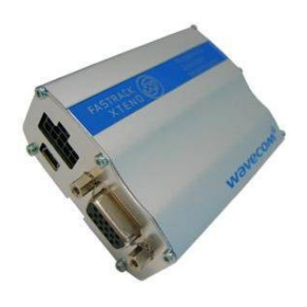
Fastrack Xtend User Guide Overview 1.2. Overall Dimensions Figure 1. Fastrack Xtend Table 2: Fastrack Xtend Physical Dimensions Length 89 mm Width 60 mm Thickness 30 mm Weight 97g for FXT001 and FXT002; 120g for FXT003 and FXT008 1.3. Fastrack Xtend Variants Table 3: Fastrack Xtend Variants Part Number... -
Page 20: Connections
Fastrack Xtend User Guide Overview 1.4. Connections One 10-pin Micro-Fit Power Supply Connector USB 2.0 One 15-pin Sub-D Serial Interface SIM Interface Antenna Interface SMA Main SMA Diversity (3G-HSxPA version) for FXT003 and FXT008; or SMA GPS-One (1xRTT version) for FXT004 1.5. -
Page 21: Environmental Compliance
Fastrack Xtend User Guide Overview 1.6. Environmental Compliance 1.6.1. RoHS Directive Compliant The Fastrack Xtend is compliant with RoHS Directive 2002/95/EC which sets limits for the use of certain restricted hazardous substances. This directive states that “from 1st July 2006, new electrical and electronic equipment put on the market does not contain lead, mercury, cadmium, hexavalent chromium, polybrominated biphenyls (PBB) or polybrominated diphenyl ethers (PBDE)”. -
Page 22: Features And Services
2. Features and Services This section enumerates the features and services available on the Fastrack Xtend series. 2.1. Features and Services Refer to the table below for the list of basic features available on the Fastrack Xtend. WA_DEV_FEX20_UGD_002 Rev 002 April 26, 2010... -
Page 23: Table 4: Fastrack Xtend Basic Features
Fastrack Xtend User Guide Features and Services Table 4: Fastrack Xtend Basic Features Features Description Sierra Wireless Software Suite programmable: Native execution of embedded standard ANSI C applications Sierra Wireless Custom AT command creation Software Suite ... - Page 24 Fastrack Xtend User Guide Features and Services Features Description UMTS Data Transfer BAND I, II, IV (850/1900,2100)up to 384kbits/s (for FXT003, FXT008) BAND I, II, IV (850/1900,2100) HSXPA HSDPA Cat 8 up to 7.2Mbits/s (for FXT003, FXT008) HSUPA Cat 5 up to 2Mbits/s (for FXT001, Automatic fax group 3 (class 1 and class 2)
- Page 25 Fastrack Xtend User Guide Features and Services Refer to the following table for the comparison list between the different Fastrack Xtend variants. WA_DEV_FEX20_UGD_002 Rev 002 April 26, 2010...
-
Page 26: Table 5: Fastrack Xtend Basic Features By Variant
Fastrack Xtend User Guide Features and Services Table 5: Fastrack Xtend Basic Features by Variant Feature FXT001 FXT002 FXT003 FXT004 FXT006 FXT007 FXT008 1800 1800 1800 1800 1800 1800 1800 1900 1900 1900 1900 1900 1900 1900 WCDMA 1900 1900 1900 1900 1900... - Page 27 Fastrack Xtend User Guide Features and Services Feature FXT001 FXT002 FXT003 FXT004 FXT006 FXT007 FXT008 Vocoder GPS One WA_DEV_FEX20_UGD_002 Rev 002 April 26, 2010...
-
Page 28: Supported Bands
Expansion Card through the mating connector of the Expansion Card interface. The Fastrack Xtend with an Ethernet Expansion Card or an IO+GPS Expansion Card plugged in is run by the Plug-Ins of the Sierra Wireless Software Suite, which is based on the firmware inside the Fastrack Xtend. -
Page 29: Figure 2. Suggested Expansion Card Dimension
Fastrack Xtend User Guide Features and Services Figure 2. Suggested Expansion Card Dimension Supported Expansion Cards for more information about the Expansion Cards supported by the Fastrack Xtend. WA_DEV_FEX20_UGD_002 Rev 002 April 26, 2010... -
Page 30: Protection
Fastrack Xtend User Guide Features and Services 2.4. Protection 2.4.1. Power Supply The Fastrack Xtend is protected from continuous over-voltage by a 2A/250V slow break fuse directly bonded on the power supply cable; and it is also protected against transient voltage peaks over +32V. When the input voltage exceeds 32V, the supply voltage is automatically disconnected in order to protect the internal electronic components from overvoltage. -
Page 31: Functional Specifications
3. Functional Specifications This section discusses the functional specifications of the Fastrack Xtend series. 3.1. Functional Architecture The global architecture of the Fastrack Xtend series is shown in the figure below. Figure 3. Functional Architecture WA_DEV_FEX20_UGD_002 Rev 002 April 26, 2010... -
Page 32: Rf Functionalities
3.3. Operating System The Fastrack Xtend is Sierra Wireless Software Suite compliant. With the Sierra Wireless Software Suite, customers can embed their own applications with the Fastrack Xtend and turn the Fastrack Xtend into a solution for their specific market need. The operating system of the Fastrack Xtend is also responsible for the following functions: ... -
Page 33: Technical Specifications
4. Technical Specifications 4.1. Power Supply The Fastrack Xtend is supplied by an external DC voltage, DC-IN, with a voltage range of +4.75V ~ +32V. The main regulation is made with an internal DC/DC converter in order to supply all the internal functions with a DC voltage. -
Page 34: Mechanical Specifications
Fastrack Xtend User Guide Technical Specifications 4.2. Mechanical Specifications Figure 5. Fastrack Xtend Mechanical Drawing WA_DEV_FEX20_UGD_002 Rev 002 April 26, 2010... -
Page 35: Interfaces
5. Interfaces This section describes the different interfaces that connect with the Fastrack Xtend. The Fastrack Xtend comes with the following interfaces: 10-pin Micro-Fit Connector USB Interface 15-pin Sub-D Serial Interface Main RF Interface Secondary RF Interface (for FXT003, FXT004 and FXT008 only) ... -
Page 36: General Purpose Input/Output
Fastrack Xtend User Guide Interfaces Figure 7. Power Supply Connector Refer to the following table for the pin description of the power supply connector. Table 8: Power Supply Connector Pin Description Pin # Signal Description GPIO25 General purpose input/output GPIO21 General purpose input/output Vref Voltage reference for the GPIOs... -
Page 37: Table 9: Gpio Pin Description
AT command AT+WIOM must be used to change this configuration. Refer to document [7] Firmware 7.4a AT Commands Manual (Sierra Wireless Software Suite 2.31)/Firmware 7.4 AT Commands Manual (Sierra Wireless Software Suite 2.30) for more information regarding this AT command. 5.1.1.1.1. -
Page 38: On/Off Pin
Fastrack Xtend User Guide Interfaces 5.1.1.2. ON/OFF Pin The Fastrack Xtend has an external ON/OFF pin which is used to turn the device ON or OFF. The following table describes the operation of this pin. Table 10: ON/OFF Pin Operation Condition State Power Supply... -
Page 39: Rs232 Serial Link Connection
Undefined Data Carrier Detect CT103/TXD +/- 5.5V Transmit Serial Data BOOT. This signal must not be connected. Its use is strictly reserved BOOT for Sierra Wireless or competent retailers. CMIC2P Analog Microphone positive input CMIC2N Analog Microphone negative input CT104/RXD +/- 5.5V... -
Page 40: Figure 9. Rs232 Serial Link Signals
Fastrack Xtend User Guide Interfaces Figure 9. RS232 Serial Link Signals The RS232 interface has been designed to allow flexibility in the use of the serial interface signals. However, the use of TXD, RXD, CTS and RTS signals are mandatory; while the use of DTR, DSR, DCD and RI signals are optional. -
Page 41: Figure 10. V24 Serial Link Implementation For A 5-Wire Uart
Fastrack Xtend User Guide Interfaces Figure 10. V24 Serial Link Implementation for a 5-wire UART 5.1.2.1.1.2. 4-wire Serial Interface RS232 Implementation The signals used in this interface are as follows: CT103/TXD CT104/RXD CT105/RTS CT106/CTS Figure 11. V24 Serial Link Implementation for a 4-wire UART 5.1.2.1.1.3. -
Page 42: Autobauding Mode
AT+WASR=0 to exit the serial port auto shut down mode Refer to document [7] Firmware 7.4a AT Commands Manual (Sierra Wireless Software Suite 2.31)/Firmware 7.4 AT Commands Manual (Sierra Wireless Software Suite 2.30) for more information on AT commands. -
Page 43: Audio Lines Connection
The microphone gain can be adjusted by AT+VGT and the transmit digital gain can be adjusted by AT+WDGT. Refer to [7] Firmware 7.4a AT Commands Manual (Sierra Wireless Software Suite 2.31)/Firmware 7.4 AT Commands Manual (Sierra Wireless Software Suite 2.30) for more information about these AT commands. -
Page 44: Table 16: Recommended Microphone Characteristics
-0.9 The input voltage depends of the input micro gain set by AT command. Refer to document [7] Firmware 7.4a AT Commands Manual (Sierra Wireless Software Suite 2.31)/Firmware 7.4 AT Commands Manual (Sierra Wireless Software Suite 2.30). Because MIC2P is internally biased, it is necessary to use a coupling capacitor to connect an audio signal provided by an active generator. -
Page 45: Figure 13. Equivalent Circuit Of Cspk2 Speaker Outputs
The output voltage depends of the output speaker gain set by AT command. Refer to document [7] Firmware 7.4a AT Commands Manual (Sierra Wireless Software Suite 2.31)/Firmware 7.4 AT Commands Manual (Sierra Wireless Software Suite 2.30). This value is given in dB, but it’s possible to toggle this to index value. -
Page 46: Usb Interface
Fastrack Xtend User Guide Interfaces 5.1.3. USB Interface Aside from the serial interface, the mini-USB interface (USB Slave) may also be used to directly communicate with the Fastrack Xtend. This USB slave feature is also used for USB charging feature if the optional battery accessory is available. -
Page 47: Back Interface
The USB feature can be activated by using the AT+WMFM=0,1,3 AT command. Refer to document [7] Firmware 7.4a AT Commands Manual (Sierra Wireless Software Suite 2.31)/Firmware 7.4 AT Commands Manual (Sierra Wireless Software Suite 2.30) for more information regarding this AT command. -
Page 48: Sim Socket Pin Description
Fastrack Xtend User Guide Interfaces 5.2.1.1. SIM Socket Pin Description Refer to the following table for the pin description of the SIM socket. Table 22: SIM Socket Pin Description Pin # Signal I/O Type Reset State Description SIMVCC 2V9 / 1V8 SIM Power Supply SIMRST 2V9 / 1V8... -
Page 49: Rf Performances (For Fxt001, Fxt002, Fxt006 And Fxt007)
Fastrack Xtend User Guide Interfaces 5.2.2.1. RF Performances (For FXT001, FXT002, FXT006 and FXT007) RF performances are compliant with ETSI recommendation GSM 05.05. Refer to the tables below for the main parameters used for both the Receiver and the Transmitter. Table 24: Main Receiver Parameters for FXT001, FXT002, FXT006, and FXT007 Parameters... -
Page 50: Antenna Specifications
Fastrack Xtend User Guide Interfaces 5.2.2.2. Antenna Specifications The antenna must meet the requirements specified in the table below. The optimum operating frequency depends on the application. A dual-band or quad-band antenna should operate in these frequency bands and have the following characteristics. Table 26: Antenna Specifications for FXT001, FXT002, FXT006, and FXT007 Characteristic... -
Page 51: Rf Performances (Fxt003 And Fxt008)
Fastrack Xtend User Guide Interfaces 5.2.3.1. RF Performances (FXT003 and FXT008) RF performances are compliant with ETSI recommendation GSM 05.05. Refer to the tables below for the main parameters used for both the Receiver and the Transmitter. Table 27: Main Receiver Parameters for FXT003 and FXT008 Parameters Values GSM850 Reference Sensitivity... -
Page 52: Antenna Specifications
Fastrack Xtend User Guide Interfaces 5.2.3.2. Antenna Specifications The antenna must meet the requirements specified in the table below. The optimum operating frequency depends on the application. The antenna should operate in these frequency bands and should have the following characteristics. Table 29: Antenna Specifications for FXT003 and FXT008 FXT003 and FXT008... -
Page 53: Signals And Indicators
A specific control pin, BOOT, is available to download to the Fastrack Xtend. Specific PC software, provided by Sierra Wireless, is needed to perform this download, specifically for the first download of the Flash memory. Caution: This signal must not be connected. Its use is strictly reserved for Sierra Wireless or competent retailers. 6.3. -
Page 54: Reset Sequence
Fastrack Xtend User Guide Signals and Indicators When used (as an emergency reset), it has to be driven by either an open collector or an open drain output. Caution: This signal is for emergency resets only. Table 31: Fastrack Xtend Reset Status (Serial Signal I/O Type... -
Page 55: Led Status Indicator
The Flash LED can be disabled by the user when in Sleep mode in order to save power consumption. Refer to section 10.1 Enabling/Disabling the Flash LED and document [7] Firmware 7.4a AT Commands Manual (Sierra Wireless Software Suite 2.31)/Firmware 7.4 AT Commands Manual (Sierra Wireless Software Suite 2.30) for more information on how to disable the Flash LED using an AT command. -
Page 56: Real Time Clock (Rtc)
Fastrack Xtend User Guide Signals and Indicators 6.5. Real Time Clock (RTC) The Fastrack Xtend has implemented Real Time Clock for saving date and time when the Fastrack Xtend is unplugged from the DC power supply through the DC power cable. Table 35: Real Time Clock Specifications Item... -
Page 57: Expansion Card
7. Expansion Card 7.1. Expansion Card Compartment The Expansion Card compartment allows users to easily expand the Fastrack Xtend’s features (IO+GPS, Ethernet expander) for their own applications. 7.1.1. Back Plate Screws Unscrew the two back plate screws to remove the back plate and open the Expansion Card compartment. -
Page 58: Table 36: 50-Pin Expansion Card Connector Description
Fastrack Xtend User Guide Expansion Card Table 36: 50-pin Expansion Card Connector Description Pin # Pin Description Pin # Pin Description RTS2 Reserved Reserved GPIO26 Reserved GPIO19 Reserved GPIO27 Reserved GPIO20 INT0/GPIO3 GPIO23 GPIO22 1.8V Digital supply from the embedded module DTR1-CT108/2 2.8V Digital supply from the embedded module PCM-SYNC... -
Page 59: Expansion Card Physical Description
Fastrack Xtend User Guide Expansion Card 7.2. Expansion Card Physical Description Refer to the figure below for the physical dimensions of the Expansion Card. Figure 21. Expansion Card Size 7.3. Expansion Card Design Suggestion Refer to the following diagram for suggested dimensions when using a customized expansion card. WA_DEV_FEX20_UGD_002 Rev 002 April 26, 2010... -
Page 60: Figure 22. Suggested Expansion Card Dimension
Fastrack Xtend User Guide Expansion Card Figure 22. Suggested Expansion Card Dimension WA_DEV_FEX20_UGD_002 Rev 002 April 26, 2010... -
Page 61: Supported Expansion Cards
The basic features of the Ethernet Expansion Card are summarized in the table below. Table 38: Basic Features of the Ethernet Expansion Card Features Description Sierra Wireless Software Suite programmable: Native execution of embedded standard ANSI C applications Sierra Wireless ... -
Page 62: Board Architecture
Fastrack Xtend User Guide Expansion Card 7.4.1.2. Board Architecture Figure 24. Ethernet Expansion Card Architecture WA_DEV_FEX20_UGD_002 Rev 002 April 26, 2010... -
Page 63: Figure 25. Ethernet Expansion Card With Rj-45 Interface Cable
Fastrack Xtend User Guide Expansion Card Figure 25. Ethernet Expansion Card with RJ-45 Interface Cable The 10-Pin Interface Socket is an external interface for the RJ-45 cable. Figure 26. 10-Pin Interface Socket WA_DEV_FEX20_UGD_002 Rev 002 April 26, 2010... -
Page 64: Mechanical Characteristics
Electrical Characteristics 4V DC Operating Voltage Note: The Ethernet Expansion Card is powered once the enable pins are activated by the Sierra Wireless Software Suite. 7.4.1.5. Extra Current Consumption from the DC-IN Source Depending on various DC-IN voltages of the Fastrack Xtend, the extra current consumption drawn by the Ethernet Expansion Card will also vary. -
Page 65: Io+Gps
All DC supplies are applied through this connector so no external supply is necessary. With the Sierra Wireless Software Suite running, the Fastrack Xtend motherboard communicates with the IO+GPS Expansion Card on UART2. The GPS module communicates on UART2 using the following configuration: ... -
Page 66: Io+Gps Expansion Card Installation
Fastrack Xtend User Guide Expansion Card The Sierra Wireless Software Suite controls the following: Enables/disables the internal LDOs of the Expansion Card to power-up the GPS Enables/disables the RF block of the GPS Enables a trigger to reset the GPS module ... -
Page 67: Mechanical Characteristics
Fastrack Xtend User Guide Expansion Card 7.4.2.2. Mechanical Characteristics Table 43: Mechanical Characteristics 58mm x 35.7mm x 1mm PCB Dimensions 59.5 x 35.7 x 10.01mm (including connectors) Overall Dimension < 10 grams Weight Figure 30. 16-Way IO Expander Socket Table 44: 16-Way IO Expander Description Pin # Pin Description... -
Page 68: General Purpose Input/Output
Electrical Characteristics Operating Voltage 4V DC Note: The IO+GPS Expansion Card is powered once the enable pins are activated by the Sierra Wireless Software Suite. 7.4.2.5. Extra Current Consumption from the DC-IN Source Depending on various DC-IN voltage of Fastrack Xtend, the extra current consumption drawn by the GPS feature and the GPS active antenna will be different. -
Page 69: Gps Receiver Frequency
Fastrack Xtend User Guide Expansion Card 7.4.2.6. GPS Receiver Frequency Table 48: GPS Receiver Frequency Characteristic Frequency RX 1575.42 MHz 7.4.2.7. External Antenna The external antenna is connected to the Expansion Card‟s GPS via the MMCX connector. The external antenna must fulfill the characteristics listed in the table below. Table 49: External Antenna Characteristics 1.57542GHz ±... -
Page 70: Expansion Card Removal
Fastrack Xtend User Guide Expansion Card 7.5. Expansion Card Removal To remove the Expansion Card from the Fastrack Xtend, insert the extraction tool hook into the Expansion Card extraction hole located under the PCB. Once in place, pull the extraction tool to extract the Expansion Card from the Fastrack Xtend. -
Page 71: Using The Fastrack Xtend
8. Using the Fastrack Xtend 8.1. Mounting the Fastrack Xtend The holding bridles help hold and secure the Fastrack Xtend on a support. Figure 32. Fastrack Xtend Holding Bridles To mount the Fastrack Xtend on its support, bind it using the holding bridles as shown in the figure below. -
Page 72: Getting Started
Fastrack Xtend User Guide Using the Fastrack Xtend 8.2. Getting Started To set up the Fastrack Xtend, follow the procedures below. 1. Insert the SIM card into the SIM card socket. (Refer Inserting the SIM Card Extracting the SIM Card for more details on how to insert and extract the SIM card from the Fastrack Xtend.) Slide the SIM lock switch to lock the SIM card in... - Page 73 Fastrack Xtend User Guide Using the Fastrack Xtend Connect the serial cable and screw both sides. 5. Plug the power supply cable into the Fastrack Xtend and switch on the external power supply source. Refer to section 9.7 Main AT Commands for the Fastrack Xtend for the list of main AT Commands used to configure the Fastrack Xtend.
-
Page 74: Inserting The Sim Card
Fastrack Xtend User Guide Using the Fastrack Xtend 8.2.1. Inserting the SIM Card In order to insert the SIM card into the Fastrack Xtend, follow the procedures below: 1. Prepare the SIM card in the correct position as shown in the figure. 2. -
Page 75: Extracting The Sim Card
Fastrack Xtend User Guide Using the Fastrack Xtend 8.2.2. Extracting the SIM Card In order to extract the SIM card from the Fastrack Xtend, follow the procedures below: 1. Open the SIM lock switch by sliding it to the left. Use a tool to further push the SIM card into the SIM holder. -
Page 76: Using The Fastrack Xtend With An Expansion Card
Fastrack Xtend User Guide Using the Fastrack Xtend 8.3. Using the Fastrack Xtend with an Expansion Card Refer to section 7 Expansion Card for more information about using the Fastrack Xtend with an Expansion Card. Refer to section 19.3 Expansion Card Documentation for the list of documents containing additional information on how to use different Expansion Cards with the Fastrack Xtend. -
Page 77: Communicating With The Fastrack Xtend
9. Communicating with the Fastrack Xtend After setting up the Fastrack Xtend, communications can be established by directly sending AT commands to the device using terminal software such as HyperTerminal for MS Windows. The following subsections describe how this is done. Caution: Some AT commands and features in this section are not available in FXT004. -
Page 78: Verifying The Received Signal Strength
Fastrack Xtend User Guide Xtend For more information about these AT Commands and their associated parameters, refer to document [7] Firmware 7.4a AT Commands Manual (Sierra Wireless Software Suite 2.31)/Firmware 7.4 AT Commands Manual (Sierra Wireless Software Suite 2.30). 9.2. -
Page 79: Checking The Band Selection
When x = 1, the band has been modified since the last boot of the Fastrack Xtend, and will have to be reset in order to take the previous modification(s) into account. Refer to document [7] Firmware 7.4a AT Commands Manual (Sierra Wireless Software Suite 2.31)/Firmware 7.4 AT Commands Manual (Sierra Wireless Software Suite 2.30) for more information regarding the AT+WMBS AT Command. -
Page 80: Switching Bands
When x = 1, the band switch is effective immediately. However, this mode is forbidden while in Communication mode and during the Fastrack Xtend’s initialization. Refer to document [7] Firmware 7.4a AT Commands Manual (Sierra Wireless Software Suite 2.31)/Firmware 7.4 AT Commands Manual (Sierra Wireless Software Suite 2.30) for more information regarding the AT+WMBS AT Command. -
Page 81: Main At Commands For The Fastrack Xtend
The table below lists the main AT Commands required for starting the Fastrack Xtend. For other available AT Commands, refer to document [7] Firmware 7.4a AT Commands Manual (Sierra Wireless Software Suite 2.31)/Firmware 7.4 AT Commands Manual (Sierra Wireless Software Suite 2.30). -
Page 82: Echo Function
Fastrack Xtend’s echo function (using the ATE0 AT command) in order to avoid useless embedded module processing. Refer to document [7] Firmware 7.4a AT Commands Manual (Sierra Wireless Software Suite 2.31)/Firmware 7.4 AT Commands Manual (Sierra Wireless Software Suite 2.30) for more information about the ATE0 and ATE1 AT Commands. -
Page 83: Other Maintenance Options
You will need to restart the Fastrack Xtend for the new setting to take effect. Refer to document [7] Firmware 7.4a AT Commands Manual (Sierra Wireless Software Suite 2.31)/Firmware 7.4 AT Commands Manual (Sierra Wireless Software Suite 2.30) for more information about enabling/disabling Flash LED. -
Page 84: Troubleshooting The Fastrack Xtend
11. Troubleshooting the Fastrack Xtend This section of the document describes possible problems that might be encountered when using the Fastrack Xtend and their corresponding solutions. To read about other troubleshooting information, refer to the Knowledge Base page at http://www.sierrawireless.com/en/Support/knowledgebase.aspx. 11.1. -
Page 85: Receiving "Error
+CMS ERROR: <error result code> Refer to document [7] Firmware 7.4a AT Commands Manual (Sierra Wireless Software Suite 2.31)/Firmware 7.4 AT Commands Manual (Sierra Wireless Software Suite 2.30) for more information on the error result code description and further details on the AT+CMEE command. -
Page 86: Table 60: Extended Error Codes
3, 6, 8, 29, 34, 38, 41, 42, Network causes Refer to document [7] Firmware 7.4a AT 43, 44, 47, 49, 57, 58, 63, Commands Manual (Sierra Wireless 65, 69, 70, 79, 254 Software Suite 2.31)/Firmware 7.4 AT Commands Manual (Sierra Wireless Software Suite 2.30) for further details or call... -
Page 87: Power Consumption
Refer to the table below for the different kinds of operating modes available. Refer to Appendix 3.1 of document [7] Firmware 7.4a AT Commands Manual (Sierra Wireless Software Suite 2.31)/Firmware 7.4 AT Commands Manual (Sierra Wireless Software Suite 2.30) for the working mode description. Table 62:... -
Page 88: Working Mode Features
Fastrack Xtend User Guide Power Consumption Operating Mode Description Alarm Mode Low power consumption mode, the only feature which is available in this mode is the alarm wake up. When the alarm clock is set for the Fastrack Xtend with ALL of the following conditions: ... - Page 89 Fastrack Xtend User Guide Power Consumption ACTIVE SLEEP Mode Mode Alarm ACTIVE SLEEP Connected Transfer Features with GSM with GSM Mode Mode Mode Mode Mode Stack in Stack in Idle Idle Flash led WA_DEV_FEX20_UGD_002 Rev 002 April 26, 2010...
-
Page 90: Power Consumption In Connected Mode (Fxt002)
Fastrack Xtend User Guide Power Consumption 12.3. Power Consumption in Connected Mode (FXT002) Table 64: Power Consumption of FXT002 in Connected Mode (Typical) Power Consumption (Serial Port ON, Flash GSM 850 E-GSM PCS 1900 LED activated) (mA) 900 (mA) 1800(mA) (mA) GSM850 / E-GSM900: @ 4.75V... - Page 91 Fastrack Xtend User Guide Power Consumption Power Consumption (Serial Port ON, Flash GSM 850 E-GSM PCS 1900 LED activated) (mA) 900 (mA) 1800(mA) (mA) GSM850 / E-GSM900: peak During 1TX bursts @ PCL8 (Gamma 6) / PCL19(Gamma @ 4.75V 1549 / 682 1553 / 634 1745 / 588 1872 / 618...
-
Page 92: Power Consumption In Connected Mode (Fxt003)
Fastrack Xtend User Guide Power Consumption 12.4. Power Consumption in Connected Mode (FXT003) Table 65: Power Consumption of FXT003 in Connected Mode (Typical) Power Consumption for FXT003 (Serial Port ON, GSM 850 E-GSM 900 DCS 1800 PCS 1900 Flash LED activated) GSM850 / E-GSM900: @ 4.75V 3600 / 690... - Page 93 Fastrack Xtend User Guide Power Consumption Power Consumption for FXT003 (Serial Port ON, GSM 850 E-GSM 900 DCS 1800 PCS 1900 Flash LED activated) (Gamma 3) @ 13.2V DCS1800 / PCS1900: Average 4TX/1RX @ PCL0 @ 32V (Gamma 3) GSM850 / E-GSM900: @ 4.75V 2128 2148...
- Page 94 Fastrack Xtend User Guide Power Consumption Power Consumption (Serial UMTS 850 (BAND I) UMTS 1900 (BAND II) UMTS 2100 (BAND V) Port ON, Flash LED activated) @4.75 @ +22dBm @13.2 peak @4.75 @ +10dBm @13.2 @4.75 @13.2 @ +22dBm @32V av g @4.75 @13.2...
-
Page 95: Power Consumption In Non-Connected Mode (Fxt002)
Fastrack Xtend User Guide Power Consumption Power Consumption (Serial UMTS 850 (BAND I) UMTS 1900 (BAND II) UMTS 2100 (BAND V) Port ON, Flash LED activated) @ +10dBm @13.2 @32V @4.75 1003 @ +22dBm @13.2 peak @4.75 @ +10dBm @13.2 @4.75 @ +22dBm @13.2... -
Page 96: Power Consumption In Non-Connected Mode (Fxt003)
Fastrack Xtend User Guide Power Consumption @ 13.2V @ 32V Non-connected mode Serial Port Status Voltage Current (mA) @ 4.75V 52.5 @ 13.2V 18.7 in ACTIVE mode with GSM @ 32V stack in Idle Page 9 @ 4.75V 21.1 @ 13.2V @ 32V @ 4.75V @ 13.2V... - Page 97 Fastrack Xtend User Guide Power Consumption Non-connected mode Serial Port Status Voltage Current (mA) @ 32V @ 4.75V in Alarm mode @ 13.2V @ 32V Non-connected mode Serial Port Status Voltage Current (mA) @ 4.75V 54.8 @ 13.2V 19.2 @ 32V in ACTIVE Idle mode 2G Page 9 @ 4.75V...
-
Page 98: Consumption Measurement Procedure
The Fastrack Xtend consumption specification values are measured for all operating modes available. For more information about switching between the operating modes, refer to the appendix of document [7] Firmware 7.4a AT Commands Manual (Sierra Wireless Software Suite 2.31)/Firmware 7.4 AT Commands Manual (Sierra Wireless Software Suite 2.30). -
Page 99: Sim Cards Used
A description of the operating modes and the procedures used to change operating modes are given in the appendix of document [7] Firmware 7.4a AT Commands Manual (Sierra Wireless Software Suite 2.31)/Firmware 7.4 AT Commands Manual (Sierra Wireless Software Suite 2.30). -
Page 100: Equipment Configuration
Fastrack Xtend User Guide Power Consumption Connected Mode (in UMTS mode)* Data Transfer (in UMTS mode and HSxPA mode)* Note: * For FXT003, FXT008 12.7.2.2. Equipment Configuration The communication tester is set according to the Fastrack Xtend operating mode. Paging during idle modes, Tx burst power, RF band and GSM/DCS/GPRS may be selected on the communication tester. - Page 101 Fastrack Xtend User Guide Power Consumption Operating Mode Communication Tester Configuration Transfer Mode class 12 850/900 MHz Gam.6 (TX power 27dBm) (1Rx/4Tx) Gam.17 (TX power 5dBm) 1800/1900 MHz Gam.5 (TX power 26dBm) Gam.18 (TX power 0dBm) +22dBm UMTS 850 (BAND I) +10dBm UMTS +22dBm...
-
Page 102: Recommendations When Using The Fastrack Xtend On Trucks
13. Recommendations when Using the Fastrack Xtend on Trucks Caution: The power supply connection of the Fastrack Xtend must never be directly connected to the truck battery. 13.1. Recommended Power Supply Connection on Trucks All trucks have a circuit breaker on the exterior of the cabin. The circuit breaker is used for safety reasons: if a fire blazes in the trucks, (for example, on the wiring trunk) the driver may cut the current source to avoid any damage (explosion). -
Page 103: Technical Constraints On Trucks
Recommendations when Using the Fastrack Xtend User Guide Fastrack Xtend on Trucks 13.2. Technical Constraints on Trucks It is highly recommended to directly connect the power supply on the circuit breaker rather than on the battery. The Fastrack Xtend may be damaged when starting the truck if the circuit breaker is switched OFF (in this case, the truck ground and the battery ground will be connected through the Fastrack Xtend as shown in the following figure). -
Page 104: Fastrack Xtend Accessories
14. Fastrack Xtend Accessories 14.1. Standard Accessories The Fastrack Xtend has the following standard accessories: Six-wire power supply cable with IO (DC IN, GND, VRef, GPIO25, GPIO21, ON/OFF) (Refer to the following table for the color-coding of the 6-wire power cable.) ... -
Page 105: Component Recommendations
In: 100 to 240V – 47/63 Hz – 550mA Mounted with micro-fit connector Cable: K96975060049A 6-Wire Power cable + Fuse Grand-TEK Technology FUSE: T2AL250V VDE Slow Break IO+GPS Expansion Card FXTE01 Sierra Wireless GPS antenna GC-GAACZ-A55 GIGA-Concept IO cable for Expansion Card 58-9257-000-000-012S FXTE02 Sierra Wireless... -
Page 106: Recommendations When Using The Battery Accessory
15. Recommendations when Using the Battery Accessory The figure below displays the battery accessory with its interface connector plug. The battery accessory consists of an internal battery with a built-in slow charger; while the interface connector is used to connect the battery accessory with the Fastrack Xtend series. Figure 37. -
Page 107: Using The Battery Accessory
Recommendations when Using the Fastrack Xtend User Guide Battery Accessory Refer to the battery specification table below for the battery temperature range. Table 72: Battery Specifications Specification Value Battery Cell Type Nickel Metal hydride (Ni-MH) Capacity 500mAH Storage (Less than 30 days) -40°C to +85°C Discharge Temperature -20°C to +85°C... -
Page 108: Led Indicator
Recommendations when Using the Fastrack Xtend User Guide Battery Accessory 15.2. LED Indicator The charger operation status is defined by the bi-color LED indicator. Refer to the following table for the operational details of the LED indicator. Table 73: LED Indicator Status LED Light Activity Charger Status Red LED ON... -
Page 109: Ni-Mh Battery Level Reading
+WIOR: 1 No DC-IN detected (using battery as power supply) Refer to document [7] Firmware 7.4a AT Commands Manual (Sierra Wireless Software Suite 2.31)/Firmware 7.4 AT Commands Manual (Sierra Wireless Software Suite 2.30) for more information regarding the AT+WIOR AT Command. -
Page 110: Battery Accessory Recommendations And Other Information
Recommendations when Using the Fastrack Xtend User Guide Battery Accessory 15.6. Battery Accessory Recommendations and Other Information When used for the first time, or after a long time (more than a month) of storage, 2 to 3 times of charging and discharging cycles are required to optimize the battery performance (capacity). -
Page 111: Reliability Standards: Compliance And Recommendations
16. Reliability Standards: Compliance and Recommendations 16.1. Reliability Compliance The Fastrack Xtend is compliant with the following requirements. Table 77: Standards Conformity for the Fastrack Xtend Series Abbreviation Definition International Electro technical Commission International Organization for Standardization 16.2. Applicable Standards Listing The table hereafter gives the basic list of standards applicable to the Fastrack Xtend. -
Page 112: Environmental Specifications
Reliability Standards: Compliance and Fastrack Xtend User Guide Recommendations Current Document Title Version Environmental testing - part 2-38: Test Z/AD: composite IEC60068238 temperature/humidity cyclic test. Basic environmental testing procedures - part 2: Test Z/AM combined IEC60068240 1.0 w/A1 cold/low air pressure tests. Road vehicles - environmental conditions and testing for electrical and ISO167501 electronic equipment - part 1: general. -
Page 113: Function Status Classification
Reliability Standards: Compliance and Fastrack Xtend User Guide Recommendations 16.3.1. Function Status Classification The classes reported below comply with the Annex “ISO Failure Mode Severity Classification”, ISO Standard 7637, and Section 1. Note: The word “function” used here only concerns the function performed by the Fastrack Xtend. Table 80: ISO Failure Mode Severity Classification Class... -
Page 114: Environmental Resistance Stress Tests
Reliability Standards: Compliance and Fastrack Xtend User Guide Recommendations 16.3.2.2. Environmental Resistance Stress Tests The following tests the Fastrack Xtend’s resistance to extreme temperature. Table 82: Environmental Resistance Stress Tests Designation Condition Standard: IEC 680068-2-1, Test Ab Cold Test Special conditions: ... -
Page 115: Thermal Resistance Cycle Stress Test
Reliability Standards: Compliance and Fastrack Xtend User Guide Recommendations 16.3.2.4. Thermal Resistance Cycle Stress Test The following tests the Fastrack Xtend‟s resistance to extreme temperature cycling. Table 84: Thermal Resistance Cycle Stress Tests Designation Condition Standard: IEC 60068-2-14 Special conditions: Thermal Shock Test ... - Page 116 Reliability Standards: Compliance and Fastrack Xtend User Guide Recommendations Designation Condition Special conditions: Density spectrum: 0.96m Frequency range: 0.1 g /Hz at 10Hz 0.01 g /Hz at 250Hz 0.0005 g /Hz at 1000Hz 0.0005 g /Hz at 2000Hz ...
-
Page 117: Handling Resistance Stress Tests
Reliability Standards: Compliance and Fastrack Xtend User Guide Recommendations 16.3.2.6. Handling Resistance Stress Tests The following tests the Fastrack Xtend‟s resistance to handling malfunctions and damage. Table 86: Handling Resistance Stress Tests Designation Condition ESD Test Standard: IEC 1000-4-2 Special conditions: ... -
Page 118: Certification Compliance And Recommended Standards
17. Certification Compliance and Recommended Standards 17.1. Certification Compliance The Fastrack Xtend is compliant with the following requirements. Table 87: Standards Conformity for the Fastrack Xtend Series Domain Applicable Standard Safety standard EN 60950-1 (ed.2006) Health standard (EMF Exposure Evaluation) EN 62311 (ed. - Page 119 Certification Compliance and Fastrack Xtend User Guide Recommended Standards Document Current Title Version requirements under article 3.2 of the R&TTE directive (1999/5/EC) 3rd Generation Partnership Project; Technical Specification Group Radio Access Network; User Equipment (UE) conformance specification; Radio transmission TS 34.121-1 8.5.0 and reception (FDD);...
-
Page 120: Safety Recommendations
18. Safety Recommendations 18.1. General Safety It is important to follow any special regulations regarding the use of radio equipment due in particular to the possibility of radio frequency (RF) interference. Please follow the safety advice given carefully. Switch OFF your Intelligent Embedded Module: ... -
Page 121: Battery Safety
Fastrack Xtend User Guide Safety Recommendations 18.2. Battery Safety Storage Temperature (< 30 days): -40°C to 85°C Charging Temperature: -20°C to 85°C Discharging Temperature: 0°C to 85°C Do not use batteries not specified for this product. Do not recharge non-rechargeable batteries. Charge only NiMH 3x1.2V rechargeable batteries. Charging other types of batteries (e.g. -
Page 122: Your Responsibility
Fastrack Xtend User Guide Safety Recommendations The use of third party equipment or accessories, not made or authorized by Sierra Wireless may invalidate the warranty of the embedded module. Do contact an authorized Service Center in the unlikely event of a fault in the embedded module. -
Page 123: Reference Documents
For more details, several reference documents can be consulted. The Sierra Wireless documents referenced herein are provided in the Sierra Wireless documentation package; however, the general reference documents which are not Sierra Wireless owned are not provided in the documentation package. -
Page 124: Expansion Card Documentation
Fastrack Xtend User Guide Reference Documents 19.3. Expansion Card Documentation [11] Expansion Card Product Technical Specification Reference: WA_DEV_FEX20_PTS_004 [12] FXTE01 and FXTE02 User Guide Reference: WA_DEV_FEX20_UGD_008 [13] FXTE01 and FXTE02 Installation Guide Reference: WA_DEV_FEX20_UGD_009 [14] Ethernet Expansion Card Plug-in User Guide Reference: TBC 19.4. -
Page 125: List Of Abbreviations
20. List of Abbreviations Abbreviation Definition Alternating Current Accumulated Call Meter Adaptive Multi-Rate ® ATtention (prefix for Wireless CPU commands) CLocK CMOS Complementary Metal Oxide Semiconductor Coding Scheme Clear To Send Decibel Decibel relative to the Carrier power Decibel relative to an Isotropic radiator Decibel relative to one milliwatt Direct Current Data Carrier Detect... - Page 126 Fastrack Xtend User Guide List of Abbreviations Abbreviation Definition IMEI International Mobile Equipment Identification Input / Output Light Emitting Diode MAXimum Mobile Equipment MICrophone Micro-Fit Family of connectors from Molex MINimum Microcom Networking Protocol Mobile Originated Mobile Station Mobile Terminated NOMinal Output Pascal (for speaker sound pressure measurements)
-
Page 127: Appendix A: Packaging
21. Appendix A: Packaging 21.1. Contents The Fastrack Xtend is available in four package configurations. 21.1.1. Package Configuration 1 One Packaging box One Fastrack Xtend Two Holding bridles USB Cable Power Cable used with the Fastrack Xtend ... -
Page 128: Package Configuration 2
Fastrack Xtend User Guide Appendix A: Packaging 21.1.2. Package Configuration 2 One Packaging box One Fastrack Xtend Two Holding bridles USB Cable Power Cable used with the Fastrack Xtend Battery Accessory Pack Battery cable used with the battery accessory ... -
Page 129: Package Configuration 3
Fastrack Xtend User Guide Appendix A: Packaging 21.1.3. Package Configuration 3 One Packaging box One Fastrack Xtend Two Holding bridles USB Cable Serial Data Cable Power Cable used with the Fastrack Xtend Power supply used with the Fastrack Xtend ... -
Page 130: Package Configuration 4
Fastrack Xtend User Guide Appendix A: Packaging 21.1.4. Package Configuration 4 One Packaging box One Fastrack Xtend Two Holding bridles USB Cable Serial Data Cable Power Cable used with the Fastrack Xtend Power supply used with the Fastrack Xtend ... -
Page 131: Physical Characteristics
Fastrack Xtend User Guide 21.2. Physical Characteristics The Fastrack Xtend comes in two types of packaging box with the following external dimensions. 21.2.1. Packaging Box 1 Width: 110mm Length: 170mm Height: 80mm Figure 44. Packaging Box 1 21.2.2. -
Page 132: Appendix B: Product Labeling
22. Appendix B: Product Labeling A product label located at the back of the Fastrack Xtend gives the following information: Product Reference (Fastrack Xtend FXT002 for example) Part number (WM24628 for example) CE marking 15-digit Serial Number ... -
Page 133: Appendix C: Safety Recommendations (For Information Only)
23. Appendix C: Safety Recommendations (For Information Only) For the efficient and safe operation of your GSM device, please read the following information carefully. 23.1. RF Safety 23.1.1. General Your GSM terminal is based on the GSM standard for cellular technology. The GSM standard is spread all over the world. -
Page 134: General Safety
Appendix C: Safety Recommendations Fastrack Xtend User Guide (For Information Only) see if you may change the antenna yourself. If so, use only a manufacturer-approved antenna. Otherwise, have your antenna repaired by a qualified technician. Use only the supplied or approved antenna. Unauthorized antennas, modifications or attachments could damage the terminal and may contravene local RF emission regulations or invalidate type approval. -
Page 135: Children
Appendix C: Safety Recommendations Fastrack Xtend User Guide (For Information Only) is on the ground. To prevent interference with cellular systems, local RF regulations prohibit using your modem while airborne. 23.2.6. Children Do not allow children to play with your GSM terminal. It is not a toy. Children could hurt themselves or others (by poking themselves or others in the eye with the antenna, for example).
Need help?
Do you have a question about the AirLink FXT Series and is the answer not in the manual?
Questions and answers