
Related Manuals for MicroNet SP915A


Summary of Contents for MicroNet SP915A
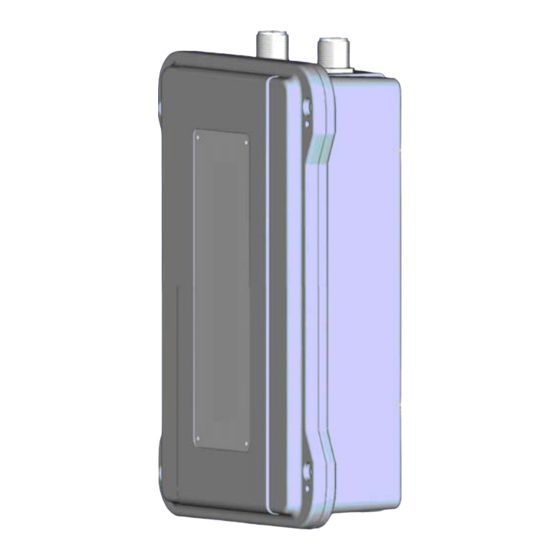
- Page 1 User’s Manual Wireless LAN Outdoor AP/Bridge Model No.: SP915A http://www.micronet.info...
-
Page 2: Table Of Contents
1.3 LED Indicator ....................2 Chapter 2 Installation and Configuration ............3 2.1 Mounting the SP915A................... 3 2.2 Connecting the Managing PC and the SP915A..........5 2.3 Preparing for Configuration................5 2.4 Accessing Web-based User Interface ............7 2.5 Quick Setup via Web-Based UI..............8 2.5.1 Operational Mode....................8... - Page 3 3.4.2 Changing Password..................20 3.4.3 Managing Firmware ..................21 3.5 TCP/IP Related Settings ................22 3.5.1 Addressing......................22 3.5.2 Static DHCP Mappings...................23 3.6 IEEE 802.11 Menu..................24 3.6.1 Communication....................24 3.6.2 Security ......................27 3.6.3 IEEE 802.1x/RADIUS ..................31 3.7 Configuring Advanced Settings..............33 3.7.1 Packet Filters ....................33 3.7.2 Management ....................35 Chapter 4 Appendix..................
-
Page 4: Chapter 1 Introduction
Chapter 1 Introduction Micronet proudly introduces SP915A, high power outdoor Access Point. It is compliant with IEEE 802.11a/b/g for providing speed of up to 54/54/11Mbps respectively. The AP includes a Web-Based User Interface for easy management of your wireless network. Security is intact with WEP, WPA and 802.1x for preventing unauthorized access in wireless environment. -
Page 5: Led Indicator
System Log: local log and remote log by SNMP. Supplying power to an AP over an Ethernet cable using PowerDsine. LED Indicator There are several LED indicators inside the housing of the SP915A. They are defined as follows: ALV: Alive. Blinks when the AP is working normally. -
Page 6: Chapter 2 Installation And Configuration
Follow steps below to mount SP915A with a wall-mount kit #1. 1. Put the M6*90 screw into wall mount #1. 2. Fix the wall mount #1 to the bottom of SP915A by using M4*80 screw. 3. Fix the SP915A to the pole with the wall mount #1 using M6*90 screw. - Page 7 4. Screw a supplied ST3.9*20 screw in each plastic conical anchor for a proper depth so that the wireless AP can be hung on the screws. 5. Fix two wall mounts #1 to the bottom of SP915A by using two M4*80 screws.
-
Page 8: Connecting The Managing Pc And The Sp915A
LAN/CONFIG Ethernet jack of the SP915A for configuration.) Preparing for Configuration For users to configure the SP915A, a managing computer with a Web browser is needed. For first-time configuration of an SP915A, an Ethernet network interface card (NIC) should have been installed in the managing computer. - Page 9 PC/Notebook must belong in the same IP range and subnet. Follow the steps below to configure IP settings for LAN PC. Step 1. In the control panel, double click on Network Connections. Double click on the local area connection (e.g. LAN). The following screen will appear.
-
Page 10: Accessing Web-Based User Interface
Password root Accessing Web-based User Interface SP915A is embedded with web-based management user interface and provides a series of web pages, which display the configuration and status of the system. After configuration of IP, the management interface can be access by entering the IP address of the router into the browser. -
Page 11: Quick Setup Via Web-Based Ui
Quick Setup via Web-Based UI Follow the following steps for quick setup of your wireless AP. Click <Save> at the bottom of each configuration interface to save changes. 2.5.1 Operational Mode Go to the ‘General’ menu and click <Operational Mode> to select a mode for the AP. - Page 12 AP Client: This mode is for Dynamic LAN-to-LAN Bridging. The AP Client automatically establishes bridge links with APs from any vendors. In either mode, the AP forwards packets between its Ethernet interface and wireless interface for wired hosts on the Ethernet side and wireless host(s) on the wireless side.
-
Page 13: Ip Address
2.5.2 IP Address Go to the ‘TCP/IP’ menu and click <Addressing> to alter the IP configuration for the AP. 2.5.3 Wireless Settings Go to the ‘IEEE 802.11’ menu and click <Communication> to set wireless parameters for the AP. 2.5.4 Restart Device After pressing <Save>... -
Page 14: Installation
Installation For configuring a pair of APs for dynamic or static bridging with high grain directional antenna, please follow the steps below. Step 1. Connect each bridge to a computer via Ethernet and configure the data rate of each AP to the lowest value, 1Mbps. Step 2. -
Page 15: Setting Up Client Computers
The TCP/IP and IEEE 802.11b-related settings of wireless client computers must match those of the AP. 2.7.1 Configuring SP915A Related Settings Before the TCP/IP networking system of a wireless client computer can communicate with other hosts, the underlying wireless link must be established between this wireless computer and an AP. - Page 16 A wireless client computer must be in infrastructure mode, so that it can associate with an AP. The SSID of the wireless client computer and the SSID of the AP must be identical. Or, in case the SSID broadcasts capability of the AP is enabled (by default), the SSID of the wireless client computer could be set to “any”.
-
Page 17: Chapter 3 Web-Based Management
Chapter 3 Web-Based Management The following chapter will outline the web-based user interface used for configuring SP915A. Overview Once, the login details are correctly entered, the web browser will proceed to the following page containing overview of AP’s settings. Menu Structure The left side of the start page contains a menu for users to carry out commands. -
Page 18: Save, Save & Restart, And Cancel
DHCP Mappings: Current IP-MAC Address mappings of the built- in DHCP server. System Log: System events log. Link Monitor: When the AP is in AP Client mode, this page shows the signal strength and link quality of the wireless link to its associated access point. - Page 19 Restart> stores the settings changes to the memory of the AP and restarts the AP immediately for the settings changes to take effect. Clicking <Cancel> discards any settings changes and brings users back to the start page. If users click <Save>, the start page will reflect the changed settings and followed by two buttons: <Restart>...
-
Page 20: Home And Refresh
3.2.2 Home and Refresh At the bottom of each status page that shows read-only information, there are two buttons: <Home> and <Refresh>. Clicking <Home> brings user back to the start page. Clicking <Refresh> updates the status information. Status Menu 3.3.1 Wireless Clients On this page, the status information of each associated client, including its MAC address, IP address, user name (if the client has been IEEE 802.1x authenticated), number of bytes it has send, number of bytes it has received,... -
Page 21: System Log
3.3.4 Link Monitor When the SP915A is in AP Client mode, users can use the Link Monitor status page to monitor the link quality and signal strength sensed by its RF... -
Page 22: General Operation
Access Point. This feature is especially useful for aligning a pair of directional antennas for bridging applications. (Note: Values update every 20 seconds.) General Operation 3.4.1 Operational Mode The AP supports 2 operational modes: AP/Bridge: This mode provides both Access Point and Static LAN-to- LAN Bridging functionality. -
Page 23: Changing Password
There are 2 types of wireless links as specified by the IEEE 802.11 standard. STA-AP: This type of wireless link is established between an IEEE 802.11 Station (STA) and an IEEE 802.11 Access Point (AP). An STA is usually a client computer (PC or PDA) with a WLAN network interface card (NIC). -
Page 24: Managing Firmware
3.4.3 Managing Firmware Firmware management operations for the SP915A include firmware upgrade, configuration backup, configuration restore, and configuration reset. Firmware upgrade, configuration backup, and configuration restore can be achieved via HTTP or TFTP. The HTTP-based way is suggested because it’s more user- friendly. -
Page 25: Tcp/Ip Related Settings
change the configuration file name in the Save As dialog box. Select a folder in which the configuration file is to be stored, then click <Save>. To Restore Configuration via HTTP Click <Browse> and then select a correct configuration .hex file. Make sure the file name is the AP’s MAC address. -
Page 26: Static Dhcp Mappings
3.5.2 Static DHCP Mappings IP addresses of servers are often static so that clients could always locate the servers by the static IP addresses. By Static DHCP Mappings, users can ensure that a host will get the same IP address when it requests one from the DHCP server. -
Page 27: Ieee 802.11 Menu
IEEE 802.11 Menu 3.6.1 Communication 3.6.1.1 Basic Basic communication settings include AP functionality, RF Type, Channel number, SSID, Data rate, and Transmit power. For specific needs such as configuring the AP as a wireless LAN-to- LAN bridge, the AP functionality can be disabled, so that no wireless client can associate with the AP. - Page 28 3.6.1.3 Association Control If the number of currently associated wireless clients exceeds the value specified in the ‘Max number of clients setting’, no more wireless client can associate with the AP. If traffic load of the AP exceeds the load specified in the ‘Block clients if traffic load exceeds setting’, no more wireless client can associate with the AP.
- Page 29 computers to AP 1 through WDS. Then, AP 1 forwards the packets to the Ethernet LAN. Packets destined for the notebook computers follow a reverse path from the Ethernet LAN through the APs to the notebook computers. In this way, AP 2 plays a role of “AP repeater”. By WDS, two or more LAN segments can be connected wirelessly.
-
Page 30: Security
3.6.2 Security Security settings include SSID broadcasts, Wireless client isolation, Security mode, IEEE 802.11 Authentication algorithm, WEP keys, MAC-Address- Based Access Control. 3.6.2.1 Basic Security Setting For security reasons, it’s highly recommended that the security mode be set to options other than Open System. When the security mode is set to Open System, no authentication and data encryption will be performed. - Page 31 STA 1 STA 3 STA 2 AP 1 AP 2 WCI: WCI: This AP Only This AP Only Switch Wireless Link Ethernet Link Behavior of the “This AP Only” wireless client isolation option. STA 1 STA 3 STA 2 AP 1 AP 2 WCI: WCI:...
- Page 32 There are up to 7 security modes depending on AP model variations: Open System: No authentication, no data encryption. Static WEP: WEP (Wired Equivalent Privacy) keys must be manually configured. Static TKIP (WPA-PSK): Only TKIP (Temporal Key Integrity Protocol) mechanism of WPA (Wi-Fi Protected Access) is enabled. In this mode, users have to specify the Pre-shared key, which will be used by the TKIP engine as a master key to generate keys that actually encrypt outgoing...
- Page 33 When WEP is enabled by a security mode, the Key length can be specified to be 64 Bits, 128 Bits or 152 Bits. The Selected key setting specifies the key to be used as a send-key for encrypting traffic from the AP side to the wireless client side.
-
Page 34: Ieee 802.1X/Radius
For granting access to wireless network, please follow the below procedure: 1. Select ‘Enabled’ from the Functionality drop-down list. 2. Set the Access control type to ‘inclusive’. 3. Specify the MAC address of a wireless client to be denied access, and then click <Add>. - Page 35 access point. To sum up, EAP-MD5 supports only user authentication, while EAP-TLS supports user authentication as well as dynamic encryption key distribution. An access point supporting IEEE 802.1x can be configured to communicate with two RADIUS servers. When the primary RADIUS server fails to respond, the wireless access point will try to communicate with the secondary RADIUS server.
-
Page 36: Configuring Advanced Settings
Configuring Advanced Settings 3.7.1 Packet Filters The SP915A provides layer 2 (Ethernet Type Filters), layer 3 (IP Protocol Filters), and layer 4 (TCP/UDP Port Filters) filtering capabilities. The configuration processes for the filters are similar. Functionality: Allows filtering capability to be enabled or disabled. - Page 37 3.7.1.2 IP Protocol Filters The protocol, source address, and destination address fields of a packet incoming from the WLAN or Ethernet interface is inspected for filtering. In a rule, specify the hex-decimal protocol number, source IP address range (Source IP Address AND Source Subnet Mask), and destination IP address range (Destination IP Address AND Destination Subnet Mask).
-
Page 38: Management
specify the decimal Destination Port, Protocol type (TCP/UDP), and the name of the higher-level protocol (Application Name). 3.7.2 Management 3.7.2.1 UPnP UPnP (Universal Plug and Play) enables a Windows XP user to automatically discover peripheral devices by HTTP. When the UPnP functionality is enabled, users can see the AP in ‘My Network Places’... - Page 39 The system events are divided into the following categories: General: system and network connectivity status changes. Built-in AP: wireless client association and WEP authentication status changes. MIB II traps: Cold Start, Warm Start, Link Up, Link Down and SNMP Authentication Failure. RADIUS user authentication: RADIUS user authentication status changes.
-
Page 40: Chapter 4 Appendix
Chapter 4 Appendix Appendix A: Default Settings Press the Default (SF-Reset, or Soft-Reset) switch on the housing of a powered-on AP to reset the configuration settings to factory-default values. Setting Name Default Value Global User Name root Password root IEEE 802.11b Channel Number SSID wireless... -
Page 41: Appendix B: Troubleshooting
IP Address 192.168.0.1 Subnet Mask 255.255.255.0 Default Gateway 0.0.0.0 DHCP Server Disabled Management UPnP Enabled System Log Local Log SNMP Enabled SNMP read community public SNMP write community private Appendix B: Troubleshooting Check the following: Make sure that the power of the AP is on and the Ethernet cables are connected firmly to the Ethernet jacks of the AP. -
Page 42: Tcp/Ip Settings Problems
4.2.2 TCP/IP Settings Problems For a wireless client computer to communicate with a correspondent host on the Internet by the host’s domain name (e.g. http://www.micronet.info), first sends a DNS request to a DNS server on the Internet. The DNS request travels first to the AP, and then the AP relays this request to the default gateway of the client computer. - Page 43 Problem: The AP does not respond to ping from the client computer. Are two or more NICs installed on the client computer? Use the OS-provided command-line network tool, route.exe, to modify the contents of the routing table. Use Windows-provided Device Manager to disable unnecessary NICs.
-
Page 44: Appendix C: Specification
Appendix C: Specification Standards IEEE802.11a/b/g 1 x N-Type Connector Interface 1 x RJ-45 10/100BaseTX (Waterproof) 11a/g: (OFDM) 54Mbps Data Rate 11b: CCK (11/5.5 Mbps), DQPSK (2 Mbps), DBPSK (1 Mbps) Antenna 1 x N-type Connector 11a: 5.15~5.85 GHz Frequency 11b/g: 2.400~2.4835 GHz 11a: 200mW Transmit Power 11b/g: Max.
Need help?
Do you have a question about the SP915A and is the answer not in the manual?
Questions and answers