
Related Manuals for INSTEON 2486DWH6


Summary of Contents for INSTEON 2486DWH6
- Page 1 ® INSTEON KeypadLinc Dimmer (Rev 1.5+) INSTEON Keypad Dimmer For models: #2486DWH6 KeypadLinc Dimmer 6 Button #2486DWH8 KeypadLinc Dimmer 8 Button...
-
Page 2: Table Of Contents
Installing KeypadLinc Dimmer in a Multi-Way Circuit................9 Configure For Six or Eight Button Operation................... 15 HOW TO SET UP KEYPADLINC DIMMER TO REMOTELY CONTROL AN INSTEON DEVICE ... 16 Linking KeypadLinc Dimmer to a Controlled INSTEON Device .............. 16 Unlinking a Controlled INSTEON Device from KeypadLinc Dimmer ............ - Page 3 Use custom etched button to make your KeypadLinc your own ............. 32 ABOUT INSTEON ............................33 Understanding Why an INSTEON Network Is Reliable................33 Further Enhancing Reliability ........................33 Using SmartLabs Access Point Modules to Upgrade Your INSTEON Network ........33 About INSTEON and X10........................34 TROUBLESHOOTING..........................35 SPECIFICATIONS ............................37 KeypadLinc Dimmer Specifications......................
-
Page 4: About Insteon Keypadlinc Dimmer
INSTEON is a simple, reliable, and affordable breakthrough in home control. Simple, because Plug-n- ™ setup is a breeze, and there are no wires to add – INSTEON uses existing power line wiring as well as radio-frequency (RF) for communication. Reliable, because every INSTEON device is a two-way repeater. -
Page 5: How To Install Keypadlinc Dimmer
Proper installation of at least two Access Point modules is highly recommended for an INSTEON network. INSTEON has only officially been tested in a 2-phase residential environment, but has been known to work in many 3-phase systems, where 3 Access Points are used (one on each phase). -
Page 6: Preparing To Install Keypadlinc Dimmer
INSTEON KeypadLinc Dimmer User’s Guide Preparing to Install KeypadLinc Dimmer IMPORTANT! If you are not knowledgeable about and comfortable with electrical circuitry, you should have a qualified electrician install KeypadLinc Dimmer for you. If you have any questions, please consult an... -
Page 7: Changing To Six Button Or Eight Button Plate
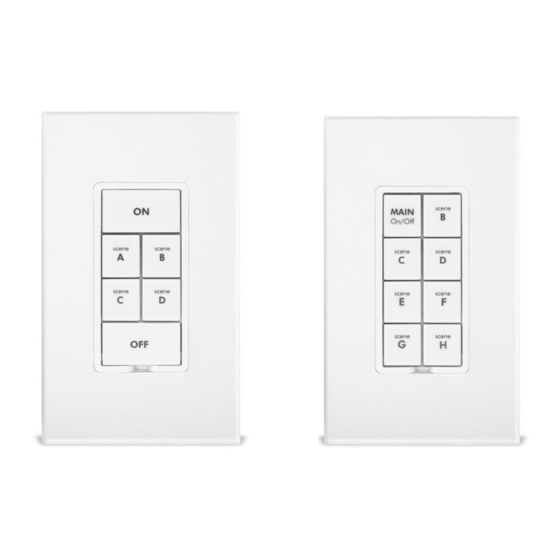
INSTEON KeypadLinc Dimmer User’s Guide Changing to Six Button or Eight Button Plate • In the six button mode, the six button plate provides a dedicated load ON button at the top of the switch, a dedicated load OFF button at the bottom, and four programmable secondary buttons between the ON and OFF button. - Page 8 INSTEON KeypadLinc Dimmer User’s Guide Installing KeypadLinc Dimmer 1. For best INSTEON Network performance, be sure you have properly installed at least two Access Point Modules. 2. At the circuit breaker or fuse panel, disconnect the power for all of the circuits in the switch junction box.
-
Page 9: Installing Keypadlinc Dimmer In A Multi-Way Circuit
INSTEON KeypadLinc Dimmer User’s Guide Installing KeypadLinc Dimmer in a Multi-Way Circuit Understanding Multi-Way Circuits If more than one switch controls a single set of lights (called a LOAD), the switches are part of a multi-way circuit. A 3-way circuit uses two switches to control a LOAD; a 4-way circuit uses three switches, and so forth. - Page 10 Secondaries, are not connected to the LOAD, but only to the power line (via the LINE and NEUTRAL). All of the KeypadLinc Dimmers can communicate with one another using INSTEON networking on the power line. After wiring in the KeypadLinc Dimmers, you create the virtual multi-way circuit by setting up all of the KeypadLinc Dimmers to control each other (see HOW TO SET UP KEYPADLINC DIMMER TO REMOTELY CONTROL AN INSTEON DEVICE, below).
- Page 11 LINE wire that you found, the black TRAVELER, and the Black LINE wire on KeypadLinc Dimmer all together with a single wire nut. If another type of INSTEON or X10 device is to be installed as the secondary switch, installation is likely as described above, but you should verify the installation instructions specific to that device.
- Page 12 INSTEON KeypadLinc Dimmer User’s Guide 3. Cap the other TRAVELER house wire. The other TRAVELER wire, usually red, will not be used, so put a wire nut on the end of it. 4. Cap the red LOAD wire from the KeypadLinc Secondary. Put a wire nut on the end of the KeypadLinc Secondary’s LOAD wire to ensure that it won’t connect to anything.
- Page 13 INSTEON KeypadLinc Dimmer User’s Guide 6. Connect the KeypadLinc Secondary’s GROUND Wire. Connect the bare copper GROUND wire to the other GROUND wires in the junction box. 7. Install Additional KeypadLinc Secondaries. If you have a four-way or greater switching circuit, see Special Treatment for Four- or More-Way Circuits at the end of this section.
- Page 14 INSTEON KeypadLinc Dimmer User’s Guide 10. Cap the other TRAVELER wire. The other TRAVELER wire, usually red, will not be used, so put a wire nut on the end of it. 11. Connect the KeypadLinc Primary’s LOAD Wire. Use a wire nut to connect the LOAD wire, usually red, to the KeypadLinc Primary’s red LOAD wire.
-
Page 15: Configure For Six Or Eight Button Operation
INSTEON KeypadLinc Dimmer User’s Guide Configure For Six or Eight Button Operation • To change your six button KeypadLinc to eight button mode, attach the eight button plate to KeypadLinc Dimmer. Gently pull the SET Button at the bottom of the switch out as far as it will go (about 1/8”) and wait 10 seconds. -
Page 16: How To Set Up Keypadlinc Dimmer To Remotely Control An Insteon Device
Any accidental button press will exit Linking Mode early. 2. Select your INSTEON Device from the list below and follow the linking method for that Device. You have about 4 minutes to perform this step before KeypadLinc Dimmer’s Linking Mode times out automatically. -
Page 17: Unlinking A Controlled Insteon Device From Keypadlinc Dimmer
10 seconds until the controlled light flashes again. 3. Follow the same method given above that you used to link your INSTEON Device to unlink it. On most INSTEON Devices, you just push an ON Button for 10 seconds or a SET Button for 3 seconds. -
Page 18: How To Set Up Keypadlinc Dimmer To Be Remotely Controlled By An Insteon Controller
Guide for detailed instructions on how to properly install it and link it to KeypadLinc Dimmer. The following will work for the most common INSTEON Controllers. 1. Select your INSTEON Controller from the list below and follow the method shown to put it into Linking Mode. -
Page 19: Unlinking Keypadlinc Dimmer From An Insteon Controller
Unlinking KeypadLinc Dimmer from an INSTEON Controller If you are no longer going to control a KeypadLinc Dimmer with an INSTEON Controller, it is very important that you unlink it, because otherwise the controller will retry any commands intended for the unused KeypadLinc Dimmer, thus slowing down your system. -
Page 20: How To Set Up On-Levels And Ramp Rates
Local On-Level and Ramp Rate values apply when you tap the On Button or Off Button on KeypadLinc Dimmer itself. Remote-Controlled On-Level and Ramp Rate values apply when another INSTEON Controller tells KeypadLinc Dimmer to turn on or turn off. KeypadLinc Dimmer stores separate On-Levels and Ramp Rates for each button on each Controller that it is linked to. -
Page 21: Setting The Ramp Rate
On-Level and try the Ramp Rate setting again. Locking In a Remote-Controlled On-Level and Ramp Rate Whenever you link an INSTEON Controller to KeypadLinc Dimmer, the current On-Level and Ramp Rate values are stored in KeypadLinc Dimmer’s memory. So, locking in a remote-controlled On-Level and Ramp Rate is really just the same as linking. -
Page 22: How To Cross-Link More Than One Keypadlinc Dimmer
Note: If you intend on setting a ramp rate or ON level; this should be done on each switch prior to cross- linking them. Please refer to the section above on How to set up KeypadLinc Dimmer to remotely control an INSTEON device for instructions on linking switches. 1. Link Primary Switch to Secondary Switch. -
Page 23: Advanced Features Of Keypadlinc Dimmer
Controller first. See Unlinking KeypadLinc Dimmer from an INSTEON Controller, above. 4. If you are using KeypadLinc Dimmer to control any INSTEON Devices other than the light it is wired to, unlink those Devices from KeypadLinc Dimmer. See Unlinking a Controlled INSTEON Device from KeypadLinc Dimmer, above. -
Page 24: Grouping Buttons
KeypadLinc can be grouped with the exception of the A button when in KeypadLinc’s 8-button mode. Programming groups is much more involved than most INSTEON device programming. Following are steps for creating a two button group. When creating groups with more than two buttons, we recommended you contact Smarthome Technical Support for assistance if you have any problems. - Page 25 INSTEON KeypadLinc Dimmer User’s Guide • If in eight button mode: Simultaneously press the “C” and “F” buttons and then release. Adjust the Local load brightness level. (Hold down KeypadLinc Dimmer’s On/Off Button(s) to brighten or dim the controlled light.) Simultaneously press the “C”...
-
Page 26: X10 Programming Options
INSTEON KeypadLinc Dimmer User’s Guide X10 PROGRAMMING OPTIONS KeypadLinc Dimmer is backward-compatible with X10, meaning that it can respond to X10 commands from an X10 Controller and it can send X10 commands to X10 devices. However, to operate KeypadLinc Dimmer in X10 mode, you must first set up an X10 Primary Address. As it ships from... -
Page 27: Setting The X10 On-Level And X10 Ramp Rate For The X10 Primary Address
INSTEON KeypadLinc Dimmer User’s Guide Setting the X10 On-Level and X10 Ramp Rate for the X10 Primary Address When an X10 Controller sends an X10 ON or X10 OFF NOTE command KeypadLinc Dimmer’s Primary Address, the Local On-Level and Local Ramp Rate If you want an X10 On-Level and Ramp apply. -
Page 28: Advanced X10 Programming Options
INSTEON KeypadLinc Dimmer User’s Guide ADVANCED X10 PROGRAMMING OPTIONS You can remotely set up X10 Scene Addresses as well as On-Levels and Ramp Rates using an X10 Controller capable of sending an X10 address (house code and unit code) without sending X10 ON or OFF commands. -
Page 29: About X10 Scene Address Programming
INSTEON KeypadLinc Dimmer User’s Guide Bright- Ramp Bright- Ramp Bright- Ramp ness Rate in ness Rate in ness Rate in Level Seconds Level Seconds Level Minutes 100% 19.0 21.5 23.5 4. Send the following X10 Address sequence to lock in the new Ramp Rate: 5. -
Page 30: Remotely Setting The Ramp Rate For An X10 Scene Address
INSTEON KeypadLinc Dimmer User’s Guide 3. Send an X10 ON or OFF command. 4. Send the following X10 Address sequence: 5. Send the X10 Scene Address (house code and unit code) that is to be removed. 6. KeypadLinc Dimmer will flash the light it is wired to, indicating that the X10 Scene Address has been removed. -
Page 31: How To Use Keypadlinc Dimmer
INSTEON KeypadLinc Dimmer User’s Guide HOW TO USE KEYPADLINC DIMMER Using the Buttons The On Button makes your light go ON and the Off Button makes your light go OFF. • Tap the On Button to make your light go at the Local Ramp Rate from whatever brightness it currently has to the Local On-Level brightness. -
Page 32: Changing Keypadlinc Dimmer Buttons
INSTEON KeypadLinc Dimmer User’s Guide Changing KeypadLinc Dimmer Buttons Use custom etched button to make your KeypadLinc your own The KeypadLinc button may be changed so you can customize its appearance. While we encourage you to customize your KeypadLinc, please be gentle in removing the keys. The buttons on the KeypadLinc require extra special care in removing the keycaps. -
Page 33: About Insteon
RF-only INSTEON devices, such as handheld controllers. In addition, two Access Points provide a wireless path for INSTEON signals to travel between the two separate electrical circuits, called power-line phases, found in most homes. Without a reliable method for coupling opposite power-line phases, some parts of your home may receive INSTEON signals intermittently. -
Page 34: About Insteon And X10
How INSTEON May Affect X10 If your existing X10 devices seem to be working less reliably after installing INSTEON devices, remember that INSTEON devices can absorb X10 signals just as X10 devices do, and that INSTEON devices do not repeat X10 signals. -
Page 35: Troubleshooting
Other modules are absorbing Move the other modules or the Controller to another the signal. outlet. Add new INSTEON devices or move around existing My KeypadLinc Dimmer INSTEON devices. All INSTEON devices act as is not linking to or INSTEON Network repeaters. - Page 36 INSTEON Controller so it doesn’t send both INSTEON brightness. and X10 commands. If the INSTEON Device is still available, unlink it from When I press a button on You may have removed an KeypadLinc Dimmer by following the directions in the...
-
Page 37: Specifications
INSTEON only, X10 only, INSTEON and X10 Combo Mode Combo Mode Message Order INSTEON, X10, INSTEON cleanup Multi-Way Circuit Support One KeypadLinc Dimmer controls load, Cross-Link any number of KeypadLinc Dimmers or other INSTEON Controllers Setup Memory Non-volatile EEPROM INSTEON Features INSTEON Addresses... - Page 38 INSTEON KeypadLinc Dimmer User’s Guide Mechanical Button Type 6 or 8 mechanical momentary contact type buttons Button Appearance Transparent plastic caps, holding preprinted or custom button labels, with LED backlighting Wire Nuts 3 included Mounting Mounts in single or multiple-ganged junction box.
-
Page 39: Certification
INSTEON, Plug-n-Tap, ControLinc, TesterLinc, SignaLinc, LampLinc, ToggleLinc, BoosterLinc, RemoteLinc, ApplianceLinc, KeypadLinc, FilterLinc, ProbeLinc, SwitchLinc, TempLinc, IR Linc and SmarthomeLive are trademarks of SmartLabs, Inc. INSTEON networking technology is covered by pending U.S. and foreign patents © Copyright 2008 SmartLabs, Inc., 16542 Millikan Ave., Irvine, CA 92606-5027, 800-243-8018, www.smarthome.com...
Need help?
Do you have a question about the 2486DWH6 and is the answer not in the manual?
Questions and answers