INSTEON 2457D2 Owner's Manual
Dimmer module
Hide thumbs
Also See for 2457D2:
- Owner's manual (19 pages) ,
- Quick start manual (8 pages) ,
- Quick start manual (8 pages)

Subscribe to Our Youtube Channel
Related Manuals for INSTEON 2457D2


Summary of Contents for INSTEON 2457D2
- Page 1 ® ® INSTEON Dimmer Module 2457D2 INSTEON Dimmer Module 2457D2 Owner’s Manual Owner’s Manual...
-
Page 2: Table Of Contents
Responders Controller-Only Responder-Only Grouping Devices Use Cross Linking INSTEON Hub Linking to the INSTEON Hub Manual Linking Linking with a Single-Button Controller Linking with a Multi-Button Controller Multi-Linking or Making a Scene Unlinking from a Single-Button Controller Unlinking from a Multi-Button Controller... -
Page 3: Getting Started
Getting Started Getting Started Everything you need to quickly get up and running. Everything you need to quickly get up and running. -
Page 4: Insteon Dimmer Module
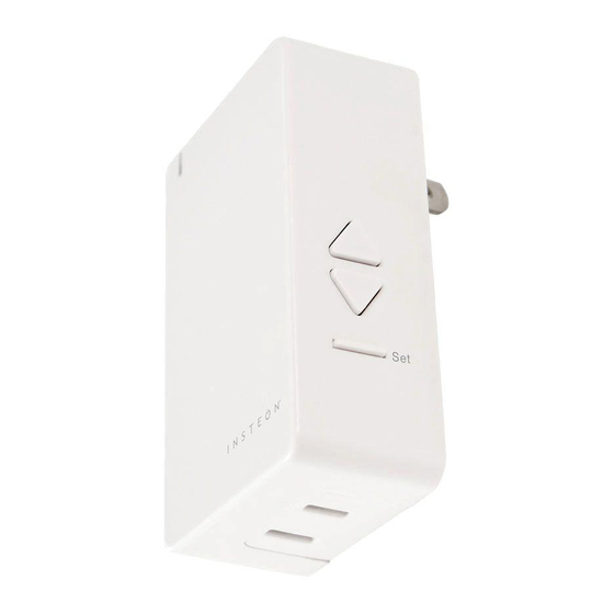
INSTEON Dimmer Module Device Overview Buttons Status LED Tap to turn on Double-tap to turn on instantly Press and hold to brighten Tap to turn off Double-tap to turn off instantly Press and hold to dim Set Button See sections on Basic Linking and Local Programming for set button ®... -
Page 5: Insteon Links
INSTEON Links INSTEON Links INSTEON devices can stand alone and function as a local switch or INSTEON devices can stand alone and function as a local switch or dimmer, but their real power comes when they are connected together to dimmer, but their real power comes when they are connected together to form a control system. -
Page 6: Understanding Linking
Switch B cannot turn Switch A on or off. to 75% brightness. Controllers Responders INSTEON devices that can turn other devices INSTEON devices that receive the command of a on or off are called controllers. controller are called responders. ® Neutral ®... -
Page 7: Controller-Only
Understanding Linking Controller-Only Responder-Only Some devices like sensors can only control Some devices cannot control other devices; other devices. these devices only receive INSTEON commands. ® Motion Sensor Dimmer Switch LED Bulb Dimmer Switch The Motion Sensor will turn on the Switch... -
Page 8: Insteon Hub
INSTEON Hub INSTEON Hub The INSTEON Hub allows you to configure your device, customize its The INSTEON Hub allows you to configure your device, customize its properties, create scenes and more, all from your smartphone or tablet. properties, create scenes and more, all from your smartphone or tablet. -
Page 9: Linking To The Insteon Hub
Linking to the INSTEON Hub Tap the Add button. From Rooms, navigate to All Devices. Rooms All Devices All Devices Check-In Favorites Back Door Bathroom Bedroom Bathroom Bedroom Hallway Font Door Garage Door Garage Light Kitchen Living Room Outside Motion Sensor Outside Lights 72º... -
Page 10: Manual Linking
Manual Linking Manual Linking When not using a central controller like the INSTEON Hub, INSTEON When not using a central controller like the INSTEON Hub, INSTEON devices can be configured and linked manually on a device-to-device devices can be configured and linked manually on a device-to-device basis. -
Page 11: Linking With A Single-Button Controller
Linking with a Single-Button Controller Manual Linking Only Make sure the Dimmer Module is On your INSTEON controller, press On and then press and hold the and hold the set button until the Dimmer Module’s set button until device beeps. -
Page 12: Linking With A Multi-Button Controller
Linking with a Multi-Button Controller Manual Linking Only Make sure the Dimmer Module is On your INSTEON controller, tap On and then press and hold the the desired control button and Dimmer Module’s set button until then press and hold the set button the device double-beeps. -
Page 13: Multi-Linking Or Making A Scene
Multi-Linking or Making a Scene Manual Linking Only Adjust your scene members to On your INSTEON controller, press their desired state: on, off, or and hold the set button until the device beeps, then tap the set brightness level if dimming. -
Page 14: Unlinking From A Single-Button Controller
Unlinking from a Single-Button Controller Manual Linking Only Press and hold the set button On your INSTEON controller, press again until the device beeps. and hold the set button until the device beeps. Press and hold the Dimmer Module’s set button until the device double-beeps. -
Page 15: Unlinking From A Multi-Button Controller
Unlinking from a Multi-Button Controller Manual Linking Only On your INSTEON controller, tap Press and hold the set button the desired control button and again until the device beeps. then press and hold the set button until the device beeps. -
Page 16: Multi-Unlinking Or Removing A Scene
Press and hold the set button again, then tap the set button. ® Tap the set button on your INSTEON controller to exit Multi- Unlinking mode. ® ® ® Your INSTEON controller will no longer control your INSTEON responders. -
Page 17: Local Programming
Local Programming Local Programming Use the local programming to set local on-level, ramp rates and even Use local programming to set local on-level, ramp rates and even perform perform a factory reset. a factory reset. -
Page 18: About Local Programming
INSTEON device or four minutes have elapsed without linking. Multi- Allows the removal of multiple links from the INSTEON device. The device will stay in unlinking mode for 4 Unlinking minutes or until the device’s set button is tapped. -
Page 20: Software-Only Features
Software-Only Features Software-Only Features Most INSTEON devices contain features that can only be enabled, Most INSTEON devices contain features that can only be enabled, disabled or modified using INSTEON control software such as HouseLinc disabled or modified using INSTEON control software such as HouseLinc and an INSTEON PowerLine Modem or the INSTEON Hub. -
Page 21: Beep On Button Press
Error Blink The Dimmer Module LED will blink if it detects The Dimmer Module LED will blink red once if INSTEON communication. By default, this one or more responders do not acknowledge feature is disabled. a message and will blink green once if all responders successfully acknowledge a message. -
Page 22: X10 Support
X10 Support X10 Support Your INSTEON device features backwards compatibility with legacy X10 Your INSTEON device features backwards compatibility with legacy X10 devices and can respond to X10 powerline messages. devices and can respond to X10 powerline messages. -
Page 23: Setting The X10 Address
Setting the X10 Address Using an X10 controller, send the Press and hold the set button desired X10 address followed by on your Dimmer Module until the the On command three times. device beeps. ® ® Your Dimmer Module will now respond to the set X10 address. -
Page 24: Removing The X10 Address
Dimmer Module until the device beeps. ® ® Using an X10 controller, send the programmed X10 address followed by the On command three times. ® Your INSTEON controller will no longer control your Dimmer Module. -
Page 25: Appendix
Appendix Appendix Everything else you might need to know about your INSTEON product. Everything else you might need to know about your INSTEON product. - Page 26 / Unlinking simultaneously, without laborious set button presses. When in linking or unlinking mode, an INSTEON device will continue to link to other devices until the set button is tapped or four minutes have elapsed, whichever occurs first. Factory Reset A process that erases all stored links and reconfigures the device to factory defaults.
-
Page 27: Specifications
Brand: INSTEON FCC ID SBP2475D2A Industry Canada 5202A-2475D2A Manufacturer Product No.: 2475D2 Patent No.: Protected under US and Foreign Patents (see www.insteon.com/ patents) UPC: 813922010183 Warranty: 2 years, limited Operation Audio Alert Beeper, can be enabled/disabled through software Operation Modes... - Page 28 Maximum Scene Memberships Multi-Link Support Multi-Unlink Support RF Beacon Radio Frequency 915.0 MHz Radio Frequency Range 150 feet Scene Commands Supported as Controller Fast-On Fast-Off Begin Brighten Begin Dim End Brighten End Dim Scene Commands Supported as Responder Fast-On Fast-Off Begin Brighten Begin Dim End Brighten...
- Page 29 Electrical Controlled Outlet Yes, ungrounded polarized. NEMA 1-15 type Hardwired Remote Control Load Types Plug-in incandescent lighting sources Maximum Load 300 Watts Minimum Load 5 Watts Pass-through Outlet Power Consumption <0.75 Watts Supply Voltage 120 Volts AC ± 10%, 60 Hertz, single phase Surge Resistance Surges over 1,000 volts X10 Features (Powerline Only)
-
Page 30: Troubleshooting
If the outlet works and the connected lamp can be toggled, use software or the Local Programming Flowchart to change the behavior of the status LED. The status LED brightness can be dimmed to the point that it appears off. The INSTEON Hub and other central controller software allow setting of this device property. - Page 31 The connected lamp turned on by itself There must be a device in your INSTEON network that is unexpectedly linked to the Dimmer Module. If you have given your device an X10 address, powerline noise may be triggering the INSTEON device.
-
Page 32: Certifications And Warnings
To minimize heat buildup, ensure the area surrounding this product is as clear of clutter as possible. • Each INSTEON product is assigned a unique INSTEON I.D., which is printed on the product’s label. • To reduce the risk of overheating and possible damage to other equipment, do not use this product to control loads in excess of the specified maximum(s) or, install in locations with electricity specifications which are outside of the product’s specifications. -
Page 33: Product Warranty
You may also have other legal rights that may vary from state to state. Protected under U.S. and foreign patents (see www.insteon.com/patents) © Copyright 2014 INSTEON Rev 01.17.14...
Need help?
Do you have a question about the 2457D2 and is the answer not in the manual?
Questions and answers