
Related Manuals for INSTEON 2453-222


Summary of Contents for INSTEON 2453-222
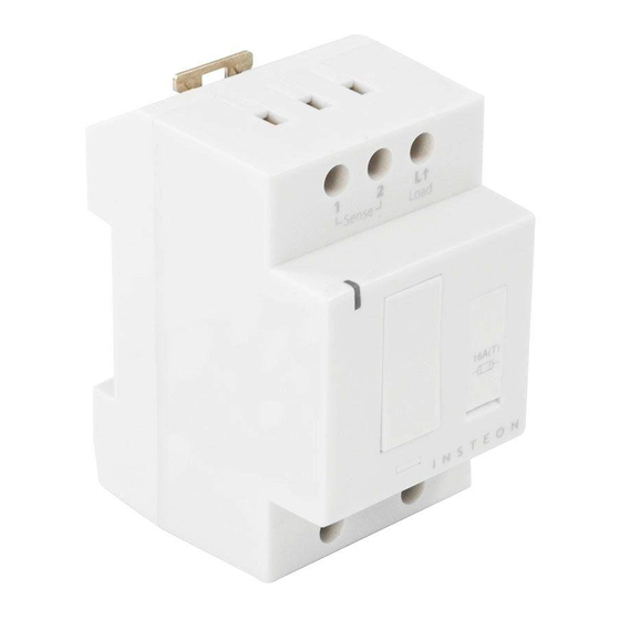
- Page 1 DIN Rail On/Off Owner’s Manual 2453-222 (US) 2453-422 (EU) 2453-522 (AUS/NZ) Page 1 of 16 2453-222/2453-422/2453-522 - Rev: 1/21/2014 7:51 AM...
-
Page 2: Table Of Contents
Adjust Local Settings..............................6 Change LED Brightness .............................. 6 Error Blink ..................................7 INSTEON Setup ................................7 INSTEON Controllers, Responders and Links ......................7 Make DIN Rail a Responder ............................7 Make DIN Rail a Controller ............................7 Groups ..................................8 Scenes .................................. -
Page 3: About Din Rail On/Off
To minimize heat buildup, ensure the area surrounding this product is as clear of clutter as possible. Each INSTEON product is assigned a unique INSTEON I.D., which is printed on the product’s label. To reduce the risk of overheating and possible damage to other equipment, do not use this product to control loads in excess of the specified maximum(s) or, install in locations with electricity specifications which are outside of the product’s... -
Page 4: Identify Switch Type
4) Use a voltage meter to identify the fixture’s line, load and neutral wires, then turn off breaker/fuse again 5) For reference, write down the INSTEON I.D. (on the side of the module) and the load it is controlling 6) Snap module onto DIN rail. (If installing next to another module, allow 3/4" (2 cm) between modules for heat dissipation.) -
Page 5: Switch Operation Mode
DIN Rail module will beep LED will start double-blinking red 6) Press and hold set button until it double-beeps LED will stop blinking 3-way toggle mode is now disabled (or re-enabled) Page 5 of 16 2453-222/2453-422/2453-522 - Rev: 1/21/2014 7:51 AM... -
Page 6: Local Control Operations
LED will start blinking green 2) Press and hold set button until it beeps a second time LED will start blinking red 3) Press and hold set button until it beeps a third time Page 6 of 16 2453-222/2453-422/2453-522 - Rev: 1/21/2014 7:51 AM... -
Page 7: Error Blink
The link just created is one way. See “Make DIN Rail a Controller” to add another link to keep the two products in synch, or see “Groups” section. Make DIN Rail a Controller Use DIN Rail to control other INSTEON devices: Press and hold DIN Rail set button until it beeps DIN Rail LED will start blinking green... -
Page 8: Groups
Make DIN Rail a Controller of Multiple Responders 1) Press and hold DIN Rail set button until it beeps LED will start blinking green 2) Tap DIN Rail set button LED will start double-blinking green Page 8 of 16 2453-222/2453-422/2453-522 - Rev: 1/21/2014 7:51 AM... -
Page 9: Remove Din Rail As A Controller (Unlink)
3) Press and hold DIN Rail set button until it beeps a second time LED will start blinking red 4) Press and hold DIN Rail set button until it beeps a third time LED will start blinking green Page 9 of 16 2453-222/2453-422/2453-522 - Rev: 1/21/2014 7:51 AM... -
Page 10: X10 Setup
2453-222 Manufacturer product number 2453-422 AUS/NZ 2453-522 813922012828 813922012835 AUS/NZ 813922012842 Warranty 2 years, limited INSTEON INSTEON powerline mesh repeater INSTEON RF mesh repeater INSTEON controller INSTEON responder Maximum links/scenes Page 10 of 16 2453-222/2453-422/2453-522 - Rev: 1/21/2014 7:51 AM... - Page 11 Case color White Set button Plastic UV stabilized polycarbonate Beeper Beep on button press Optional (off by default) 1, RGB Dimensions 3.14"H x 2.05"W x 2.48"D (80mm x 52mm x 63mm) Page 11 of 16 2453-222/2453-422/2453-522 - Rev: 1/21/2014 7:51 AM...
-
Page 12: Troubleshooting
DIN Rail is not getting power tight and no bare wires are exposed won't control my light Check the light fixture to ensure all connections are tight and no bare wires are exposed Page 12 of 16 2453-222/2453-422/2453-522 - Rev: 1/21/2014 7:51 AM... - Page 13 Connect power to the device DIN Rail, it takes a long DIN Rail is trying to control a If the INSTEON device is still available, remove it from time for other INSTEON scene responder that is not DIN Rail and then re-add it...
-
Page 14: Phase Bridge Detect Beacon/Rf Range Test
2- and 3- phase circuits. The phase bridge detect beacon can also be used as an RF range test to see if your devices are within communication range. You will need at least one other INSTEON dual-band device installed. -
Page 15: Certification And Warranty
The repair, replacement, or refund that is provided for above shall be the full extent of Seller’s liability with respect to this product. For repair or replacement during the warranty period, call INSTEON at 866-243-8022 with the Model # and Revision # of the device... -
Page 16: Limitations
You may also have other legal rights that may vary from state to state. U.S Patent No. 7,345,998, International patents pending © Copyright 2011 INSTEON, 16542 Millikan Ave., Irvine, CA 92606, 866-243-8022, www.insteon.com Page 16 of 16...
Need help?
Do you have a question about the 2453-222 and is the answer not in the manual?
Questions and answers