
Related Manuals for INSTEON SWITCHLINC 2476D


Summary of Contents for INSTEON SWITCHLINC 2476D
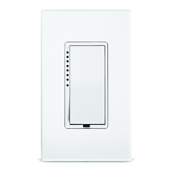
- Page 1 ™ INSTEON ™ SwitchLinc V2 INSTEON Dimmer Switch For models: #2476D SwitchLinc V2 Dimmer...
-
Page 2: Table Of Contents
Installing SwitchLinc Dimmer ... 7 Installing SwitchLinc Dimmer in a Multi-Way Circuit ... 8 HOW TO SET UP SWITCHLINC DIMMER TO REMOTELY CONTROL AN INSTEON DEVICE ... 14 Linking SwitchLinc Dimmer to a Controlled INSTEON Device... 14 Unlinking a Controlled INSTEON Device from SwitchLinc Dimmer ... 15 Creating an INSTEON Scene... - Page 3 ABOUT INSTEON ... 29 Understanding Why an INSTEON Network Is Reliable... 29 Further Enhancing Reliability ... 29 Using Smarthome’s SignaLinc RF to Upgrade Your INSTEON Network ... 29 About INSTEON and X10... 30 TROUBLESHOOTING... 31 SPECIFICATIONS ... 33 SwitchLinc Dimmer Specifications ... 33 Certification...
-
Page 4: About Insteon Switchlinc Dimmer
INSTEON is a simple, reliable, and affordable breakthrough in home control. Simple, because Plug-n- Tap™ setup is a breeze, and there are no wires to add – INSTEON uses existing powerline wiring as well as radio-frequency for communication. Reliable, because every INSTEON device is a two-way repeater. -
Page 5: How To Install Switchlinc Dimmer
Linc Dimmer, it may be necessary to identify the wires ins for sure which wire is the LINE (sometimes called HOT) can reduce the guesswork when installing a single switch, and it is absolutely necessary when working with multi-way lighting circuits. A voltmeter is ideal for this application. Many of the digital models can also read current so you can measure how much power is being drawn by the switch’s load. -
Page 6: Preparing To Install Switchlinc Dimmer
NEUTRAL electrical wire (usually white). If you are replacing a standard mechanical switch with SwitchLinc Dimmer, the switch you are replacing will normally not have a connection to the neutral wire. However, most junction boxes will contain a NEUTRAL wire that you can connect SwitchLinc Dimmer to. -
Page 7: Installing Switchlinc Dimmer
INSTEON SwitchLinc V2 Dimmer User’s Guide Installing SwitchLinc Dimmer 1. For best INSTEON Network performance, be sure you have properly installed at least two SignaLinc RF Signal Enhancers. 2. At the circuit breaker or fuse panel, disconnect the power for all of the circuits in the switch junction box. -
Page 8: Installing Switchlinc Dimmer In A Multi-Way Circuit
Understanding Multi-Way Circuits If more than one switch controls a single set of lights (called a LOAD), the switches are part of a multi-way circuit. A 3-way circuit uses two switches to control a LOAD, a 4-way circuit uses three switches, and so forth. - Page 9 LOAD, but only to the powerline (by being wired to the LINE and NEUTRAL). All of the SwitchLinc Dimmers can communicate with one another using INSTEON networking on the powerline. After wiring in the SwitchLinc Dimmers, you create the virtual multi-way circuit by setting up all of the SwitchLinc Dimmers to control each other (see HOW TO SET UP SWITCHLINC DIMMER TO REMOTELY CONTROL AN INSTEON DEVICE, below).
- Page 10 Step-by-Step Instructions for Installing Multi-Way SwitchLinc Dimmers When replacing a three-way mechanical switch, each switch will have three wires connected to it from the wall box. Four-way or greater circuits will have four wires connected to the switches in the center of the circuit.
- Page 11 INSTEON SwitchLinc V2 Dimmer User’s Guide 3. Cap the other TRAVELER wire. The other TRAVELER wire, usually red, will not be used, so put a wire nut on the end of it. 4. Cap the red LOAD wire from the SwitchLinc Secondary.
- Page 12 8. Identify the Wires for the SwitchLinc Primary. The SwitchLinc Primary is the SwitchLinc Dimmer that will actually control the LOAD. In the remaining junction box where you will install the SwitchLinc Primary, find the wire that carries power from the switch to the lights. This wire, called the LOAD wire, is commonly red.
- Page 13 Two of the wires are TRAVELERS from the preceding switch and the other two are TRAVELERS to the next switch in the chain. You will be converting the black TRAVELER wires to LINE wires and replacing the old four-wire switches with SwitchLinc Secondaries.
-
Page 14: How To Set Up Switchlinc Dimmer To Remotely Control An Insteon Device
Any paddle press will exit Linking Mode early. 2. Select your INSTEON Device from the list below and follow the linking method for that Device. You have about 4 minutes to perform this step before SwitchLinc Dimmer’s Linking Mode times out automatically. -
Page 15: Unlinking A Controlled Insteon Device From Switchlinc Dimmer
3. Follow the same method given above that you used to link your INSTEON Device to unlink it. On most INSTEON Devices, you just push an ON Button for 10 seconds or a SET Button for 3 seconds. -
Page 16: How To Set Up Switchlinc Dimmer To Be Remotely Controlled By An Insteon Controller
Guide for detailed instructions on how to properly install it and link it to SwitchLinc Dimmer. The following will work for the most common INSTEON Controllers. 1. Select your INSTEON Controller from the list below and follow the method shown to put it into Linking Mode. -
Page 17: Unlinking Switchlinc Dimmer From An Insteon Controller
Unlinking SwitchLinc Dimmer from an INSTEON Controller If you are no longer going to control a SwitchLinc Dimmer with an INSTEON Controller, it is very important that you unlink it, because otherwise the controller will retry any commands intended for the unused SwitchLinc Dimmer, thus slowing down your system. -
Page 18: How To Set Up On-Levels And Ramp Rates
Local On-Level and Ramp Rate values apply when you tap the Paddle Top or Paddle Bottom on SwitchLinc Dimmer itself. Remote-Controlled On-Level and Ramp Rate values apply when another INSTEON Controller tells SwitchLinc Dimmer to turn on or turn off. SwitchLinc Dimmer stores separate On-Levels and Ramp Rates for each button on each Controller that it is linked to. -
Page 19: Setting The Ramp Rate
To lock in the current On-Level and Ramp Rate as the Local On-Level and Ramp Rate, all you have to do is not link SwitchLinc Dimmer to an INSTEON Controller for four minutes. After the four-minute timeout, the current On-Level and current Ramp Rate will be permanently locked in as the Local On-Level and Local Ramp Rate. -
Page 20: Advanced Features Of Switchlinc Dimmer
Controller first. See Unlinking SwitchLinc Dimmer from an INSTEON Controller, above. 2. If you are using SwitchLinc Dimmer to control any INSTEON Devices other than the light it is wired to, unlink those Devices from SwitchLinc Dimmer. See Unlinking a Controlled INSTEON Device from SwitchLinc Dimmer, above. -
Page 21: X10 Programming Options
INSTEON SwitchLinc V2 Dimmer User’s Guide X10 PROGRAMMING OPTIONS SwitchLinc Dimmer is X10 ready, meaning that it can respond to X10 commands from an X10 Controller and it can send X10 commands to X10 devices. However, to operate SwitchLinc Dimmer in X10 mode, you must first set up an X10 Primary Address. -
Page 22: Setting The X10 On-Level And X10 Ramp Rate For The X10 Primary Address
INSTEON SwitchLinc V2 Dimmer User’s Guide Setting the X10 On-Level and X10 Ramp Rate for the X10 Primary Address When an X10 Controller sends an X10 ON or X10 OFF command to SwitchLinc Dimmer’s Primary X10 Address, the Local On-Level and Local Ramp Rate apply. In other words, SwitchLinc Dimmer acts the same way as it would if you manually tapped its Paddle Top or Paddle Bottom. -
Page 23: Advanced X10 Programming Options
INSTEON SwitchLinc V2 Dimmer User’s Guide ADVANCED X10 PROGRAMMING OPTIONS You can remotely set up X10 Scene Addresses as well as On-Levels and Ramp Rates using an X10 Controller capable of sending an X10 address (house code and unit code) without sending X10 ON or OFF commands. -
Page 24: About X10 Scene Address Programming
INSTEON SwitchLinc V2 Dimmer User’s Guide Bright- Ramp ness Rate in Level Seconds 100% 19.0 21.5 23.5 4. Send the following X10 Address sequence to lock in the new Ramp Rate: 5. SwitchLinc Dimmer will flash the light it is wired to and blink an LED in its LED Bar, indicating that the Ramp Rate has been set for the X10 Primary Address. -
Page 25: Remotely Setting The Ramp Rate For An X10 Scene Address
INSTEON SwitchLinc V2 Dimmer User’s Guide 3. Send an X10 ON or OFF command. 4. Send the following X10 Address sequence: 5. Send the X10 Scene Address (house code and unit code) that is to be removed. 6. SwitchLinc Dimmer will flash the light it is wired to and blink an LED in its LED Bar, indicating that the X10 Scene Address has been removed. -
Page 26: How To Use Switchlinc Dimmer
INSTEON SwitchLinc V2 Dimmer User’s Guide HOW TO USE SWITCHLINC DIMMER Using the Paddle The Paddle Top makes your light go ON and the Paddle Bottom makes your light go OFF. • Tap the Paddle Top to make your light go at the Local Ramp Rate from whatever brightness it currently has to the Local On-Level brightness. -
Page 27: Color Options For Switchlinc Dimmer
2. Remove the four Phillips screws that hold the paddle assembly to the metal frame. 3. Pull the entire paddle frame straight away from the switch. You may have to wiggle the bottom of the frame to get it free of the bottom SET Button. - Page 28 INSTEON SwitchLinc V2 Dimmer User’s Guide 5. Orient the new small light pipe with its protrusion facing toward the center of the frame and snap it into place. backwards or reversed, it will not click into place. Refer to the diagram.
-
Page 29: About Insteon
INSTEON device helps to support the overall network. To further ensure reliability, every INSTEON device confirms that it has received a command. If an INSTEON Controller does not receive this confirmation, it will automatically retransmit the command up to five times. -
Page 30: About Insteon And X10
INSTEON’s Effect on X10 If your existing X10 devices seem to be working less reliably after installing INSTEON devices, remember that INSTEON devices can absorb X10 signals just as X10 devices do, and that INSTEON devices do not repeat X10 signals. -
Page 31: Troubleshooting
Plugging the Controller directly into a wall outlet works best. Move the other modules or the Controller to another outlet. Add new INSTEON devices or move around existing INSTEON devices. All INSTEON devices act as INSTEON Network repeaters. Make sure you are not experiencing interference with older X10 BoosterLinc technology. - Page 32 Remove the X10 Address from the button on your INSTEON Controller so it doesn’t send both INSTEON and X10 commands. If the INSTEON Device is still available, unlink it from SwitchLinc Dimmer by following the directions in the section Unlinking a Controlled INSTEON Device from SwitchLinc Dimmer, above.
-
Page 33: Specifications
INSTEON only, X10 only, INSTEON and X10 Combo Mode INSTEON, X10, INSTEON cleanup One SwitchLinc Dimmer controls load, Cross-Link any number of SwitchLinc Dimmers or other INSTEON Controllers Non-volatile EEPROM 1 hard-coded out of 16,777,216 possible 417 out of 16,777,216 possible 131.65 KHz... - Page 34 Control 200 W less load for each immediately adjacent SwitchLinc Dimmer installed. For example, 600 W load control becomes 400 W with another dimmer to the immediate right or left. Use a triple-gang box with a mechanical switch in the center to avoid de-rating.
-
Page 35: Certification
You may also have other legal rights that may vary from state to state. INSTEON, Plug-n-Tap, ControLinc, TesterLinc, SignaLinc, LampLinc, ToggleLinc, BoosterLinc, ApplianceLinc, KeypadLinc, FilterLinc, ProbeLinc, SwitchLinc, TempLinc, IR Linc and SmarthomeLive are trademarks of Smarthome, Inc.
Need help?
Do you have a question about the SWITCHLINC 2476D and is the answer not in the manual?
Questions and answers