Advertisement
Quick Links
Download this manual
See also:
User Manual
Quick-Start Guide
SWITCHLINC DIMMER
SwitchLinc V2 Dimmer (#2476D & #2476DH)
N N e e e e d d H H e e l l p p ? ? F F o o r r a a s s s s i i s s t t a a n n c c e e c c a a l l l l y y o o u u r r f f r r i i e e n n d d l l y y
s s u u p p p p o o r r t t p p e e r r s s o o n n @ @ 8 8 6 6 6 6 - - 2 2 4 4 3 3 - - 8 8 0 0 1 1 8 8
U U s s i i n n g g S S w w i i t t c c h h L L i i n n c c D D i i m m m m e e r r s s i i n n V V i i r r t t u u a a l l M M u u l l t t i i - - W W a a y y C C i i r r c c u u i i t t s s
In a virtual multi-way circuit, only one SwitchLinc Dimmer, called the SwitchLinc Primary, actually controls the LOAD in the multi-way
circuit. Any additional SwitchLinc Dimmers, called SwitchLinc Secondaries, are not connected to the LOAD, but only to the powerline
(by being wired to the LINE and NEUTRAL). All of the SwitchLinc Dimmers can communicate with one another using INSTEON net-
working on the powerline. After wiring in the SwitchLinc Dimmers, you create the virtual multi-way circuit by setting up all of the
SwitchLinc Dimmers to control each other.
The diagram below shows how you convert a wired-in three-way circuit into a virtual three-way circuit using two SwitchLinc Dimmers.
Notice that one of the TRAVELER wires (number 1, the red one) is not used, so you will cap it off at both ends with a wire nut. The
other TRAVELER (number 2, the black one) you will convert to a LINE wire. In the junction box where the SwitchLinc Secondary is,
connect TRAVELER 2 to the existing LINE and also to the SwitchLinc Secondary's LINE wire. In the other junction box at the other end,
you will connect TRAVELER 2 to the SwitchLinc Primary's LINE wire.
The SwitchLinc Primary's LOAD wire gets connected to the actual lights that are being controlled. The LOAD wire for any SwitchLinc
Secondaries that you will be installing will not be connected to anything, so cap those LOAD wires off with a wire nut.
All SwitchLinc Dimmers, whether they are Primaries or Secondaries, must be connected to the NEUTRAL and to the GROUND wires.
Note that the switches you are replacing will not normally have a connection to the NEUTRAL wire. If there is no NEUTRAL wire in the
junction box, please consult an electrician or call SmartLabs Tech Support, 866-243-8018.
S S m m a a r r t t L L a a b b s s L L i i m m i i t t e e d d W W a a r r r r a a n n t t y y
SmartLabs warrants to the original consumer of this product that, for a period of two years from the date of purchase, this product will be free from defects in material and workmanship and will per-
form in substantial conformity to the description of the product in the owner's manual. This warranty shall not apply to defects or errors caused by misuse or neglect.
© © C C o o p p y y r r i i g g h h t t 2 2 0 0 0 0 7 7 S S m m a a r r t t L L a a b b s s , , 1 1 6 6 5 5 4 4 2 2 M M i i l l l l i i k k a a n n A A v v e e . . , , I I r r v v i i n n e e , , C C A A 9 9 2 2 6 6 0 0 6 6 - - 5 5 0 0 2 2 7 7
8 8 6 6 6 6 - - 2 2 4 4 3 3 - - 8 8 0 0 1 1 8 8 w w w w w w . . s s m m a a r r t t l l a a b b s s i i n n c c . . c c o o m m
Quick-Start Guide
SWITCHLINC DIMMER
For Models: SwitchLinc V2 Dimmer (#2476D) - 600 Watt
SwitchLinc V2 Dimmer (#2476DH) - 1000 Watt
Your new SwitchLinc Dimmer allows you to dim and remotely control any light in
your home at the touch of a button.
N N e e e e d d H H e e l l p p ? ? F F o o r r a a s s s s i i s s t t a a n n c c e e c c a a l l l l y y o o u u r r f f r r i i e e n n d d l l y y
s s u u p p p p o o r r t t p p e e r r s s o o n n @ @ 8 8 6 6 6 6 - - 2 2 4 4 3 3 - - 8 8 0 0 1 1 8 8
P P r r e e p p a a r r a a t t i i o o n n
I I n n s s t t a a l l l l a a t t i i o o n n s s h h o o u u l l d d b b e e p p e e r r f f o o r r m m e e d d o o n n l l y y b b y y a a q q u u a a l l i i f f i i e e d d e e l l e e c c t t r r i i c c i i a a n n o o r r b b y y a a h h o o m m e e o o w w n n e e r r w w h h o o i i s s f f a a m m i i l l i i a a r r a a n n d d c c o o m m f f o o r r t t a a b b l l e e w w i i t t h h e e l l e e c c t t r r i i c c a a l l c c i i r r - -
c c u u i i t t r r y y . . I I f f t t h h e e r r e e a a r r e e a a n n y y q q u u e e s s t t i i o o n n s s , , c c o o n n s s u u l l t t a a n n e e l l e e c c t t r r i i c c i i a a n n . . F F o o r r s s e e t t u u p p q q u u e e s s t t i i o o n n s s c c o o n n t t a a c c t t T T e e c c h h S S u u p p p p o o r r t t a a t t S S m m a a r r t t L L a a b b s s f f o o r r g g u u i i d d a a n n c c e e . .
T T o o o o l l s s y y o o u u w w i i l l l l n n e e e e d d : :
•A standard screwdriver
•A Phillips screwdriver
•A wire cutter/stripper
Installing Your SwitchLinc Dimmer
Step 1.
Be sure you have properly installed two AccessPoints (#2443).
Step 2.
At the circuit breaker or fuse panel, disconnect the power for all of the circuits in the switch junction box.
Step 3.
Remove the faceplate from the switch junction box, then unscrew the switch and pull it out from the junction box.
Step 4.
Disconnect the wires from the switch you are replacing and ensure you have 1/2" of bare wire on the ends.
Step 5.
If you are installing SwitchLinc into a t t w w o o - - w w a a y y c c i i r r c c u u i i t t (where one switch controls the load), follow the diagram below to
identify and connect the LINE, LOAD, NEUTRAL, and GROUND wires. If the colors of the wires do not match the
diagram, be sure you have identified the wires correctly before connecting them.
Step 6.
If you are installing into a m m u u l l t t i i - - w w a a y y c c i i r r c c u u i i t t (where more than one switch controls the load), consult the User's Guide.
Step 7.
Ensure that all wire connectors are firmly attached and that there is no exposed copper except for the GROUND wire.
Step 8.
Orient SwitchLinc Dimmer with the LED bar at the left, gently place it into the junction box, then screw it into place.
Step 9.
Turn the circuit breaker back on or re-install the fuse.
Step 10.
Test that SwitchLinc Dimmer is working properly by turning the light on and off.
Step 11.
Reinstall the faceplate.
rev. 062507
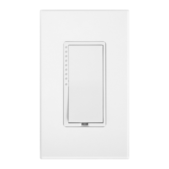
LED Bar
T T M M
Brightness
Indicator
•Optional: A #1 Phillips screwdriver to change the paddle color (sold separately)
•A voltage tester to identify wires inside the junction box
The NEUTRAL wire will not normally
be connected to the switch you are
replacing. If there is no NEUTRAL
wire in the junction box, please con-
SET Button
N N O O T T E E
sult an electrician or call
S S m m a a r r t t L L a a b b s s T T e e c c h h S S u u p p p p o o r r t t
8 8 6 6 6 6 - - 2 2 4 4 3 3 - - 8 8 0 0 1 1 8 8
Advertisement

Related Manuals for INSTEON 2476D


Summary of Contents for INSTEON 2476D
- Page 1 Any additional SwitchLinc Dimmers, called SwitchLinc Secondaries, are not connected to the LOAD, but only to the powerline (by being wired to the LINE and NEUTRAL). All of the SwitchLinc Dimmers can communicate with one another using INSTEON net- working on the powerline.
- Page 2 On your INSTEON controller p p r r e e s s s s a a n n d d h h o o l l d d the ON button of your choice for 10 seconds until the LED...
Need help?
Do you have a question about the 2476D and is the answer not in the manual?
Questions and answers