Datavideo SE-2800 Instruction Manual
Digital video switcher
Hide thumbs
Also See for SE-2800:
- Instruction manual (44 pages) ,
- Instruction manual (43 pages) ,
- Quick start manual (25 pages)

Related Manuals for Datavideo SE-2800


Summary of Contents for Datavideo SE-2800
- Page 1 .Digital Video Switcher. SE-2800 ( 8 / 12 CHANNEL ) Instruction Manual www.datavideo-tek.com...
-
Page 2: Table Of Contents
Keyboard Controls – Frame Store, AUX and Audio level ..........16 FS – Frame Store Button ..........................16 How to choose live video input or Frame Store ....................16 AUX Source Selection ...........................16 Audio Level..............................16 Menu Options ........................17 SE-2800 Video Layers ...................... 20... - Page 3 DSK Settings ..............................22 DSK Preset and DSK Program ........................22 Assigning an input to a DSK channel for keying ...................22 Example SE-2800 and CG-350 Set Up ......................23 Switcher configuration using a computer – SEConfig software ........24 Switcher tab..............................25 Profiles ...............................25 Settings tab ..............................25...
- Page 4 Further advice on the content of this manual or on the product can be obtained by contacting your local Datavideo Office or...
-
Page 5: Warnings And Precautions
7. This product should only be operated from the type of power source indicated on the marking label of the AC adapter. If you are not sure of the type of power available, consult your Datavideo dealer or your local power company. -
Page 6: Warranty
Certain parts with limited lifetime expectancy such as LCD Panels, DVD Drives, Hard Drives are only covered for the first 10,000 hours, or 1 year (whichever comes first). Any second year warranty claims must be made to your local Datavideo office or one of its authorized Distributors before the extended warranty expires. -
Page 7: Product Overview
Product Overview The SE-2800 is a cost effective HD/SD switcher featuring 8* or 12 channels. Thanks to a 2RU 19” form factor and 12V DC input the SE-2800 is ideal for use in portable rack units or outside broadcast vehicles. The SE-2800 produces superb 10 bit 4:2:2 broadcast quality pictures while also offering flexible input and output configurations. -
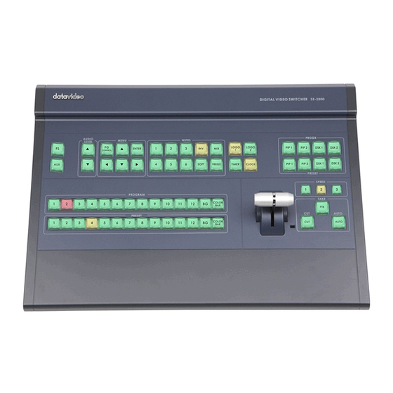
Page 8: Connections & Controls
24. 3pin XLR Audio Inputs 25. 3pin XLR Audio Outputs ** Please note inputs 9 to 12 are not present if you have purchased the eight channel SE-2800. Eight channel units can be upgraded to twelve inputs, please talk with your local dealer. -
Page 9: Rear Panel Connections
HD to SD resolution. ETHERNET PORT This RJ45 Ethernet port (18) is used to connect the SE-2800 to a PC for remote control, or to update the unit’s firmware, or to configure the switcher. See page 24 for more details. -
Page 10: Main Unit - Front Panel
Main Unit – Front Panel The front panel on the SE-2800 main unit has a grille for two airflow cooling fans. Please do not block or cover this grille as the unit may overheat. This grille should also be kept free of dust. The front panel can be removed by using the four thumbscrews. -
Page 11: Hdmi Multi-View
HDMI Multi-view SE-2800 Multi-view monitoring is available across one or two HDMI monitors (not supplied). These outputs can be used to monitor video and audio in a number of different configurations. For each set up, embedded audio level indication is available on all inputs and the Program window. -
Page 12: Keyboard Controls - Video Switching
Keyboard Controls – Video Switching Program and Preset rows The Program row of buttons is the active channel, this is the live output. The active channel will appear as the Program Output (PGM). You can switch or CUT from one video source to another directly on the Program row. You will see the multi view PGM output change as you press different keys along this top row of buttons. -
Page 13: Keyboard Controls - Video Transitions
Keyboard Controls – Video Transitions Transition Selection The SE-2800 features six user defined wipe buttons, an A/B dissolve or MIX button, an INV or Invert wipes button and a FREEZE button. All wipes can have an optional colour border applied. The wipe border width and colour are chosen within the menu system. -
Page 14: Keyboard Controls - Logo 1, Logo 2, Clock And Timer
Keyboard Controls – LOGO 1, LOGO 2, CLOCK and TIMER The SE-2800 has the ability to store six static logos and one dynamic logo. The logo files are transferred to the SE-2800 from a Windows PC using the Ethernet connection and the supplied SEConfig software. See page 24 for more details on using this software. -
Page 15: Keyboard Controls - Pip1, Pip2, Dsk1 And Dsk2
Keyboard Controls – PIP1, PIP2, DSK1 and DSK2 PIP Preset and PIP Program When looking at the top right corner of the SE-2800 Control Panel / Keyboard there are four PIP keys. These are labelled Program and Preset. The upper PIP1 and PIP2 keys relate to activating Picture In Picture images on the Program outputs. -
Page 16: Keyboard Controls - Frame Store, Aux And Audio Level
24. AUX Source Selection The SE-2800 has three user defined SDI outputs, see page 9 item 15. One or all of these outputs can be set up as an auxiliary (AUX) output via a menu option. See page 17 onwards for details. -
Page 17: Menu Options
HDMI 1 Multi-view output. This section covers the Menu options in the order that they appear on the SE-2800 HDMI 1 Multi-view. These settings may also appear in more detail elsewhere in this instruction manual. Options may vary depending on the firmware version in use. - Page 18 X-Position (Left to right) = 000 to 097 Position PIP1 Y-Position (Lower to Upper) = 000 to 108 Size PIP1 PIP Size = 1 (small) to 33 (large) Border PIP1 Border Size = 0 (OFF), 1 (Thin) to 15 (Thick) PIP Settings Position PIP2 Border Color = 1 to 8 (user defined colours)
- Page 19 One Way Mode = T-Bar operates transition in only one direction T-Bar Mode Two Way Mode = T-Bar operates transition in both directions When BG Color Setting option above = 9 1kHz to Bars 1kHz tone can be ON or OFF depending on tick selection User choice of 1 to 4 Keys Brightness Brightness of keyboard buttons, 1= Low, 4= High...
-
Page 20: Se-2800 Video Layers
The DSK 1 layer can occupy the whole screen. If set up incorrectly this layer can stop the video layers behind it from being seen properly. Re-adjust your DSK 1 settings or switch off the DSK1 function on the SE-2800 to restore the video behind it. -
Page 21: Pip - Picture In Picture Function
PIP – Picture In Picture function The SE-2800 Picture in Picture function allows you to place one or two smaller PIP images over a chosen full size background image. The smaller PIP images can be set to pre-defined sizes and positioned almost anywhere within the Preview/Program screen area. -
Page 22: Dsk Function (Cg / Luma Key)
DSK function (CG / LUMA KEY) The SE-2800 has two Down Stream Keyers (DSK1, DSK2). This means it is able to take a key source video input and replace the white or black parts of this image with the video from another source. If the input video carries an alpha channel it is also possible to key in this way too. -
Page 23: Example Se-2800 And Cg-350 Set Up
CG-350 PC. If you have an SE-2800 with only eight input channels, then you could set up a single key and fill DSK, using inputs 5 and 6. This leaves six other video input channels to work with. -
Page 24: Switcher Configuration Using A Computer - Seconfig Software
If you immediately get an error window, do not worry, click OK. Now Press PC Control button so it is ON in the MENU area of the SE-2800 keyboard. Select Ethernet to display the Computer’s IP Address. Click the Find button to find and display the SE-2800 Switcher’s IP Address in the drop down list. -
Page 25: Switcher Tab
This first tab can be used to choose the method of connection between the computer and the switcher. In this case the SE-2800 is connected using selected Ethernet IP addresses. Note that the first three numbers in the IP addresses of the switcher and computer should be the same. -
Page 26: Multi Screen Window Signs (Labels) Tab
The WRITE button can then be used to save the new picture into a selected frame store on the switcher. Logos tab The SE-2800 can store up to seven still logos in its memory. Using the logos tab you can use the LOAD button to browse for a logo stored on the computer. -
Page 27: Dynamic Logo Tab
These three tabs are used to write new Multi screen layouts to the switcher in order to change the HDMI multi-view layouts as described on page 11. NOTE: Only change these layouts with guidance from your local Datavideo office as attempting to edit or load your own layouts may result in a poor outcome or a non-responsive switcher. -
Page 28: Controlling The Switcher With A Computer - Se Remote Software
Controlling the switcher with a computer – SE Remote software It is possible to control the SE-2800 with a Windows 7 computer using an Ethernet connection. The SE Remote software supplied with the switcher needs to be installed on the computer first. The SE-2800 then needs to be placed into PC Control mode. -
Page 29: Audio Function
AM-100 audio mixer. Once the audio is mixed externally with any microphones or audio sources it can then be fed back into the SE-2800 on the analogue XLR inputs. The SE-2800 can then embed this externally mixed audio on to the Program SDI and HDMI outputs. -
Page 30: Audio Menu Options - Monitoring The Audio Levels
Audio Menu Options – Monitoring the audio levels The SE-2800 can confirm the incoming audio levels by showing audio peak meters on the HDMI multi-view. Audio Level is shown Tick selection ON or OFF It is also possible to hear the preview or program audio from the multi-view HDMI outputs using the menu option below. -
Page 31: Audio Menu Options - Changing The Audio Input Level
Press the ENTER key in the MENU area of the SE-2800 keyboard to display the on screen menu on the HDMI 1 output. -
Page 32: Gpi / Gpo Connections
HD-SDI, to the SE-2800 switcher. If we want to hear the audio from each camera as the video channels are switched, audio follows video, then we would set up in the following way. Press the ENTER key in the MENU area of the SE-2800 keyboard to display the on screen menu on the HDMI 1 output. -
Page 33: Se-2800Tally Outputs
SE-2800Tally Outputs Dielectric strength: Max. DC 24V The SE-2800 has a D-sub 25 pin female tally output port. These Current: Max. 50mA connections provide bi-colour tally information to a number of other Datavideo products, such as the ITC-100 eight channel talkback system and the TLM range of LCD Monitors. -
Page 34: How To Update The Se-2800 Firmware
How to update the SE-2800 Firmware From time to time Datavideo may release new firmware to fix reported bugs in the current SE-2800 firmware or to add a new feature. Customers can update the SE-2800 firmware themselves if they wish or they can contact their local dealer or reseller for assistance should they prefer this method. - Page 35 Select Device is connected via Ethernet then click NEXT. The following window will be displayed. You can now POWER ON the SE-2800 and it will be discovered by the Computer. Select Automatically update the device to latest firmware version then click NEXT.
- Page 36 11. The update process will begin and two progress bars will be shown. The lower bar, Total Progress, will take around 15 minutes to complete. 12. Once this process is complete close the application and power cycle the SE-2800. 13. When the SE-2800 has restarted. Install the SEConfig software on to the Computer.
- Page 37 15. If you immediately get an error window, do not worry, click OK. 16. Now Press PC Control button so it is ON in the MENU area of the SE-2800 keyboard. 17. Select Ethernet to display the Computer’s IP Address. Click the Find button to find and display the SE-2800 Switcher’s IP Address in the drop down list.
-
Page 38: How To Re-Calibrate The Se-2800 T-Bar
Press and hold down button 1 on both the Program and Preset rows of the switcher’s keyboard. Power ON the SE-2800 switcher while still holding down the buttons in step 3. The switcher will start but the keyboard lights will remain dead except for the T-Bar progress LEDs. -
Page 39: How To Change The Se-2800 Video Standard
To change the SE-2800 video standard: Switch off or shut down the SE-2800 and Computer in the normal way. Connect the Ethernet cable between the SE-2800 rear panel and the Windows 7 Computer. Turn on the Windows 7 Computer. Unzip the firmware update folder to the computer desktop so the file within it is easy to locate. - Page 40 Select Device is connected via Ethernet then click NEXT. The following window will be displayed. You can now POWER ON the SE-2800 and it will be discovered by the Computer. 9. Select Manually select a firmware version then click NEXT.
- Page 41 1. Click the Yes button to confirm you wish to proceed. The Video Standard can now be changed from 1080i 60 to 1080i 50 or vice versa. 13. You will now see which firmware elements are selected to be changed. 14.
- Page 42 16. Once the process is finished re-start the switcher by powering it off and back on again. 17. Check the resolution at the output now matches the desired 1080i 50 standard. 18. Check the T-Bar and other functions still operate correctly.
-
Page 43: Example Se-2800 Set Up
Example SE-2800 Set Up Dimensions All measurements in millimetres (mm). -
Page 44: Specification
Specification ( Below based on SE-2800 12 channel unit ) • Maximum 12 inputs, can be configurable to Inputs HD SDI, 12 SD SDI, 6 CVBS or 3 HDMI • Possible combination, for example 10 HD SDI + 2 HDMI, or 3 HD SDI + 3 HDMI + 6 CVBS •... -
Page 45: Service And Support
It is our goal to make your products ownership a satisfying experience. Our support staff are available to assist you in setting up and operating your system. Please refer to our web site www.datavideo-tek.com for answers to common questions, support requests or contact your local office below.
Need help?
Do you have a question about the SE-2800 and is the answer not in the manual?
Questions and answers