
Related Manuals for MyTek 8X192 ADDA


Summary of Contents for MyTek 8X192 ADDA
-
Page 1: User Manual
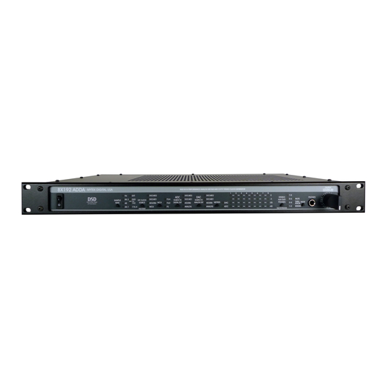
8X192 ADDA 8 CHANNEL MASTERING ANALOG TO DIGITAL AND DIGITAL TO ANALOG CONVERTER USER MANUAL VER.FEB/2006... - Page 2 This manual may be updated Download the newest version at: http://www.mytekdigital.com/manuals/8x192adda_manual.pdf For technical support, technical tips and support check: http://www.mytekdigital.com/products/8x192adda.htm or contact Mytek tech support at: info2006@mytekdigital.com or at: tel. (646)-613 1822 fax.(212)-202 5331 Mytek 151 Lafayette Street 3rd Fl...
- Page 3 No other warranty is expressed or implied. Any faulty unit should be sent, shipping prepaid, to the manufacturer service center. Prior to shipping the client should obtain from Mytek an RMA# for warranty services. Units sent without RMA# will not be accepted.
-
Page 4: Table Of Contents
Introduction.............…………………………….5 Signal Flow.......…………………………………….....6 Block Schematics................……...7 Back Panel Connections, Cable Wiring.........……...8 Front Panel Controls..........……………...………9 Input/output Gain and other internal adjustments..……......10 Setting Clocks and Signal Sources..........…..12 Specifications................…..16... -
Page 5: Introduction
INTRODUCTION Mytek 8X192 ADDA is an 8 channel Analog to Digital and an 8 channel Digital to Analog converter maticoulsly designed to provide the highest quality signal path. No compromises have been made to sound quality, and we feel that this is the best sounding Mytek converter to date. -
Page 6: Signal Flow
SIGNAL FLOW The 8X192 ADDA has two independent signal paths within the unit. They offer independent signal paths but must operate at the same clock source and sampling frequency. It's recommended that as much as possible the unit should be clocked from its internal CX 797 clock generator. -
Page 7: Block Schematics
BLOCK SCHEMATIC BLOW SLOW FUSE (DEFAULT) -15dBFS GAIN FIXED JUMPER DAC 8 HOOD) (UNDER VAR.GAIN (DEFAULT) -15dBFS GAIN FIXED JUMPER DAC 7 HOOD) (UNDER VAR.GAIN VAR.GAIN (DEFAULT) (UNDER -15dBFS HOOD) GAIN FIXED ADC 8 JUMPER DAC 6 JUMPER FIXED GAIN HOOD) -15dBFS (UNDER... -
Page 8: Back Panel Connections, Cable Wiring
BACK PANEL CONNECTIONS BLOW SLOW FUSE... -
Page 9: Front Panel Controls
FRONT PANEL CONTROLS... -
Page 10: Input/Output Gain And Other Internal Adjustments
AND OTHER INTERNAL ADJUSTMENTS Analog input/output alingment The 8X192 ADDA analog input/output sensitivity comes as factory default fixed at -15dBFs corresponding to +4dB (OVU=1.228VRMS measured between hot and cold). This gain is optimal for most situations and unless another level "is necessary for systemic reasons, we recommend leaving the gain at the default setting. - Page 11 INTERNAL ADJUSTMENTS CONTINUED...
-
Page 12: Setting Clocks And Signal Sources
SETTING CLOCKING AND SIGNAL SOURCES NORMAL OPERATION. AD AND DA ON INTERNAL CLOCK. AD FEEDING THE RECORDER, DA MONITORING RECORDER LED ON LED OFF In this mode both the AD and DA run on the internal clock. This mode provides the lowest jitter and most sonically robust performance. - Page 13 NORMAL OPERATION. AD AND DA ON EXTERNAL WORDCLOCK. AD FEEDING THE RECORDER, DA MONITORING RECORDER LED ON LED OFF In this mode both the AD and DA run on an external clock. Holding the "Ext. Clock Source" button selects this mode. Although this mode does not provide the lowest jitter performance it might be desirable for systemic reasons.
- Page 14 NORMAL OPERATION. AD AND DA ON EXTERNAL CLOCK OTHER THAN WCK. AD FEEDING THE RECORDER, DA MONITORING RECORDER LED ON LED OFF In this mode both the AD and DA run on an external clock. Although this mode does not provides the lowest jitter performance it might be desirable for systemic reasons.
- Page 15 FORMAT CONVERSION OPERATION. ADC IS OFF, DIGITAL IN TO DIGITAL OUT, DA MONITORING DIGITAL IN. LED ON LED OFF In this mode the 8X192 unit can be used for format conversion between all installed digital interfaces. Once a digital input is selected for "SOURCE TO DIGITAL", the "SAMPLE RATE" switch is disabled and EXT.CLOCK SOURCE and SOURCE TO ANALOG OUT automatically set to selected digital input.
-
Page 16: Specifications
Specifications ADC* Conversion: Linear, 1 Bit * 128x oversampling at 44.1-48kHz 64x oversampling at 88.2-192kHz, optional 64xDSD and 128xDSD Resolution: 24 bit, ( or 1 bit DSD) Sample rates: 44.1kHz, 48kHz, 88.2kHz, 96kHz, 176.4kHz, 192kHz or wordclock 25-200kHz Dynamic Range: 120dB A-weighted, 117dB Total THD+Noise: -106dB (<0.0005%)
Need help?
Do you have a question about the 8X192 ADDA and is the answer not in the manual?
Questions and answers