
Related Manuals for IBASE Technology MB945


Summary of Contents for IBASE Technology MB945
- Page 1 MB945 Socket LGA775 Intel Q45 Chipset ® Industrial Motherboard USER’S MANUAL Version 1.0B...
- Page 2 Acknowledgments Award is a registered trademark of Award Software International, Inc. PS/2 is a trademark of International Business Machines Corporation. Intel is a registered trademark of Intel Corporation. Microsoft Windows is a registered trademark of Microsoft Corporation. Winbond is a registered trademark of Winbond Electronics Corporation.
-
Page 3: Table Of Contents
............5 Installing the CPU ............... 6 ATX Power Installation ............7 Installing the Memory ............8 Setting the Jumpers ............. 9 Connectors on MB945 ............14 BIOS Setup ............27 Drivers Installation ........50 Intel Chipset Software Installation Utility......51 Intel Graphics Driver Installation ........ - Page 4 NOTE FOR iAMT 1. Assuming the drivers DVD is in D drive, the path for the iAMT files is in D:\Intel\Q45\iAMT\iAMT5.0 2. This note only applies if you are using the MB945AF motherboard. MB945 User’s Manual...
-
Page 5: Introduction
INTRODUCTION Introduction Checklist Your MB945 motherboard package should include the items listed below: • The MB945 motherboard • This User’s manual • 1 Back I/O shield • 1 IDE cable • 1 Floppy cable • 1 SATA cable • 1 Serial-Port cable •... -
Page 6: Product Description
INTRODUCTION Product Description The MB945 LGA 775 motherboard incorporates the Intel Q45 chipset that utilizes a single LGA775 processor and supports 800/1066/1333MT/s (200/266/333 MHz) FSB. The Q45 chipset is designed for use with the Core 2 processor family, including a faster 1333 MHz system bus. The integrated GMCH component provides the CPU interface, DDR3 interface, Hub Interface and PCI Express graphics interface. -
Page 7: Specifications
Chipset GMCH : AC82Q45, 34mm x 34mm, 1254-pin FC-BGA ICH10DO: AF82801JDO, 31mm x 31mm, 676-pin mBGA BIOS Award BIOS, support ACPI Function DDRIII 800/1066MHz Memory - DIMM x 4 (w/o ECC), Max. 8GB Q45 built-in Intel gen.5.0 Graphics Media Accelerator , supports DirectX10 (Vista), Integrated DP, DVI, VGA SDVO;... -
Page 8: Board Dimensions
INTRODUCTION Board Dimensions MB945 User’s Manual... -
Page 9: Installations
INSTALLATIONS Installations This section provides information on how to use the jumpers and connectors on the MB945/MB945F in order to set up a workable system. The topics covered are: Installing the CPU ................. 6 ATX Power Installation ................. 7 Installing the Memory ................8 Setting the Jumpers ................ -
Page 10: Installing The Cpu
INSTALLATIONS Installing the CPU The MB945 motherboard supports an LGA 775 processor socket for Intel Core 2 Duo and Intel Core2 Quad processors. The LGA 775 processor socket comes with a lever to secure the processor. Refer to the pictures below, from left to right, on how to place the processor into the CPU socket. -
Page 11: Atx Power Installation
ATX_12V_2X1 is a 8-pin 12V power connector. The 24-pin power connector can to be connected to a standard 20-pin ATX power connector in a standard ATX power supply (Min. 400watt). Note: The power supply 5VSB voltage must be at least 2A. MB945 User’s Manual... -
Page 12: Installing The Memory
INSTALLATIONS Installing the Memory The MB945 motherboard supports four DDR3 memory sockets for a maximum total memory of 8GB in DDR memory type. It supports DDR3 800/1066. Basically, the system memory interface has the following features: Supports two 64-bit wide DDR data channels Available bandwidth up to 6.4GB/s (DDR3 800) for single-channel... -
Page 13: Setting The Jumpers
INSTALLATIONS Setting the Jumpers Jumpers are used on MB945/MB945F to select various settings and features according to your needs and applications. Contact your supplier if you have doubts about the best configuration for your needs. The following lists the connectors on MB945/MB945F and their respective functions. - Page 14 JP7: ME (Management Engine) – Disabled / pin closed ..... 12 JP8: Clear CMOS Contents ..............12 JP9: Compact Flash Socket Master/Slave Setting ....... 12 JP10: COM2 RS232 +5V/+12V Power Setting ........12 JP11: RS232/422/485 (COM2) Selection ..........13 JP6: Gigabit LAN (Intel 574L) Setting ..........13 MB945 User’s Manual...
-
Page 15: Jp2: Ps/2 Keyboard & Mouse Power Setting
JP4: COM4 RS232 +5V/+12V Power Setting Setting Function Pin 1-2 +12V Short/Closed Pin 3-4 Normal Short/Closed Pin 5-6 Short/Closed JP5: COM3 RS232 +5V/+12V Power Setting Setting Function Pin 1-2 +12V Short/Closed Pin 3-4 Normal Short/Closed Pin 5-6 Short/Closed MB945 User’s Manual... -
Page 16: Jp7: Me (Management Engine) - Disabled / Pin Closed
Normal Short/Closed Pin 2-3 Clear CMOS Short/Closed JP9: Compact Flash Socket Master/Slave Setting Compact Flash Master Slave JP10: COM2 RS232 +5V/+12V Power Setting JP10 Setting Function Pin 1-2 +12V Short/Closed Pin 3-4 Normal Short/Closed Pin 5-6 Short/Closed MB945 User’s Manual... -
Page 17: Jp11: Rs232/422/485 (Com2) Selection
The following table describes the jumper settings for COM2 selection. COM2 RS-232 RS-422 RS-485 Function Short: Short: Short: Jumper 9-11 Setting 10-12 8-10 8-10 (pin closed) 15-17 13-15 13-15 16-18 14-16 14-16 Note: Factory is default RS-232 JP6: Gigabit LAN (Intel 574L) Setting Function Disable Enable MB945 User’s Manual... -
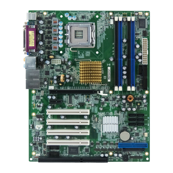
Page 18: Connectors On Mb945
INSTALLATIONS Connectors on MB945 The connectors on MB945 allows you to connect external devices such as keyboard, floppy disk drives, hard disk drives, printers, etc. ATX1: 24-pin ATX Power Connector .............. 16 ATX_12V_2X1: ATX 12V Power Connector ..........16 DDRIII1, DDRIII 3: Channel A DDR3 Socket ..........17 DDRIII2, DDRIII 4: Channel B DDR3 Socket .......... - Page 19 INSTALLATIONS Connectors on MB945/MB945F ATX1: 24-pin ATX Power Connector : SPDIFI/ SPDIFO Connector (Reserved) ATX_12V_2X1: ATX 12V Power Connector J3, J5: ISA Slots DDRIII1, DDRIII 3: Channel A DDR3 Socket J4: SPI Debug To ols Port (Factory use only) DDRIII2, DDRIII 4: Channel B DDR3 Socket...
-
Page 20: Atx1: 24-Pin Atx Power Connector
INSTALLATIONS MB945 Edge Connectors MB945F Edge Connectors ATX1: 24-pin ATX Power Connector Signal Name Pin # Pin # Signal Name 3.3V 3.3V -12V 3.3V Ground Ground PS-ON Ground Ground Ground Ground Ground Power good 5VSB +12V +12V Ground +3.3V ATX_12V_2X1: ATX 12V Power Connector... -
Page 21: Ddriii1, Ddriii 3: Channel A Ddr3 Socket
PD2, parallel data 2 Select PD3, parallel data 3 Ground PD4, parallel data 4 Ground PD5, parallel data 5 Ground PD6, parallel data 6 Ground PD7, parallel data 7 Ground ACK, acknowledge Ground Busy Ground Paper empty Ground Select MB945 User’s Manual... -
Page 22: Cn3: Serial Ports(Com1)
CN5: HD Audio Connector CN8: Gigabit LAN (Intel 567LM) RJ-45&USB 4/5 Connector CN9: Gigabit LAN (Intel 574L) RJ-45 &USB 10/11 Connector CN10: Compact Flash Type II Socket Note: The CompactFlash interface cannot be used simultaneously with the IDE interface. MB945 User’s Manual... -
Page 23: Ide1: Primary Ide Connectors
Note: The CompactFlash interface cannot be used simultaneously with the IDE interface. SATA1~SATA6: SATAII Connectors Pin # Signal Name Ground Ground Ground CD_IN1: CD-In Audio Connector Pin # Signal Name CD Audio R Ground Ground CD Audio L MB945 User’s Manual... -
Page 24: Com3,Com4: Com3, Com4 Serial Ports(Rs232)
J2: SPDIFI/ SPDIFO Connector (Reserved) Pin # Signal Name SPDIF/I Ground SPDIF/O Ground J3, J5: ISA Slots ISA slot does not support ISA master & DMA access function, but only ISA peripheral cards. J4: SPI Debug Tools Port (Factory use only) MB945 User’s Manual... -
Page 25: J6: Com2 Serial Port
RS-232 R2-422 RS-485 DATA- DATA+ Ground Ground Ground RTS- RTS+ CTS+ CTS- J7: System Function Connector J7 provides connectors for system indicators that provide light indication of the computer activities and switches to change the computer status. MB945 User’s Manual... - Page 26 Reset Switch: Pins 9 and 19 The reset switch allows the user to reset the system without turning the main power switch off and then on again. Orientation is not required when making a connection to this header. MB945 User’s Manual...
-
Page 27: J8: Irda Connector
ON/OFF circuitry. Signal Name Pin # Pin # Signal Name Ground Out3 Out1 Out2 Out0 F_AUDIO1: Audio Front Header Signal Name Pin # Pin # Signal Name MIC2_L Ground MIC2_R Presence# Line2_R MIC2_ID Sense Line2_L Line2_ID MB945 User’s Manual... -
Page 28: F_Usb1: Usb8/Usb9 Connector
CPU_FAN1: CPU Fan Power Connector Pin # Signal Name Ground +12V Rotation detection Control SYS_FAN1: system Fan1 Power Connector Pin # Signal Name Ground +12V Rotation detection SYS_FAN3: SYSTEM Fan2 Power Connector Pin # Signal Name Ground +12V Rotation detection MB945 User’s Manual... -
Page 29: Fdd1: Floppy Drive Connector
Write data Ground Write gate Ground Track 00 Ground Write protect FDD1 Ground Read data Ground Side 1 select Ground Diskette change PCIE1: x16 PCI Express Slot PCIE2: x1 PCI Express Slots PCI1, PCI2, PCI3, PCI4: PCI Slots MB945 User’s Manual... - Page 30 INSTALLATIONS This page is intentionally left blank. MB945 User’s Manual...
-
Page 31: Bios Setup
BIOS SETUP BIOS Setup This chapter describes the different settings available in the Award BIOS that comes with the board. The topics covered in this chapter are as follows: BIOS Introduction ..................28 BIOS Setup ....................28 Standard CMOS Setup ................. -
Page 32: Bios Introduction
The Award BIOS provides a Setup utility program for specifying the system configurations and settings. The BIOS ROM of the system stores the Setup utility. When you turn on the computer, the Award BIOS is immediately activated. Pressing the <Del> key immediately allows you to enter the Setup utility. - Page 33 Note: If the system cannot boot after making and saving system changes with Setup, the Award BIOS supports an override to the CMOS settings that resets your system to its default. Warning: It is strongly recommended that you avoid making any changes to the chipset defaults.
-
Page 34: Standard Cmos Setup
The following describes each item of this menu. Date The date format is: Day : Sun to Sat Month : 1 to 12 Date : 1 to 31 Year : 1999 to 2099 MB945 User’s Manual... - Page 35 To set the time, highlight the “Time” field and use the <PgUp>/ <PgDn> or +/- keys to set the current time. IDE Channel Master/Slave MB945 with ICH10DO supports 6 Serial ATA connectors; MB945series boards with JMicron controller support 1 CF and 1 IDE connectors.
- Page 36 The system boot will not be halted for a disk error; it will stop for all other errors. All, But Disk/Key The system boot will not be halted for a key- board or disk error; it will stop for all others. MB945 User’s Manual...
-
Page 37: Advanced Bios Features
Quick Power On Self Test When enabled, this field speeds up the Power On Self Test (POST) after the system is turned on. If it is set to Enabled, BIOS will skip some items. MB945 User’s Manual... - Page 38 BIOS SETUP MB945 User’s Manual...
- Page 39 Settings are from 6 to 30 characters per second. Typematic Delay (Msec) When the typematic rate is enabled, this item allows you to set the time interval for displaying the first and second characters. By default, this item is set to 250msec. MB945 User’s Manual...
- Page 40 The default setting is Disabled. Baud Rate This configuration is supported only with MB945AF (with iAMT function). The default setting is 19200. Agent after boot This configuration is supported only with MB945AF (with iAMT function). The default setting is Enabled. MB945 User’s Manual...
-
Page 41: Advanced Chipset Features
ISA cards. This memory must be mapped into the memory space below 16 MB. The choices are Enabled and Disabled. PCI Express Root Port Func Press Enter to configure this field. Disable MCHBAR MMIO By default, this feature is enabled. MB945 User’s Manual... - Page 42 PEG/On Chip VGA Control: Auto On-Chip Frame Buffer Size: 32MB DVMT Mode: Enabled DVMT/FIXED memory Size: 256MB PAVP Mode: Lite SDVO Device Setting: None SDVO LVDS Protocol: 1 Ch 18bit SDVO Panel Number: 640 x 480 Boot Display: CRT MB945 User’s Manual...
-
Page 43: Integrated Peripherals
Menu Level > RxD , TxD Active Hi, Lo IR Transmission Delay Enabled UR2 Duplex Mode Half Use IR Pins IR-Rx2Tx2 Onboard Parallel Port 378/IRQ7 Parallel Port Mode EPP Mode Select EPP1.7 ECP Mode Use DMA PWRON After PWR-Fail MB945 User’s Manual... -
Page 44: Ide Hdd Block Mode
When Auto is selected, the BIOS will select the best available mode. IDE Primary/Secondary Master/Slave UDMA These fields allow your system to improve disk I/O throughput to 33Mb/sec with the Ultra DMA/33 feature. The options are Auto and Disabled. MB945 User’s Manual... - Page 45 SATA performance with native command queuing & native hot plug. Select [RAID] to use SATA as RAID function. RAID function is supported on the board if it uses ICH10DO. (MB945 supports 6 x SATA with RAID.) LEGACY Mode Support When the Serial ATA (SATA) is set with the legacy mode enabled, then the SATA is set to the conventional IDE mode.
- Page 46 Enabled. In order to use USB 2.0, necessary OS drivers must be installed first. Please update your system to Windows 2000 SP4 or Windows XP SP2. USB Keyboard/Mouse/Storage Function The options for this field are Enabled and Disabled. By default, this field is set to Enabled. MB945 User’s Manual...
-
Page 47: Power Management Setup
ACPI Function Enable this function to support ACPI (Advance Configuration and Power Interface). ACPI Suspend The default setting of the ACPI Suspend mode is S1(POS). RUN VGABIOS if S3 Resume The default setting of this field is Auto. MB945 User’s Manual... - Page 48 In the Delay 4 Sec mode, the system powers off when the power button is pressed for more than four seconds or enters the suspend mode when pressed for less than 4 seconds. MB945 User’s Manual...
- Page 49 CPU's RDTSC instruction. HPET is not supported in Windows XP, Windows Server 2003, or earlier Windows versions. HPET is supported under Linux and Windows Vista. By default, this field is enabled. HPET Mode By default, this field is set to 32-bit mode. MB945 User’s Manual...
-
Page 50: Init Display First
MPEG ISA/VESA VGA card. When this field is disabled, a PCI/VGA cannot work with an MPEG ISA/VESA card. Maximum Payload Size The default setting of the PCI Express Maximum Payload Size is 128. MB945 User’s Manual... -
Page 51: Pc Health Status
This function can help prevent damage to the system that is caused by overheating. Temperatures/Fan Speeds/Voltages These fields are the parameters of the hardware monitoring function feature of the board. The values are read-only values as monitored by the system and show the PC health status. MB945 User’s Manual... -
Page 52: Auto Detect Pci Clk
This field enables or disables the auto detection of the PCI clock. Spread Spectrum This field sets the value of the spread spectrum. The default setting is Disabled. This field is for CE testing use only CPU Host/SRC/PCI Clock This field is set as Default. MB945 User’s Manual... -
Page 53: Load Fail-Safe Defaults
Select this option to exit the Setup utility without saving the changes you have made in this session. Typing “Y” will quit the Setup utility without saving the modifications. Typing “N” will return you to Setup utility. MB945 User’s Manual... -
Page 54: Drivers Installation
Intel Management Engine Interface ............. 61 Intel Active Management Technology ..........63 IMPORTANT NOTE: After installing your Windows operating system (Windows 2000/XP/Vista), you must install first the Intel Chipset Software Installation Utility before proceeding with the drivers installation. MB945 User’s Manual... -
Page 55: Intel Chipset Software Installation Utility
Windows 2000/XP/Vista. (Before installing this utility, please update your system to Windows 2000 SP4 or Windows XP SP2) 1. Insert the drivers DVD into the DVD drive. Click Intel and then Intel(R) Q45 Chipset Drivers. Click Intel(R) Chipset Software Installation Utility. MB945 User’s Manual... - Page 56 3. On the Readme Information screen, click Next to continue. When the Setup Progress screen appears, click Next to continue. 4. Setup process is now complete. Click Finish to restart the computer. MB945 User’s Manual...
-
Page 57: Intel Graphics Driver Installation
Intel(R) Q45 Chipset Drivers. Click Intel(R) Q45 Chipset Family Graphics Driver. 2. When the Welcome screen appears, click Next to continue. Click Yes to accept the software license agreement and proceed with the installation process. 3. On the Readme Information screen, click Next to continue. MB945 User’s Manual... - Page 58 DRIVERS INSTALLATION 4. When the Setup Progress screen appears, click Next to continue. 5. Setup is complete. Click Finish to restart the computer. MB945 User’s Manual...
-
Page 59: Realtek Hd Codec Audio Driver Installation
Follow the steps below to install the Realtek High Definition Codec Audio Driver. 1. Insert the drivers DVD into the DVD drive. Click Intel and then Intel(R) Q45 Chipset Drivers. Click Realtek High Definition Codec Audio Driver. MB945 User’s Manual... - Page 60 DRIVERS INSTALLATION 2. When the Welcome screen appears, click Next to continue. 3. InstallShield Wizard is complete. Click Finish to restart the computer. MB945 User’s Manual...
-
Page 61: Lan Drivers Installation
1. Insert the drivers DVD into the DVD drive. Click Intel and then Intel(R) Q45 Chipset Drivers. Click Intel(R) PRO LAN Network Drivers. 2. When the Welcome screen appears, click Next to continue. Click Yes to accept the software license agreement and proceed with the process. MB945 User’s Manual... - Page 62 3. On the Setup Options screen, the checkbox for Drivers should be checked. Now, click Next to continue. 4. The wizard is ready to begin installation Now, click Install to continue. 5. InstallShield wizard is complete. Click Finish. MB945 User’s Manual...
-
Page 63: Intel Matrix Storage Manager Driver
1. Insert the drivers DVD in the DVD drive. Click Intel and then Intel(R) Q45 Chipset Drivers. Click Intel(R) Matrix Storage Manager Drivers. 2. In the welcome screen to the Setup Program, click Next. In the next “warning” page as below, click Next. MB945 User’s Manual... - Page 64 3. In the License Agreement page, click Yes to agreement with the agreement. Then , in the Readme File Information page, click Next. 4. In the Setup Progress page, click Next, and restart the computer when prompted. MB945 User’s Manual...
-
Page 65: Intel Management Engine Interface
2. In the next page, click Intel(R) MEI Driver. 3. In the welcome screen to the Setup Program, click Next. In the next License Agreement page, click Yes to accept to all the terms with the agreement and continue the setup program. MB945 User’s Manual... - Page 66 DRIVERS INSTALLATION 4. Click Yes in the Readme File Information page and continue the setup program. Setup is now in progress. Click Next. 5. Setup is complete. Click Finish. MB945 User’s Manual...
-
Page 67: Intel Active Management Technology
4. The next screen is for the Software Update Installation Wizard. It will install the update for “Hotfix for Windows XP (KB942288-v3). Click Next to continue. 5. In the License Agreement screen, click Next to agree with the Microsoft Software License Terms. 6. Setup is complete. Click Finish. MB945 User’s Manual... - Page 68 Microsoft .NET Frame 3.5 SP1 Setup. Follow the instructions accordingly to finish the setup process. In this screen, check the checkbox for “I have read and ACCEPT the terms of the License Agreement”, and then click Install. MB945 User’s Manual...
- Page 69 DRIVERS INSTALLATION 8. After Setup is complete, click Exit. MB945 User’s Manual...
- Page 70 9. Once the Microsoft .NET Frame 3.5 SP1 Setup is complete, the next screen shows the Intel Active Management Technology Setup Progress. Click Next to continue. 10. The Intel Active Management Technology Setup is now complete. Click Finish to complete the setup process. MB945 User’s Manual...
- Page 71 DRIVERS INSTALLATION This page is intentionally left blank. MB945 User’s Manual...
-
Page 72: Appendix
Parallel Port #1(LPT1) 360h - 36Fh Network Ports 3B0h - 3BFh Monochrome & Printer adapter 3C0h - 3CFh EGA adapter 3D0h - 3DFh CGA adapter 3F0h - 3F7h Floppy Disk Controller 3F8h - 3FFh Serial Port #1(COM1) MB945 User’s Manual... -
Page 73: Interrupt Request Lines (Irq)
Serial Port #2 IRQ4 Serial Port #1 IRQ5 Reserved IRQ6 Floppy Disk Controller IRQ7 Parallel Port #1 IRQ8 Real Time Clock IRQ9 Reserved IRQ10 Reserved IRQ11 Reserved IRQ12 PS/2 Mouse IRQ13 80287 IRQ14 Primary IDE IRQ15 Secondary IDE MB945 User’s Manual... -
Page 74: Watchdog Timer Configuration
Winbond 83627DHG, program abort.\n"); return(1); WDTInitial(); WDTEnable(10); WDTDisable(); return 0; //--------------------------------------------------------------------------- void WDTInitial(void) unsigned char bBuf; bBuf = Get_W627DHG_Reg(0x2D); bBuf &= (~0x01); Set_W627DHG_Reg(0x2D, bBuf); //Enable WDTO //--------------------------------------------------------------------------- void WDTEnable(unsigned char NewInterval) unsigned char bBuf; MB945 User’s Manual... - Page 75 // IMPLIED WARRANTIES OF MERCHANTABILITY AND/OR FITNESS FOR A PARTICULAR // PURPOSE. //--------------------------------------------------------------------------- #include "W627DHG.H" #include <dos.h> //--------------------------------------------------------------------------- unsigned int W627DHG_BASE; void Unlock_W627DHG (void); void Lock_W627DHG (void); //--------------------------------------------------------------------------- unsigned int Init_W627DHG(void) unsigned int result; unsigned char ucDid; W627DHG_BASE = 0x4E; result = W627DHG_BASE; MB945 User’s Manual...
- Page 76 LD); Lock_W627DHG(); //--------------------------------------------------------------------------- void Set_W627DHG_Reg( unsigned char REG, unsigned char DATA) Unlock_W627DHG(); outportb(W627DHG_INDEX_PORT, REG); outportb(W627DHG_DATA_PORT, DATA); Lock_W627DHG(); //--------------------------------------------------------------------------- unsigned char Get_W627DHG_Reg(unsigned char REG) unsigned char Result; Unlock_W627DHG(); outportb(W627DHG_INDEX_PORT, REG); Result = inportb(W627DHG_DATA_PORT); Lock_W627DHG(); return Result; //--------------------------------------------------------------------------- MB945 User’s Manual...
- Page 77 APPENDIX This page is intentionally left blank. MB945 User’s Manual...
Need help?
Do you have a question about the MB945 and is the answer not in the manual?
Questions and answers