
Related Manuals for IBASE Technology MB995


Summary of Contents for IBASE Technology MB995
- Page 1 MB995 Core™ i7/i5/i3 ® Gen. Intel ® / Xeon ATX Motherboard User’s Manual Version 1.0 (July 2018)
- Page 2 No part of this publication may be reproduced, copied, stored in a retrieval system, translated into any language or transmitted in any form or by any means, electronic, mechanical, photocopying, or otherwise, without the prior written consent of IBASE Technology, Inc. (hereinafter referred to as “IBASE”). Disclaimer IBASE reserves the right to make changes and improvements to the products described in this document without prior notice.
-
Page 3: Compliance
0.1% by weight (1000 ppm) except for cadmium, limited to 0.01% by weight (100 ppm). • Lead (Pb) • Mercury (Hg) • Cadmium (Cd) • Hexavalent chromium (Cr6+) • Polybrominated biphenyls (PBB) • Polybrominated diphenyl ether (PBDE) MB995 User’s Manual... -
Page 4: Important Safety Information
CAUTION Replace only with the same or equivalent type recommended by the manufacturer. Dispose of used batteries according to the manufacturer’s instructions or recycle them at a local recycling facility or battery collection point. MB995 User’s Manual... -
Page 5: Warranty Policy
Software in use (such as OS and application software, including the version numbers) If repair service is required, you can download the RMA form at http://www.ibase.com.tw/english/Supports/RMAService/. Fill out the form and contact your distributor or sales representative. MB995 User’s Manual... -
Page 6: Table Of Contents
2.1.1 Installing the Memory ............12 Setting the Jumpers ................13 2.2.1 How to Set Jumpers ............. 13 Jumper & Connector Locations on MB995 ......... 14 Jumpers Quick Reference ..............15 2.4.1 Clearing CMOS Data (JP6) ..........15 2.4.2 PCIe (x16) Bifurcation Selection (JP2 & JP3) ...... 16 Connectors Quick Reference ............. - Page 7 Network Stack Configuration ..........53 4.4.13 CSM Configuration ...............53 4.4.14 NVMe Configuration .............53 Chipset Settings .................54 4.5.1 System Agent (SA) Configuration .........54 4.5.2 PCH-IO Configuration ............56 Security Settings ................57 Boot Settings ..................58 Save & Exit Settings ................59 Appendix ..................61 MB995 User’s Manual...
- Page 8 I/O Port Address Map ................ 62 Interrupt Request Lines (IRQ) ............65 Watchdog Timer Configuration ............67 On-Board Connector Types ............... 71 MB995 User’s Manual viii...
-
Page 9: Chapter 1 General Information
Chapter 1 General Information The information provided in this chapter includes: • Features • Packing List • Specifications • Block Diagram • Board Overview • Board Dimensions... -
Page 10: Introduction
Introduction ® MB995 is an ATX motherboard based on the Intel Gen. Processor that features four DDR memory sockets and supports up to 64 GB and high- performance graphics processing to create media-rich content and brilliant HD entertainment with DVI-D, HDMI (2.0a) and DisplayPort display interface. -
Page 11: Packing List
General Information Packing List Your MB995 package should include the items listed below. If any of the items below is missing, contact the distributor or dealer from whom you purchased the product. • MB995 Motherboard • I/O shield • SATA cable (SATA-3F) •... -
Page 12: Specifications
+3.3V: 0.67A H/W Monitor Watchdog Yes (256 segments, 0, 1, 2…255 sec / min) Timer BIOS AMI BIOS RAID RAID 0/1/5/10 iSmart iAMT 11.6 ® ® vPro Yes, supported by Intel Xeon E / Core™ i7/i5 processors. MB995 User’s Manual... - Page 13 Operating: 0 ~ 60 °C (32 ~ 140 °F) • Temperature Storage: -20 ~ 80 °C (-4 ~ 176 °F) • Relative 0 ~ 90 %, non-condensing at 60 °C Humidity All specifications are subject to change without prior notice. MB995 User’s Manual...
-
Page 14: Block Diagram
Block Diagram MB995 User’s Manual... -
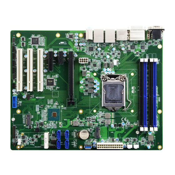
Page 15: Overview
General Information Overview Top View I/O View Name Name COM1 Port Audio Line-In COM2 Port Audio Line-Out DVI-D Port Microphone-In 7 USB 3.1 Ports DisplayPort GbE LAN Ports HDMI Port MB995 User’s Manual... - Page 16 Bottom View *The photos above are for reference only. Some minor components may differ. MB995 User’s Manual...
-
Page 17: Dimensions
General Information Dimensions MB995 User’s Manual... - Page 18 This page is intentionally left blank. MB995 User’s Manual...
-
Page 19: Chapter 2 Hardware Configuration
Chapter 2 Hardware Configuration This section provides information on jumper settings and connectors on the board in order to set up a workable system. The topics covered are: • Essential installations before you begin: CPU and the memory • Jumper and connector locations •... -
Page 20: Installations
Gently push the module in an upright position until the ejector tabs of the memory slot close to hold the module in place when the module touches the bottom of the slot. To remove the module, press the ejector tabs outwards with your fintertips to eject the module. MB995 User’s Manual... -
Page 21: Setting The Jumpers
1 2 3 When two pins of a jumper are encased in a jumper cap, this jumper is closed, i.e. turned On. When a jumper cap is removed from two jumper pins, this jumper is open, i.e. turned Off. MB995 User’s Manual... -
Page 22: Jumper & Connector Locations On Mb995
Jumper & Connector Locations on MB995 MB995 User’s Manual... -
Page 23: Jumpers Quick Reference
Hardware Configuration Jumpers Quick Reference Function Jumper Name Page Clearing CMOS Data PCIe (x16) Bifurcation Selection JP2, JP3 Factory Use Only JP4, JP5 2.4.1 Clearing CMOS Data (JP6) Function Pin closed Illustration Normal (default) Clear CMOS MB995 User’s Manual... -
Page 24: Pcie (X16) Bifurcation Selection (Jp2 & Jp3)
Pin closed Illustration JP2: Open 1 x PCIe (x16) (default) JP3: Open JP2: Open 2 x PCIe (x8) JP3: Close JP2: Close RSVD JP3: Open JP2: Close 1 x PCIe (x8) 2 x PCIe (x4) JP3: Close MB995 User’s Manual... -
Page 25: Connectors Quick Reference
CN9, CN10, CN11*, SATA III Port CN12, CN13, CN14* DDR4 UDIMM Slot J11, J12, J13, J14 M.2 Slot J17 (E2230), J19 (M2280) Mini-PCIe Slot for mSATA Factory Use Only J9, J24 CN11 and CN14 are available for MB995VF-C246 only. MB995 User’s Manual... -
Page 26: Com1 & Com2 Rs-232/422/485 Ports (Cn3)
DCD, Data carrier detect DSR, Data set ready RXD, Receive data RTS, Request to send TXD, Transmit data CTS, Clear to send DTR, Data terminal RI, Ring indicator ready Ground Signal Name RS-232 RS-422 RS-485 DATA- DATA+ Ground Ground Ground MB995 User’s Manual... -
Page 27: Front Panel Audio Connector (J1)
Hardware Configuration 2.5.2 Front Panel Audio Connector (J1) Signal Name Signal Name MIC IN_L Ground MIC IN_R LINE_R Ground Sense LINE_L Ground MB995 User’s Manual... -
Page 28: Digital I/O Connector (J2)
2.5.3 Digital I/O Connector (J2) (4-In, 4-Out) Signal Name Signal Name Ground OUT3 OUT1 OUT2 OUT0 MB995 User’s Manual... -
Page 29: Com3, Com4, Com5, Com6 Rs-232 Ports (J8, J7, J5, J3)
J5: COM5 J3: COM6 Signal Name Signal Name DCD, Data carrier detect RXD, Receive data DTR, Data terminal TXD, Transmit data ready Ground DSR, Data set ready RTS, Request to send CTS, Clear to send RI, Ring indicator MB995 User’s Manual... -
Page 30: Ps/2 Keyboard & Mouse Ports (J10)
2.5.5 PS/2 Keyboard & Mouse Ports (J10) Signal Name Signal Name KBDA KBCL Ground Ground 2.5.6 USB 2.0 Ports (J15) Signal Name Signal Name Ground Ground MB995 User’s Manual... -
Page 31: Usb 3.1 Ports (J16)
Hardware Configuration 2.5.7 USB 3.1 Ports (J16) Signal Name Signal Name P2_U2_D+ P1_SSRX- P2_U2_D- P1_SSRX+ Ground Ground P2_SSTX+ P1_SSTX- P2_SSTX- P1_SSTX+ Ground Ground P2_SSRX+ P1_U2_D- P2_SSRX- P1_U2_D+ MB995 User’s Manual... -
Page 32: Front Panel Settings Connector (J18)
• Hard Disk Drive LED Connector (Pins 19 and 20) This connector connects to the hard drive activity LED on control panel. This LED will flash when the HDD is being accessed. MB995 User’s Manual... -
Page 33: S3 Status Connector (J22)
This LED will light when the system turns on. • Speaker Connector (Pins 2 and 8) Connect the two pins for setting up the system output speaker. 2.5.9 S3 Status Connector (J22) Signal Name Signal Name 3VDUAL Ground VCC3 Ground MB995 User’s Manual... -
Page 34: Atx Power Connector (J23)
2.5.10 ATX Power Connector (J23) Signal Name Signal Name 3.3V 3.3V 3.3V -12V Ground Ground PS-ON Ground Ground Ground Ground Ground Power good 5VSB +12V +12V 3.3V Ground MB995 User’s Manual... -
Page 35: Atx 12V Power Connector (Atx_12V_2X1)
Hardware Configuration 2.5.11 ATX 12V Power Connector (ATX_12V_2X1) Signal Name Signal Name Ground +12V Ground +12V Ground +12V Ground +12V MB995 User’s Manual... -
Page 36: Cpu Fan Power Connector (Cpu_Fan1)
2.5.12 CPU Fan Power Connector (CPU_FAN1) Signal Name Signal Name Ground Rotation detection +12V Control MB995 User’s Manual... -
Page 37: System Fan Power Connector (Sys_Fan1, Sys_Fan2)
Hardware Configuration 2.5.13 System Fan Power Connector (SYS_FAN1, SYS_FAN2) SYS_FAN2 SYS_FAN1 Signal Name Signal Name Ground Rotation detection +12V Control MB995 User’s Manual... - Page 38 This page is intentionally left blank. MB995 User’s Manual...
-
Page 39: Chapter 3 Drivers Installation
Chapter 3 Drivers Installation This chapter introduces installation of the following drivers: • ® Intel Chipset Software Installation Utility • HD Graphics Driver • HD Audio Driver • LAN Driver • ® Intel Management Engine Drivers Installation... -
Page 40: Introduction
Follow the instructions below to complete the installation. Insert the disk enclosed in the package with the board. Click Intel on the left pane and then Intel(R) Coffeelake Chipset Drivers on the right pane. Click Intel(R) Chipset Software Installation Utility. MB995 User’s Manual... -
Page 41: Hd Graphics Driver Installation
The driver has been completely installed. Restart the computer for changes to take effect. HD Graphics Driver Installation Click Intel on the left pane and then Intel(R) Coffeelake Chipset Drivers on the right pane. Click Intel(R) HD Graphics Driver. MB995 User’s Manual... - Page 42 When the Welcome screen appears, click Next to continue. Accept the license agreement and click Next. On the Readme File Information screen, click Next until the installation starts. The driver has been completely installed. Restart the computer for changes to take effect. MB995 User’s Manual...
-
Page 43: Hd Audio Driver Installation
Drivers on the right pane. Click Realtek High Definition Audio Driver. On the Welcome screen of the InstallShield Wizard, click Next. Click Next until the installation starts. The driver has been completely installed. Restart the computer for changes to take effect. MB995 User’s Manual... -
Page 44: Lan Driver Installation
LAN Driver Installation Click Intel on the left pane and then Intel(R) Coffeelake Chipset Drivers on the right pane. Click Intel(R) PRO LAN Network Drivers.. When the Welcome screen appears, click Next. MB995 User’s Manual... -
Page 45: Intel ® Management Engine Drivers Installation
The wizard is ready for installation. Click Install. As the installation is complete, restart the computer for changes to take effect. ® Intel Management Engine Drivers Installation Click Intel on the left pane and then Intel(R) Coffeelake Chipset Drivers on the right pane. MB995 User’s Manual... - Page 46 When the Welcome screen appears, click Next. Accept the license agreement, choose a destination folder and click Next until the installation starts. As the driver has been sccessfully installed, restart the computer for changes to take effect. MB995 User’s Manual...
-
Page 47: Chapter 4 Bios Setup
Chapter 4 BIOS Setup This chapter describes the different settings available in the AMI BIOS that comes with the board. The topics covered in this chapter are as follows: • Main Settings • Advanced Settings • Chipset Settings • Boot Settings •... -
Page 48: Introduction
These defaults have been carefully chosen by both AMI and your system manufacturer to provide the absolute maximum performance and reliability. Changing the defaults could make the system unstable and crash in some cases. MB995 User’s Manual... -
Page 49: 4.3 Main Settings
Description System Date Sets the date. Use theTab to switch between the data elements. Default Ranges: Year: 2005-2099 Months: 1-12 Days: dependent on month System Time Set the time. Use Tab to switch between the Time elements. MB995 User’s Manual... -
Page 50: 4.4 Advanced Settings
User Select Monitor Output by Graphic Output Protocol Policy Protocol USB Configuration Displays USB configuration parameters. Network Stack Network Stack Settings Configuration Enables / Disables option ROM execution CSM Configuration settings, etc. NVMe Configuration NVMe Device Options Settings MB995 User’s Manual... -
Page 51: Connectivity Configuration
Intel components. WWAN Enable Enables/Disables M.w WWAN module. WWAN can only be enabled for re-work board. Discrete Bluetooth SerialIo UART0 needs to be enabled to select Module BT module. Advanced Settings Configure ACPI objects for wireless devices MB995 User’s Manual... -
Page 52: Cpu Configuration
When enabled, a VMM can utilize the Virtualization additional hardware capabilities provided by Technology Vanderpool Technology. Active Processor Number of cores to enable in each processor Cores package. Options: All, 1, 2, 3 Enables / Disables AES (Advanced Encryption Standard). MB995 User’s Manual... -
Page 53: Power & Performance
BIOS Setting Description CPU – Power CPU – Power Management Control Options Management Control Intel SpeedStep Allows more than two frequency ranges to be supported Intel Speed Shift This can be Enabled or Disabled. Technology 4.4.4 PCH-FW Configuration MB995 User’s Manual... -
Page 54: Trusted Computing
TPM 1.2 will restrict support to TPM 1.2 devices. TPM 2.0 will restrict to support TPM 2.0 devices. Auto will support both, with the default set to TPM 2.0 devices. If not found, TPM 1.2 devices will be enumerated. MB995 User’s Manual... -
Page 55: Acpi Settings
(OS/S4 Sleep State). This option may be not effective with some OS. ACPI Sleep State Selects an ACPI sleep state where the system will enter when the Suspend button is pressed. Options: Suspend Disabled, S3 (Suspend to RAM) MB995 User’s Manual... -
Page 56: Ismart Controller
For example, if setting up a schedule from Wednesday 5 p.m. to Thursday 2 a.m., configure two schedule slots. But if setting up a schedule from 3 p.m to 5 p.m. on Wednesday, configure only a schedule slot. MB995 User’s Manual... -
Page 57: F81966 Super Io Configuration
BIOS Setup 4.4.8 F81966 Super IO Configuration BIOS Setting Description Serial Port Sets parameters of Serial Ports. Configuration Enables / Disables the serial port and select an optimal setting for the Super IO device. MB995 User’s Manual... -
Page 58: Hardware Monitor
Options: Disabled / 70 °C / 75 °C / 80 °C / 85 °C / Temperature 90 °C / 95 °C 4.4.10 AMI Graphic Output Protocol Policy BIOS Setting Description Output Select Selects the display output interface MB995 User’s Manual... -
Page 59: Usb Configuration
Options: 1 sec / 5 sec / 10 sec / 20 sec Device reset time-out Seconds of delaying execution of start unit command to USB mass storage device. Options: 10 sec / 20 sec / 30 sec / 40 sec MB995 User’s Manual... - Page 60 Options: Auto / Manual Mass storage device emulation type. ‘Auto’ Mass Storage Devices enumerates devices according to their media format. Optical deives are emulated as ‘CDROM’. Drives with no media will be emulated according to a drive type. MB995 User’s Manual...
-
Page 61: Network Stack Configuration
Description CSM Support Enables / Disables CSM support. Network Controls the execution of UEFI and Legacy PXE OpROM. Options: Do not launch / Legacy 4.4.14 NVMe Configuration BIOS Setting Description NVMe Configuration NVMe controller and drive information. MB995 User’s Manual... -
Page 62: 4.5 Chipset Settings
BIOS Setting Description System Agent (SA) System Agent (SA) parameters Configuration PCH-IO PCH parameters Configuration 4.5.1 System Agent (SA) Configuration BIOS Setting Description Graphics Configures the graphics settings. Configuration VT-d Checks if VT-d function on MCH is supported. MB995 User’s Manual... - Page 63 16M / 20M / 24M / 28M / 32M/F7 / 36M / 40M / 44M / 48M / 52M / 56M / 60M DVMT Total Gfx Selects DVMT 5.0 total graphic memory size used by the internal graphcis device. Options: 256M / 128M / MAX MB995 User’s Manual...
-
Page 64: Pch-Io Configuration
4.5.2 PCH-IO Configuration BIOS Setting Description SATA and RST Configures SATA devices. Configuration PCH LAN Controller Enables / Disables the onboard NIC. Enables / Disables the integrated LAN to wake Wake on LAN Enable up the system. MB995 User’s Manual... -
Page 65: 4.6 Security Settings
System is in User mode. The mode change requires platform reset. Secure Boot Mode Secure Boot mode options: Standard or Custom. In Custom mode, Secure Boot Policy variables can be configured by a physically present user without full authenticatoin. MB995 User’s Manual... -
Page 66: 4.7 Boot Settings
65535(0xFFFF) means indefinite waiting. Bootup NumLock Selects the keyboard NumLock state. State Quiet Boot Enables / Disables Quiet Boot option. Boot mode select Selects a Boot mode, Legacy / UEFI. Boot Option Priorities Sets the system boot order. MB995 User’s Manual... -
Page 67: 4.8 Save & Exit Settings
Restore Defaults Restores / Loads defaults values for all the setup options. Save as User Saves the changes done so far as User Defaults Defaults. Restore User Restores the user defaults to all the setup Defaults options. MB995 User’s Manual... - Page 68 This page is intentionally left blank. MB995 User’s Manual...
-
Page 69: Appendix
Appendix This section provides the mapping addresses of peripheral devices, the sample code of watchdog timer configuration, and types of on-board connectors. -
Page 70: I/O Port Address Map
Motherboard resources 0x0000164E-0x0000164F Motherboard resources 0x00000020-0x00000021 Programmable interrupt controller 0x00000024-0x00000025 Programmable interrupt controller 0x00000028-0x00000029 Programmable interrupt controller 0x0000002C-0x0000002D Programmable interrupt controller 0x00000030-0x00000031 Programmable interrupt controller 0x00000034-0x00000035 Programmable interrupt controller 0x00000038-0x00000039 Programmable interrupt controller 0x0000003C-0x0000003D Programmable interrupt controller MB995 User’s Manual... - Page 71 Standard SATA AHCI Controller 0x00004080-0x00004083 Standard SATA AHCI Controller 0x00004060-0x0000407F Standard SATA AHCI Controller 0x0000FFF8-0x0000FFFF Intel(R) Active Management Technology - SOL (COM7) 0x00003000-0x00003FFF Intel(R) PCI Express Root Port #10 - A331 0x00002000-0x000020FE Motherboard resources 0x00004000-0x0000403F Intel(R) UHD Graphics 630 MB995 User’s Manual...
- Page 72 Address Device Description 0x00000040-0x00000043 System timer 0x00000050-0x00000053 System timer 0x00000060-0x00000060 Standard PS/2 Keyboard 0x00000064-0x00000064 Standard PS/2 Keyboard 0x0000EFA0-0x0000EFBF Intel(R) SMBus - A323 MB995 User’s Manual...
-
Page 73: Interrupt Request Lines (Irq)
Intel(R) I211 Gigabit Network Connection IRQ 4294967284 Intel(R) I211 Gigabit Network Connection IRQ 4294967283 Intel(R) I211 Gigabit Network Connection IRQ 4294967282 Intel(R) I211 Gigabit Network Connection IRQ 4294967281 Intel(R) I211 Gigabit Network Connection IRQ 4294967280 Intel(R) I211 Gigabit Network Connection MB995 User’s Manual... - Page 74 Standard PS/2 Keyboard IRQ 4294967290 Intel(R) Ethernet Connection (7) I219-LM IRQ 12 Microsoft PS/2 Mouse IRQ 14 Intel(R) Serial IO GPIO Host Controller - 3450 IRQ 16 High Definition Audio Controller IRQ 4294967294 Intel(R) PCIe Controller (x16) - 1901 MB995 User’s Manual...
-
Page 75: Watchdog Timer Configuration
**endptr; char SIO; printf("Fintek 81966 watch dog program\n"); SIO = Init_F81966(); if (SIO == 0) printf("Can not detect Fintek 81966, program abort.\n"); return(1); }//if (SIO == 0) if (argc != 2) printf(" Parameter incorrect!!\n"); return (1); MB995 User’s Manual... - Page 76 = Get_F81966_Reg(0xFA); bBuf &= ~0x01; Set_F81966_Reg(0xFA, bBuf); //disable WDTO output bBuf = Get_F81966_Reg(0xF5); bBuf &= ~0x20; bBuf |= 0x40; Set_F81966_Reg(0xF5, bBuf); //disable WDT //--------------------------------------------------------------------------- //--------------------------------------------------------------------------- // THIS CODE AND INFORMATION IS PROVIDED "AS IS" WITHOUT WARRANTY OF ANY MB995 User’s Manual...
- Page 77 Init_Finish; F81966_BASE = 0x00; result = F81966_BASE; Init_Finish: return (result); //--------------------------------------------------------------------------- void Unlock_F81966 (void) outportb(F81966_INDEX_PORT, F81966_UNLOCK); outportb(F81966_INDEX_PORT, F81966_UNLOCK); //--------------------------------------------------------------------------- void Lock_F81966 (void) outportb(F81966_INDEX_PORT, F81966_LOCK); //--------------------------------------------------------------------------- void Set_F81966_LD( unsigned char LD) Unlock_F81966(); outportb(F81966_INDEX_PORT, F81966_REG_LD); outportb(F81966_DATA_PORT, LD); Lock_F81966(); //--------------------------------------------------------------------------- MB995 User’s Manual...
- Page 78 #define F81966_DATA_PORT (F81966_BASE+1) //--------------------------------------------------------------------------- #define F81966_REG_LD 0x07 //--------------------------------------------------------------------------- #define F81966_UNLOCK 0x87 #define F81966_LOCK 0xAA //--------------------------------------------------------------------------- unsigned int Init_F81966(void); void Set_F81966_LD( unsigned char); void Set_F81966_Reg( unsigned char, unsigned char); unsigned char Get_F81966_Reg( unsigned char); //--------------------------------------------------------------------------- #endif // F81966_H MB995 User’s Manual...
-
Page 79: On-Board Connector Types
ATX Power HAOGUO Connector 01-0018-03 4.2 mm 2*12-pin ATX 12V HAOGUO Power ATX_12V_2X1 01-0018-02 4.2 mm 2*4-pin Connector Techbest CPU Fan Molex Power CPU_FAN1 03I104132S1WT(A)- 47054-1000 Connector [TECHBEST System Fan SYS_FAN1, Molex Power SYS_FAN2 03I104132S1WT(A)- 47054-1000 Connector MB995 User’s Manual...
Need help?
Do you have a question about the MB995 and is the answer not in the manual?
Questions and answers