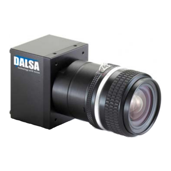
Summarization of Contents
Spyder3 GigE Vision Camera Overview
1.1 Camera Highlights
Key features and programmability of the camera, including responsivity and resolution.
1.2 Camera Performance Specifications
Detailed technical specifications for camera performance, including resolution, pixel size, and rates.
1.3 Image Sensor Description
Information about the dual line scan sensor technology and pixel readout modes.
1.4 Responsivity Characteristics
Graphs showing spectral responsivity for different sensitivity modes and models.
1.5 Supported Industry Standards
Compliance with GigE Vision 1.0 and GenICam specifications.
Mechanicals and Optics
2.1 Mechanical Interface Dimensions
Physical dimensions and mounting details of the camera, including connector locations.
2.2 Mounting Recommendations
Guidance on how to properly mount the camera to ensure proper heat dissipation.
2.3 Optical Interface Information
Details on illumination factors and light sources for image capture.
2.4 Electrical Interface Standards
Information on EMC compliance and electrical interface requirements.
Setting Up the Camera
3.1 Installation Overview
Step-by-step guide for camera installation and software setup.
3.2 Equipment Recommendations
PC, network adapter, and switch requirements for optimal performance.
3.3 Driver Installation Guide
Information on installing and selecting camera drivers for optimal operation.
3.4 Ethernet Connector
Description of the RJ-45 Ethernet connector and its status LEDs.
3.5 Power Connector Details
Details of the 6-pin Hirose power connector and essential power supply guidelines.
3.6 GPIO Connector Pinout
Pinout and signal descriptions for the 15-pin GPIO connector.
3.7 Camera Status LED
Explanation of the camera's diagnostic LED states and their meanings.
EMC Declaration
4.1 Compliance Standards and Requirements
Details on CE, FCC, and Industry Canada EMC compliance standards met by the camera.
Controlling the Camera
5.1 GenICam Interface Explanation
How the camera implements the GenICam specification for device capabilities.
5.2 GenICam Command Reference
List and description of available GenICam commands for camera control.
5.3 Initial Camera Settings
Factory settings applied when the camera is first powered on.
5.4 Output Format Configuration
Settings for sensitivity mode and CCD shift direction.
5.5 Timing: Exposure and Synchronization
Controlling exposure initiation and synchronization signals for image capture.
5.6 Configuring the GPIO Connector
Setting up digital input and output signals via the GPIO connector.
Exposure Control and Timing
6.1 Exposure, Readout, and Line Rate Overview
Introduction to camera operating modes and timing parameters.
6.2 Setting the Exposure Mode
Configuring the camera's exposure synchronization and line rate generation.
6.3 Detailed Exposure Mode Descriptions
Explanation of different exposure modes and their timing diagrams.
Readout Mode Configuration
7.1 Setting the Readout Mode
Clearing dark current charge from sensor gates before readout.
7.2 Immediate Readout Mode (Default)
Image readout including accumulated dark current.
7.3 Gate Dark Current Clear Mode
Continuous clearing of gate dark current for improved image quality.
7.4 Auto Mode for Readout
Automatic switching between dark current clear modes based on line rate.
Data Processing and Calibration
8.1 Processing Chain Overview
Diagram of analog and digital signal processing steps.
8.2 Analog and Digital Processing Techniques
Methods for optimizing signal-to-noise and dynamic range using gain and offset.
8.3 Calibrating for Non-Uniformity
Performing FPN and PRNU corrections for image uniformity.
8.4 Saving and Restoring Settings
Methods for saving and loading camera configuration and calibration coefficients.
8.5 Diagnostics and Error Handling
Tools for system debugging, status checks, and error reporting.
Troubleshooting Guide
9.1 LED Status and Connection Checks
Diagnosing issues using camera LED and verifying connections.
9.2 Equipment, Power, and Sync Verification
Checking equipment compatibility, power supply, and EXSYNC signals.
9.3 Camera Operation and Communication Verification
Validating camera output, test patterns, and serial communication.
9.4 Common Problem Solutions
Specific solutions for output issues, dark patches, and image patterns.
Product Support
10.1 Contacting DALSA Technical Support
Information required and contact details for obtaining technical assistance.
Revision History
11.1 Document Revision Log
Record of changes and updates made to the manual over different revisions.


Need help?
Do you have a question about the Spyder3 SG-11-02k80-00-R and is the answer not in the manual?
Questions and answers