Trane UniTrane Installation Operation & Maintenance
Fan-coil room conditioners force flo cabinet heaters low vertical fan-coils
Hide thumbs
Also See for UniTrane:
- Installation, operation and maintenance instructions (132 pages) ,
- Installation, operation and maintenance manual (164 pages)
Table of Contents
Troubleshooting

Subscribe to Our Youtube Channel
Related Manuals for Trane UniTrane


Summary of Contents for Trane UniTrane
- Page 1 Installation Operation Maintenance ® UniTrane Fan-Coil Room Conditioners Force Flo™ Cabinet Heaters Sizes 02-12 Low Vertical Fan-Coils Sizes 03-06 Models “LO” Design Sequence and Later April 2000 UNT-IOM-6 Supercedes UNT-IOM-5...
-
Page 2: Table Of Contents
Table of Contents Troubleshooting …53 General Information…3 Tracer® ZN.520…59 Cabinet Styles…4 Troubleshooting…83 Model Number Description…6 Receiving and Handling…9 Troubleshooting…85 Jobsite Storage…10 Tracer® Communication Wiring Installation Considerations…11 …88 Service Communication Wiring Service Access…12 …89 Installation Checklist…13 Wall-Mounted Zone Sensor Vertical Units…15 Mo d u l e…89 Installing the Unit…15 TUC Human Interface…90... -
Page 3: General Information
Also, units feature a variety of factory piping packages. See the Appendix on page 100 for more information on available factory-installed piping packages. Three control options are available with the UniTrane ® fan-coil and Force Flo™ cabinet heater units. -
Page 4: Cabinet Styles
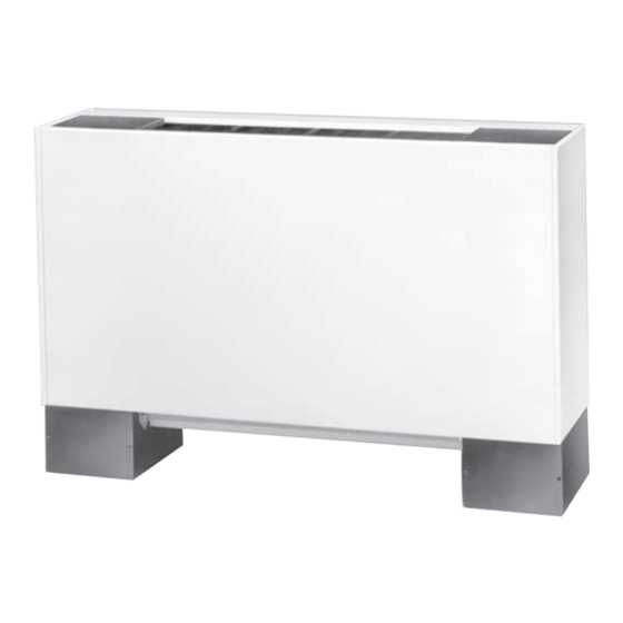
Cabinet Styles Model A Vertical Concealed Model B Vertical Cabinet Model C Horizontal Concealed Model D Horizontal Cabinet Model E Horizontal Recessed Model F Wall Hung Cabinet** UNT-IOM-6... - Page 5 Model J Model H Vertical Slope Top Cabinet Vertical Recessed Model L Model K Low Vertical Cabinet* Low Vertical Concealed* Model M Inverted Vertical Cabinet** Model N Inverted Vertical Recessed** *Fan-coil only **Force Flo cabinet heater only UNT-IOM-6...
-
Page 6: Model Number Description
® Each UniTrane fan-coil and Force Flo ™ cabinet heater has a Model Number multiple character model number unique to that particular unit. To Description determine a unit’s specific options, reference the model number on the unit nameplate on the fan scroll. The unit... - Page 7 Model Number Description With piping, RH Keylock panel & access door Digits 1 & 2 Unit Type With piping, LH w/leveling feet With piping, RH, ext. end pocket With piping, RH, ext. end pocket Digit 17 Motor Digit 3 Model Free discharge Digits 10 &...
- Page 8 With disconnect 10.0 Digit 30 Control Type Digit 26 Filter 11.0 Fan Speed Switch None 12.0 1” TA TUC w/Trane ICS 1” TA pltd. media Tracer ® ZN.010 1” TA + 1 extra Tracer ® ZN.510 1” TA pltd. media + 1 extra Digit 41 Auxiliary Auto Circuit Setter GPM ®...
-
Page 9: Receiving And Handling
Request an immediate joint inspection of the damage by the carrier and consignee. 7. Notify the Trane sales representative of the damage and arrange for repair. Have the carrier inspect the damage before begin- ning any repairs to the unit. -
Page 10: Jobsite Storage
IAQ problems, store the unit indoors. If indoor storage is not possible, the Trane Company makes the following provisions for outdoor storage: 1. Place the unit(s) on a dry surface or raised off the ground to assure adequate air circulation beneath unit and to assure that no portion of the unit contacts standing water at any time. -
Page 11: Installation Considerations
Touch up painted panels if necessary. If panels need paint, sanding is not necessary. However, clean the surface of any oil, grease, or dirt residue so the paint will adhere. Purchase factory approved touch up epoxy paint from your local Trane Service Parts Center and apply. UNT-IOM-6... -
Page 12: Service Access
Service Service access is available from the front on vertical units and from the bottom on horizontal units. Cabinet and recessed units have Access removable front or bottom panels to allow access into the unit. See Figure 3 for recommended service and operating clearances. Units have either right or left hand piping. -
Page 13: Installation Checklist
Installation Checklist The following checklist is only an abbreviated guide to the detailed installation procedures given in this manual. Use this list to ensure all necessary procedures are complete. For more detailed information, refer to the appropriate sections in this manual. WARNING: Allow rotating fan to stop before servicing equipment. - Page 14 9. Complete condensate drain line connections on fan-coil units. 10. Install automatic changeover sensor option on the supply water line. 11. Install automatic electric heat lockout switch option on the supply water line. 12. Install condensate overflow switch option correctly on the auxiliary drain pan.
-
Page 15: Vertical Units
Installing the Unit Before beginning installation, refer to Table 1 on page 17 for unit weights and Figure 3 on page 12 for service and operating clearances. In addition, refer to the unit submittal for installation details. CAUTION: Do not allow electrical wire to fall between the unit and installation surface. -
Page 16: Horizontal Units
4. Insert the threaded rods or lag screws in the wall before setting the unit in place. 5. Remove the front panel (cabinet unit only) by lifting it upward. 6. Position the hanger holes, located on the back of the unit, over the rod or lag screw heads, pushing the unit downward to properly position. - Page 17 2. Position and install the suspension rods or a suspension device (supplied by installer) according to the unit size dimensions in Figure 4 on page 15. Also refer to the weight range chart given in Table 1. 3. On cabinet units, remove the bottom panel by using a 5/32 inch Allen wrench to unscrew fasteners.
- Page 18 Cabinet units: Install the bottom panel by placing the hinged end on the unit’s hinged end (always at the return end of the unit). See Figure 4 on page 15 for keyslot hanger hole locations. Swing the panel upward into position. Tighten the panel to the unit with the fasteners provided.
- Page 19 Figure 5. Trim ring assembly installation. UNT-IOM-6...
-
Page 20: External Insulating Requirements
Requirements site for microbial growth (mold) causing unpleasant odors and health- related indoor air quality (IAQ) problems. The Trane Company recommends field-insulation of the following areas to prevent potential condensate and IAQ problems: 1. Supply and return water piping connections 2. -
Page 21: Units With Hydronic Coil Connec- Tions Only
Piping Before installing field piping to the coil, consider the following . Units with Hydronic Coil • All coil connections are 5/8 inch O.D. (or 1/2 inch nominal) female Connections Only copper connections. Piping Considerations • The supply and return piping should not interfere with the auxiliary drain pan or condensate line. -
Page 22: Units With Steam Coils
Note: For vertical fan-coil units, push the main condensate drain hose and overflow condensate drain hose through to the inside of the chassis end panel to prevent them from being burned when making sweat connections. Be sure to pull the hoses back through and route to the auxiliary drain pan when the end panel has cooled. - Page 23 This provides sufficient hydrostatic head pressure to overcome trap losses and ensure complete conden- sate removal. b. Trane Company recommends using flat and thermostatic traps because of gravity drain and continuous discharge operation. c. Use float and thermostatic...
-
Page 24: Factory Piping Package Connections
Before installing water piping supply and return lines to factory Factory Piping piping package, note the following items. Package • All piping connections are 5/8 inch O.D. (1/2 inch nominal) female Connections copper connections. Piping Considerations • The fan-coil supply and return piping should not interfere with the auxiliary drain pan or condensate line. -
Page 25: Installing The Auxiliary Drain Pan
Installing the The auxiliary drain pan ships loose with a fan-coil unit with factory piping. To install the auxiliary drain pan, insert the tabs, located on Auxiliary Drain the side of the drain pan, into the slots located in the chassis end panel. -
Page 26: Condensate Overflow Detection Device
inch inside diameter flexible plastic tube over the nipple and secure with a field supplied hose clamp. Note: The installer is responsible for adequately insulating field piping. See the “External Insulating Requirements section on page 20 for more information. The condensate overflow detection device is an option on fan-coil Condensate units with either a Tracer ®... -
Page 27: Automatic Electric Heat Lockout Switch (Fan-Coil)
When using field supplied 3-way valves, position the changeover sensor upstream of the valve on the supply water pipe. Recommendation: When using field supplied 2-way control valves, attach the changeover sensor in a location that will detect an active water temperature. The unit must always be able to sense the correct system water temperature, regardless of the control valve... - Page 28 The hydronic coil contains a vent, either manual or automatic, to Venting the Hydronic release air from the unit. This vent is not sufficient for venting the Coil water piping system in the building. Locate the coil air vent on the piping side, above the coil connections on the unit.
- Page 29 The manual circuit setter valve is an optional end valve supplied on Balancing The Manual the return pipe of the factory piping package. The valve allows the Circuit Setter Valve operator to regulate water flow through the hydronic coil, balance the water flow through the unit with other units in the piping system, and serves as a shutoff or end valve.
- Page 30 securely set the open memory position. The memory stop indicates the last set open position. 7. If using a 3-way valve: close the control valve to the coil, with the differential pressure meter still connected. This will divert flow to the bypass side of a 3-way valve.
- Page 31 The automatic flow valve is an Balancing The Auto- optional end valve on the return of matic Circuit Setter the factory piping package. Valve See Figure 20. The valve regu- lates water flow through the coil to a specific (gpm) flow rate, as ordered by the customer.
-
Page 32: Ductwork Recommendations
A one-inch duct collar is provided on units with a ducted return and/or discharge to attach ductwork to the unit. The Trane Company recommends using galvanized sheet metal ductwork with fan-coil and cabinet heater units. Slide the sheetmetal duct over the duct collar flange of the unit, seal the joint and fasten with sheetmetal screws. -
Page 33: Supply Power Wiring
Electrical Connections Refer to the unit nameplate to obtain the minimum circuit ampacity Supply Power (MCA) and maximum fuse size (MFS) or maximum circuit breaker Wiring (MCB) to properly size field supply wiring and fuses or circuit break- ers. See Figure 2 on page 6 to reference the nameplate location. Refer to the unit operating voltage listed on the unit wiring schematic, submittal, or nameplate. - Page 34 All field wiring should conform to NEC and all applicable state and local code require- ments. The control panel box is always on the end opposite the piping connections. Access the control box by removing the two screws that secure the front cover. If the unit has a terminal unit control board (TUC), remove the screw in the top right corner of the...
-
Page 35: Wall Mounted Control Interconnection Wiring
All sensor and input circuits are normally at or near ground (common) Electrical ® potential. When wiring sensors and other input devices to the Tracer Grounding ZN.010, ZN.510, ZN.520 or TUC, avoid creating ground loops with Restrictions grounded conductors external to the unit control circuit. Ground loops can affect the measurement accuracy of the controller. -
Page 36: Fan Mode Switch
Installing Wall Mounted Controls Wall mounted controls, which include the fan mode switch and the zone sensor module, ship loose inside the unit accessory bag. Position the controller on an inside wall 3 to 5 feet above the floor and and at least 18 inches from the nearest outside wall. -
Page 37: Zone Sensor Installation
Follow the procedure below to install the zone sensor module. Zone Sensor Reference Figure 25 on page 38 when installing the wall mounted Installation zone sensor. 1. Note the position of the setpoint adjustment knob and gently pry the adjustment knob from the cover using the blade of a small screwdriver. - Page 38 Wall mounted zone sensor Split-mounted option: Model # Digit 31 = W Wall mounted setpoint dial with unit mounted fan mode switch Model # Digit 31 = X Figure 25. Wall mounted zone sensor dimensions. Figure 26. Resistance temperature curve for the zone sensor, entering water temperature sensor, and discharge air sensor.
-
Page 39: Fan Mode Switch
Fan Mode Switch Manual Fan Mode Switch The manual fan mode switch is available for fan-coil units that do not have Trane factory-mounted control packages. This four-position switch (off-hi-med-lo) allows manual fan mode selection and is available unit or wall mounted. -
Page 40: Tracer® Zn.010 And Zn.510
® Tracer ZN.010 and ZN.510 ® Tracer ZN.010 and ZN.510 The Tracer ® ZN.010 is a stand-alone device that controls fan-coils and cabinet heaters. The Tracer ® ZN.510 can be stand-alone or utilize peer-to-peer commu- nications. The controller is easily accessible in the control end panel for service. -
Page 41: Information
® Tracer ZN.010 and ZN.510 When 24 VAC power is initially applied to the Tracer ® ZN.010 or Operating ZN.510, the following sequence occurs: Information 1. All outputs are controlled off. Power-Up Sequence 2. Tracer ® ZN.010 and ZN.510 reads all input values to detemine initial values. -
Page 42: Binary Inputs
® Tracer ZN.010 and ZN.510 Binary Inputs The factory hard wires the low temperature detection sensor to binary ® input #1 (BIP1) on the Tracer ZN.010 and ZN.510. The sensor BIP1: Low defaults normally closed (N.C.), and will trip off the unit on a low Temperature temperature diagnostic when detecting low temperature. -
Page 43: Binary Outputs
® Tracer ZN.010 and ZN.510 Table 5. Occupancy Sensor State Table Sensor Type Sensor Position Unit Occupancy Mode Normally Open Open Occupied Normally Open Closed Unoccupied Normally Closed Open Unoccupied Normally Closed Closed Occupied Binary Outputs Table 6. Binary Outputs Binary Output Description BOP1... -
Page 44: Analog Inputs
® Tracer ZN.010 and ZN.510 Both Tracer ® ZN.010 and ZN.510 accept a maximum of five analog Analog Inputs inputs. Reference Table 7. Table 7. Analog Inputs Analog Input Description Application Zone Space temperature Space temperature detection Local setpoint Thumbwheel setpoint Fan mode input Zone sensor fan switch Analog input 1 (AI1) -
Page 45: Supply Fan Operation
® Tracer ZN.010 and ZN.510 Reference Table 8 on page 45 for fan mode operation. Supply Fan ® The Tracer ZN.010 and ZN.510 will operate in either continuous fan Operation or fan cycling mode. The fan cycles when the fan mode switch is placed in auto. -
Page 46: Led Activity
Someone is pressing the service button or the controller has failed. power is applied to the controller LED flashes once every second Use Rover™, Trane’s service tool, to restore the unit to normal operation. Refer to the Rover™ product literature for more information. UNT-IOM-6... -
Page 47: Yellow Comm Led
® Tracer ZN.010 and ZN.510 Green STATUS LED The green LED normally indicates whether the controller is powered on (24 VAC supplied). Reference Table 11. Table 11. Green STATUS LED Activity Green LED Blink Activity Description LED on continuously Power on (normal operation) LED blinks once Manual output test mode LED blinks twice... -
Page 48: Manual Output Test
® Tracer ZN.010 and ZN.510 The purpose of the manual output test sequence is to verify output Manual Output and end device operation. Use the manual output test to: Test • Verify output wiring and operation without using Rover™, service tool. •... - Page 49 ® Tracer ZN.010 and ZN.510 Table 13. Test Sequence for 1-Heat /1-Cool Configurations Steps Cool Output Heat Output Damper BOP1-3 BOP4 (1) BOP5 BOP6 1. Off Closed 2. Fan High High Closed 3. Fan Medium Medium Closed 4. Fan Low Closed 5.
-
Page 50: Diagnostics
® Tracer ZN.010 and ZN.510 Diagnostics Table 14. Controller Diagnostics Diagnostic Latching Valves Elect. Heat Damper Yes/No Auxiliary Enabled No action No action No action temp. failure Condensate Closed Closed overflow detection Entering Enabled Enabled Enabled Enabled water temp. failure Fan mode Enabled Enabled... -
Page 51: Resetting Diagnostics
1. Automatic reset by the controller 2. By initiating a manual output test at the controller 3. By cycling power to the controller 4. Through Rover™, Trane’s service tool The controller includes an automatic diagnostic reset function which Automatic Reset by... - Page 52 ® Tracer ZN.010 and ZN.510 Rover™, Trane’s service tool, can reset diagnostics present in the Trane’s Service Tool, controller. For complete information about Rover™, refer to Trane Rover™ publication EMTX-IOP-2 Rover Installation, Operation and Program- ming Guide. Alarm Reset Any device that can communicate alarm reset information can reset diagnostics present in the controller.
-
Page 53: Troubleshooting
® Tracer ZN.010 and ZN.510 Troubleshooting Table 15. Fan Outputs do not Energize Probable Cause Explanation Random start After power-up, the controller always observes a random start that varies observed between 0 and 25 seconds. The controller remains off until the random start time expires. - Page 54 ® Tracer ZN.010 and ZN.510 Table 16. Valves Stay Closed Probable Cause Explanation Normal operation The controller opens and closes the valves to meet the unit capacity require- ments. Requested mode: off It is possible to communicate the operating mode (such as off, heat, and cool) to the controller.
- Page 55 ® Tracer ZN.010 and ZN.510 Table 17. Valves Stay Open Probable Cause Explanation Normal operation The controller opens and closes the valves to meet the unit capacity require- ments. Valve override The controller can communicate a valve override request to affect the valve operation.
- Page 56 ® Tracer ZN.010 and ZN.510 Table 18. Electric Heat Not Operating Probable Cause Explanation Normal operation The controller cycles electric heat on and off to meet the unit capacity require- ments. Requested mode: off It is possible to communicate the operating mode (such as off, heat, cool) to the controller.
- Page 57 ® Tracer ZN.010 and ZN.510 Table 19. Fresh Air Damper Stays Closed Probable Cause Explanation Normal operation The controller opens and closes the fresh air damper based on the controller’s occupancy mode and fan status. Normally, the fresh air damper is open during occupied mode when the fan is running and closed during unoccupied mode.
- Page 58 ® Tracer ZN.010 and ZN.510 Table 20. Fresh Air Damper Stays Open Probable Cause Explanation Normal Operation The controller opens and closes the fresh air damper based on the controller’s occupancy mode and fan status. Normally, the fresh air damper is open during occupied mode when the fan is running and closed during unoccupied mode.
- Page 59 Low/Med/High: The fan will run continuously at the selected speed and the valve option will cycle to meet setpoint. For Tracer ® ZN.520 controlled units that will interface with the Trane Tracer Summit ® building management system, terminate the commu- nication wiring in the control box at the designated terminals on the ®...
- Page 60 (provided with the Rover service tool) to the telephone style RJ11 connection on the zone sensor module. Attach the other end of the cable to a laptop computer running Trane Rover software to establish communication. Zone Sensors Without...
- Page 61 ® Tracer ZN.520 ® Tracer ZN.520 Unit Refer to the Trane publication, CNT-IOP-2 Installation Operation and Start-Up Programming Guide, to operate the Tracer ® ZN.520 with Trane Integrated Comfort™ System (ICS). The factory pre-programs the ® Tracer ZN.520 with default values to control the temperature and unit ®...
- Page 62 ® Tracer ZN.520 Occupied When the controller is in the occupied mode, the unit attempts to maintain the space temperature at the active occupied heating or cooling setpoint, based on the measured space temperature, the discharge air temperature, the active setpoint, and the proportional/ integral control algorithm.
- Page 63 The controller can be placed in occupied bypass mode by either communicating an occupancy request of Bypass to the controller or by using the timed override On button on the Trane zone sensor. When the controller is in unoccupied mode, you can press the On...
- Page 64 ZN.520 lockouts (latching diagnostics) are manually reset whenever the fan mode switch is set to the off position or when power is restored to the unit. The last diagnostic to occur is retained until the unit power is disconnected. Refer to Trane publication, CNT-IOP-2 ® Tracer ZN.520 Installation Operation and Programming Guide, for...
- Page 65 ® Tracer ZN.520 operation. The Tracer ® ZN.520 controller operates the supply fan continuously when the controller is in the occupied and occupied standby modes, for either heating or cooling. The controller only cycles the fan off with heating and cooling capacity in the unoccupied mode. The economizer is used for cooling purposes whenever the outdoor temperature is below the economizer enable setpoint and there is a need for cooling.
- Page 66 ® Tracer ZN.520 Unit diagnostics can affect the Tracer ® ZN.520 controller operation, causing unit operation to be defined as abnormal. Refer to the Troubleshooting section for more information about abnormal unit operation. The heating output is controlled based on the heating capacity. At 0% capacity, the heating output is off continuously.
- Page 67 ® Tracer ZN.520 During dehumidification, when the fan is on Auto, the fan speed can switch depending on the error. Fan speed increases as the space temperature rises above the active cooling setpoint. Table 21. Fan Configuration Auto fan operation Fan speed default Heating Continuous Medium...
- Page 68 ® Tracer ZN.520 Table 24. Fan operation in heating and cooling modes Heating Cooling Fan mode Occ. Unocc. Occ. Unocc. Off/High Off/High Medium Off/High Off/High High High Off/High High Off/High Auto (continuous) Default Off/High Default Off/High fan sp. fan sp. Continuous Fan During occupied and occupied standby modes, the fan normally is on.
- Page 69 ® Tracer ZN.520 ® Fan Start on High Speed On a transition from off to any other fan speed, the Tracer ZN.520 controller automatically starts the fan on high speed and runs the fan at high speed for 0.5 seconds. This provides the ample torque required to start all fan motors from the off position.
- Page 70 ® Tracer ZN.520 warm enough to heat when it is five degrees above the measured space temperature. When the controller invokes the entering water temperature sampling function, the unit opens the main hydronic valve for no more than three minutes before considering the measured entering water temperature.
- Page 71 ® Tracer ZN.520 to expose the damper stop screw on the control panel end. Relocate the stop screw to the appropriate position. Then loosen the stop screw wingnut and adjust the linkage. Economizer Damper With a valid outdoor air temperature (either hardwired or communi- cated), Tracer ®...
- Page 72 (with communica- tion wiring between units) and building automation system applica- tions. For this application you will need to use the Rover service tool. For more information on setup, refer to the Trane publication EMTX- IOP-2. Binary Inputs The Tracer ®...
- Page 73 ® Tracer ZN.520 Table 26. Binary Input Configurations Binary Controller operation Input Description Configuration Contact closed Contact open BI 1 Low temperature Normally closed Normal Diagnostic detection (Note 1) (note 5) BI 2 Condensate overflow (Note 1) Normally closed Normal Diagnostic (note 5) BI 3...
- Page 74 ® Tracer ZN.520 Binary Outputs Binary outputs are configured to support the following: • Three fan stages (when one or two fan stages are present, medium fan speed can be configured as exhaust fan) • One hydronic cooling stage • One hydronic heating stage (dehumidification requires this to be in the reheat position) •...
- Page 75 ® Tracer ZN.520 Analog Inputs Table 28. Analog Inputs Description Terminals Function Range Zone TB3-1 Space temperature input 5° to 122°F (-15° to 50°C) Ground TB3-2 Analog ground TB3-3 Setpoint input 40° to 115°F (4.4° to 46.1°C) TB3-4 Fan switch input 4821 to 4919 W (Off) 2297 to 2342 W (Auto) 10593 to 10807 W (Low)
- Page 76 • Timed override (On) and Cancel timed override • Communication jack Space Temperature Trane zone sensors use a 10kW thermistor to measure the space Measurement temperature. Typically, zone sensors are wall-mounted in the room and include a space temperature thermistor. As an option, the zone sensor can be unit-mounted with a separate space temperature thermistor located in the unit’s return air stream.
- Page 77 ® Tracer ZN.520 These setpoint limits only apply to the occupied and occupied standby heating and cooling setpoints. These setpoint limits do not apply to the unoccupied heating and cooling setpoints stored in the controller’s configuration. When the controller is in unoccupied mode, it always uses the stored unoccupied heating and cooling setpoints.The unit can also be configured to enable or disable the local (hardwired) setpoint.
- Page 78 Typically, a communication link is applied between unit controllers and a building automation system. Communication also is possible via Rover, Trane’s service tool. Peer-to-peer communication across controllers is possible even when a building automation system is not present.You do not need to observe polarity for Comm5 communication links.
- Page 79 ® Tracer ZN.520 Diagnostics ® Table 30. Tracer ZN.520 Diagnostics Diagnostic Other Outputs (Note 1) Condensate overflow Valves Closed, Fresh air damper Closed, electric heat Off, Baseboard heat Off Low temperature detection Valves Open, Fresh air damper Closed, electric heat Off, Baseboard heat Off Low air flow - fan failure Valves Closed, Fresh air damper Closed, electric heat Off,...
- Page 80 ® Tracer ZN.520 Note 3: When the outdoor air temperature sensor has failed or is not present, the Tracer ® ZN.520 controller generates a diagnostic to indicate the sensor loss condition. The controller automatically clears the diagnostic once a valid outdoor air temperature value is present (non-latching diagnostic).
- Page 81 ® Tracer ZN.520 If a Low Temperature Detection diagnostic recurs within 24 hours after an automatic diagnostic reset, you must manually reset the diagnos- tic. See other possible methods for resetting diagnostics in this section. Manual output test: You can use the Test button on the controller either during installation to verify proper end device operation or during troubleshooting.When you press the Test button, the controller exercises all outputs in a predefined sequence.
- Page 82 ® Tracer ZN.520 Table 31. Red Service LED Activity LED Operation LED Activity Description Red Service LED Off continuously after Normal operation power is applied to the controller. On continuously, even when Someone is pressing the Service power is first applied to the button or the controller has failed.
-
Page 83: Tracer® Zn.520
® Tracer ZN.520 Troubleshooting Green Status LED Table 32. Green Status LED activity Green LED activity Description On continuously Power on (normal operation) Blinks (one blink) The controller is in manual output test mode. No diagnostics present. Blinks (2 blinks) The controller is in manual output test mode. - Page 84 ® Tracer ZN.520 Manual Output Test The procedure for testing is: 1.Press and hold the Test button for at least two seconds, then Test Sequence release the button to start the test mode. When manual output test mode begins, the controller turns off all outputs and calibrates modulating end devices closed.
-
Page 85: Troubleshooting
Fan mode off When a local fan mode switch (provided on the Trane zone sensor) determines the fan operation, the off position controls the unit off. Requested mode off You can communicate a desired operating mode (such as off, heat, and cool) to the controller. - Page 86 Refer to the Manual Output Test section. Fan mode off When a local fan mode switch (provided on the Trane zone sensor) determines the fan operation, the off position controls the unit off and valves to close.
- Page 87 Terminal Unit Control (TUC) The TUC is capable of operating in either a standalone application or interfacing with a Trane ® Tracer system. In addition, Trane EveryWare ™ software is available to edit the configuration of the TUC. The TUC board is easily access- ible on an isolation panel in the control panel.
-
Page 88: Tracer Communication Wiring
Terminal Unit Control (TUC) ® ® For TUC controlled units that will interface with the Trane Tracer Tracer system or Tracer Summit ® building management system, terminate Communication the communication wiring in the control box at the designated Wiring terminals on the low voltage terminal strip. Reference the unit wiring schematic or submittals. -
Page 89: Service Communication Wiring
Maintain the correct polarity throughout the communication wiring circuit. Once wiring is complete, use Trane EveryWare ™ software to commu- nicate to the TUC. The comm4 connection can be made by the telephone style RJ 11 connector (Western Electric #616 or equivalent) on the zone sensor module and the computer using EveryWare ™... -
Page 90: Tuc Human Interface
Terminal Unit Control (TUC) 3. Rotate the setpoint dial on the zone sensor module to 55 ° F for cooling or 85 ° F for heating. The appropriate control valve will actuate assuming the following conditions: • Room temperature should be greater than 55 ° F and less than 85 °... - Page 91 Terminal Unit Control (TUC) Table 37. Valid TUC Addresses DIP Switch Position DIP Switch Position Address 1 2 3 4 5 6 7 8 Address 1 2 3 4 5 6 7 8 X X X X X X X X X X X X X X X X X X X X...
-
Page 92: Cooling And Heating Operation
The last diagnostic to occur is retained until the unit power is disconnected. Refer to Trane publication, EMTX-IOP-1 TUC Installation Operation and Programming Guide, for specific instructions regarding the procedure for running the TUC. -
Page 93: Fan Mode Operation
Terminal Unit Control (TUC) high or low temperatures. In addition, the TUC calculates the heating setpoint equal to the cooling setpoint minus an adjustable heating offset. Furthermore, the heating setpoint cannot exceed a value less than or equal to the cooling setpoint. The TUC is in the cooling mode when the space temperature rises 1 °... -
Page 94: Entering Water Temperature Sampling Function
Terminal Unit Control (TUC) The entering water temperature sampling function allows water to Entering Water circulate in an attempt to sense water cold enough to provide cooling. Temperature The function uses a timer to permit the controller and the valve to fully Sampling Function open while the water circulates for 3 minutes. -
Page 95: Fresh Air Damper Options
Terminal Unit Control (TUC) Note: The auxiliary electric heat option is not available with a four-pipe fan-coil unit. Fresh Air Damper Units with manual fresh air dampers ship with the damper in Options the closed position, which is Manual adjustable from zero to 100 percent in 25 percent incre- ments. - Page 96 Terminal Unit Control (TUC) the outside air temperature falls to 10 ° F or more below the zone temperature. The TUC will control the damper to a position to produce optimal cooling during economizing. If power is interrupted or the TUC is turned off, the damper will spring back to the closed position.
-
Page 97: Bip4: Low Temperature Detection Option
Terminal Unit Control (TUC) The low temperature detection BIP4: Low option protects the unit from Temperature freezing conditions by using a Detection Option capillary line in the coil fins to detect freezing conditions. The TUC uses the low temperature sensor with a normally open valve. -
Page 98: Bip4: Smoke Input
Terminal Unit Control (TUC) and the electric heat to disable. This creates an immediate shutdown ® latching diagnostic, which requires a manual or Tracer reset to resume normal operation. However, normal operation cannot resume until the water level recedes to an acceptable level. The switch will close after the water level recedes, and the active temperature control of the unit will resume by an automatic reset. -
Page 99: Bip2: Motion Detection
Terminal Unit Control (TUC) The motion detection input when used with a motion detection switch BIP2: Motion (installer supplied) detects the absence of motion in the space during Detection the occupied mode. If no motion is detected, the TUC controls the space to alternate heating and cooling setpoints while also controling the economizer damper option to the minimum position. - Page 100 Terminal Unit Control (TUC) Table 39. Autocycle Test Staging Stage LEDs (1) Fan-Coil Output Exercised Fan low speed Fan medium speed Fan high speed Economizer/damper Cooling valve Heating valve Electric heat stage 1 Electric heat stage 2 Not used Reheat Not used Not used Not used...
-
Page 101: Reading Diagnostics
Terminal Unit Control (TUC) Reading Diagnostics Use the TUC human interface to read the current unit diagnostic. If no diagnostics are present, the last diagnostic appears. Perform the following steps. Refer to Table 23 on page 72 for staging details. 1. -
Page 102: Reading The Operating Machine State
Terminal Unit Control (TUC) Table 40. Blink Sequence Corresponding Diagnostic Codes Sequence 1 Sequence 2 Sequence 3 Code Diagnostic Latch None Power failure None None Controller failure None None Condensate overflow Leaving water temp sensor 1 failure Zone and supply temp sensor failure High EWT Low EWT... - Page 103 Terminal Unit Control (TUC) 6. Read and record the operating machine state. Return the DIP switches to the initial positions recorded in step 1. Short the test inputs to set the address in the TUC EEPROM. Example: Operating Machine State for Standby Mode Sequence 1 Sequence 2 Sequence 3...
-
Page 104: Reading The Operating Control Mode
Terminal Unit Control (TUC) Using the human interface, read the operating control mode. Reading the Operating Control 1. Read and record the initial TUC address. Mode 2. Set the TUC DIP switch #5 and #7 to ON (address = 10). The remaining switches will be off. - Page 105 Terminal Unit Control (TUC) Sequence 1 Sequence 2 Sequence 3 Sequence 1 Sequence 2 Sequence 3 Table 42. Operating Control Mode LED Sequences and Codes Sequence 1 Sequence 2 Sequence 3 Code Control Definition Mode Stop Diagnostic, user switch, ® Tracer command or interlock has stopped the unit...
- Page 106 Terminal Unit Control (TUC) Table 42—Continued. Operating Control Mode LED Sequences and Codes Sequence 1 Sequence 2 Sequence 3 1 2 3 1 2 3 Code Control Definition Mode Cool Occupied cooling with the water coil Cool Occupied cooling with water econo- and 100% economizer mize...
-
Page 107: Resetting Diagnostics
Resetting There are five ways in which diagnostics are reset: Diagnostics 1. Using the zone sensor 2. Using Everyware™, Trane’s TUC service tool 3. By cycling power to the TUC 4. Through Tracer 100i ™ or 100L ™ ® 5. Through Tracer Summit Using the zone sensor’s fan mode switch to reset diagnostics, slide... -
Page 108: Unit Mode Listed As Standby
Terminal Unit Control (TUC) Remove the 24 VAC power from the board and then reapply it to Cycling Power to the cycle the unit through a power-up sequence. By default, the controller attempts to reset all diagnostics at power-up. ™ Using Tracer 100i The TUC editor’s reset failure point allows the user to reset controller diagnostics. -
Page 109: Troubleshooting
DIP switches, then short the TUC test input momentarily. Incorrect comm 4 wiring Verify that the link is twisted pair Trane part # 400-20-28 or equiva- lent. TUC (comm 4) wiring is polarity sensitive throughout the com- munication link. If possible, isolate the TUC from the rest of the ICS link to determine if the problem exists in the comm wiring or in the TUC board. - Page 110 Terminal Unit Control (TUC) Table 45—Continued. Fan Outputs not Energizing Probable Cause Explanation No power to the TUC The TUC requires 24 VAC power for the unit to operate properly. Autocycle test The controller includes an auto cycle test sequence that verifies analog and binary output operation and associated output wiring.
- Page 111 Terminal Unit Control (TUC) Table 46—Continued. Valves Closed Probable Cause Explanation Unit Configuration The TUC cannot control any valve outputs if the unit is configured for no valves. Also, if the valve type is incorrectly configured (on/off, modulating analog, or 3-wire floating point), the valve(s) may not operate properly.
- Page 112 Terminal Unit Control (TUC) Table 48. Electric Heat Not Operating Probable Cause Explanation Normal Operation The controller cycles electric heat on and off to meet the unit capacity requirements. Unit Disabled The TUC may be disabled via the shutdown mode on a Tracer ®...
- Page 113 Terminal Unit Control (TUC) Table 49. Fresh Air Damper Closed Probable Cause Explanation • The two-position fresh air damper opens under normal unit operation Normal Operation during occupied mode and closes during unoccupied mode. • Modulating analog and 3-wire floating point economizers open to the minimum position (configurable) when the unit is occupied and modulate to meet unit capacity requirements.
- Page 114 Terminal Unit Control (TUC) Table 50. Fresh Air Damper Open Probable Cause Explanation • The two-position fresh air damper opens under normal unit opera Normal Operation tion during occupied mode and closes during unoccupied mode. • Modulating analog and 3-wire floating point economizers open to the minimum position (configurable) when the unit is occupied and modulate to meet unit capacity requirements.
- Page 115 Table 52. Zone Temperature Too Cool Probable Cause Explanation Active Heating/Cooling Setpoints Verify that the active heating/cooling setpoints are reasonable. It is ® possible for either the zone sensor or for the Tracer system to send heating and cooling setpoints to the TUC. Use the Tracer ®...
-
Page 116: Maintenance Procedures
Maintenance Listed below are the recommended maintenance schedules. Instruc- Periodic tions for specific maintenance procedures are given in the sections Maintenance following the checklist. Checklist WARNING: Allow rotating fan to stop before servicing equipment. Failure to do so may cause severe personal injury or death. - Page 117 Note: Vertical recessed, horizontal cabinet, & horizontal recessed units with a bottom return have filter guides to secure the filter in position. Also, if these unit types have a fresh air opening, they require an additional filter for the fresh air opening. 2.
-
Page 118: Inspecting And Cleaning Drain Pans
Clean the fan-coil unit’s main and auxiliary drain pans to ensure the Inspecting and unit drains condensate properly. Cleaning Drain Pans Check the condensate drain pan and drain line to assure the conden- sate drains properly at least every six months or as dictated by operating experience. - Page 119 Auxiliary Drain Pan 1. To remove the auxiliary drain pan, loosen the hose clamp (installer supplied) around the drain con- nection collar and disconnect the drain line. 2. Remove the overflow drain line to the auxiliary drain pan if it was installed.
-
Page 120: Winterizing The Coil
Vertical units: To remove the main drain pan on vertical fan-coil units, disconnect the clips holding the pan to the fanboard. Disconnect the main and overflow drain hoses and slide pan forward to remove. See Figure 33. Figure 33. To remove the main drain pan on vertical fan-coil units, disconnect the clips holding the pan to the... -
Page 121: Inspecting And Cleaning Coils
Inspect coils at least every six months or more frequently as dictated by operating experience. Required cleaning frequency depends on the system operating hours, filter maintenance and efficiency, and dirt load. The Trane Company recommends the following method of cleaning coils: 1. Disconnect all electrical power to the unit. - Page 122 Table 54. Factory Piping Package Volumes, oz. (mL) Piping Package Volume Main coil 6 (178) Auxiliary coil 12 (355) Table 55. Hydronic Coil Volumes/Heating & Cooling, gal. Unit Size Total # Rows Volume Note: 1-row coil refers only to the 1-row heating coil in some 4-pipe configurations.
-
Page 123: Inspecting And Cleaning The Internal Insulation On Fan-Coils
(e.g. closed- cell insulation or sheet metal surface). The Trane Company recommends the following procedure for proper cleaning the fan-coil internal insulation and sheet metal: 1. Disconnect all electrical power to the unit. -
Page 124: Inspecting And Cleaning The Fan
Inspect the fan at least every six months or more frequently if operat- ing experience dictates. Clean accumulated dirt and organic matter on the interior fan surface immediately. Inspecting and The Trane Company recommends the following procedure for cleaning Cleaning the Fan fan surfaces: 1. Disconnect all electrical power to the unit. - Page 125 7. Allow the unit to dry completely before putting it back into service. 8. Do not allow any contaminated material to contact other areas of the unit or building. Properly dispose of all contaminated materials and cleaning solution. If microbial growth (mold) is present, determine the cause of the contamination and take action to prevent reoccurance.
-
Page 126: Fan Board Assembly Removal
However, the motor itself cannot be repaired or rewound. If the motor fails, record the model number from the unit nameplate and present to the local Trane Service Parts Center to purchase a replacement. The motor bearings are perma- nently lubricated and do not require any further oiling. - Page 127 Trane Service Parts Center. To order, the Trane parts center will need the unit model number (which can be found on the unit nameplate), the serial number, and the part name or Table 56.
-
Page 128: Factory Piping Packages
Appendix Factory Piping Packages Automatic Circuit Setter (C) UNT-IOM-6... -
Page 129: Typical Wiring Diagrams
Fan Mode Switch Typical Wiring Diagram For Reference Only: This schematic shows typical wiring of a fan-coil. It is not intended for a basis of design or for equipment installation purposes in the field. For an as-built schematic specific to a particular unit, please see the ship-with schematic for that specific unit. - Page 130 This schematic shows typical wiring of a fan-coil. It is not intended for a basis of design or for equipment installation purposes in the field. For an as-built schematic specific to a particular unit, please see the ship-with schematic for that specific unit or contact your local Trane representative. Two-pipe autochangeover...
- Page 131 This schematic shows typical wiring of a fan-coil. It is not intended for a basis of design or for equipment installation purposes in the field. For an as-built schematic specific to a particular unit, please see the ship-with schematic for that specific unit or contact your local Trane representative. Two-pipe autochangeover with electric heat...
- Page 132 This schematic shows typical wiring of a fan-coil. It is not intended for a basis of design or for equipment installation purposes in the field. For an as-built schematic specific to a particular unit, please see the ship-with schematic for that specific unit or contact your local Trane representative. Four-pipe...
- Page 133 For an as-built schematic specific to a particular unit, please see the ship-with schematic for that specific unit or contact your local Trane representative. Two-pipe unit with a modulating valve Electric heat terminal unit controller Wall mounted zone sensor —...
-
Page 134: Typical Wiring Diagrams
For an as-built schematic specific to a particular unit, please see the ship-with schematic for that specific unit or contact your local Trane representative. Four-pipe unit with control valves (both modulating) terminal unit controller Wall mounted zone sensor —... - Page 135 UNT-IOM-6...
- Page 136 Stocking Location LaCrosse Worldwide Applied Systems Group 3600 Pammel Creek Rd. LaCrosse, WI 54601-7599 www.trane.com Since The Trane Company has a policy of continuous product improvement, it reserves the right to An American Standard Company change design and specifications without notice.
Need help?
Do you have a question about the UniTrane and is the answer not in the manual?
Questions and answers