Sign In
Upload
Manuals
Brands
Trane Manuals
Heater
UniTrane
Trane UniTrane Manuals
Manuals and User Guides for Trane UniTrane. We have
3
Trane UniTrane manuals available for free PDF download: Installation, Operation And Maintenance Manual, Installation Operation & Maintenance, Installation, Operation And Maintenance Instructions
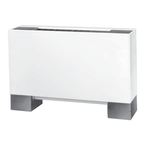
Trane UniTrane Installation, Operation And Maintenance Manual (164 pages)
200-1200 CFM Fan Coil, Cabinet Heater, Low Vertical Models
Brand:
Trane
| Category:
Heater
| Size: 18.53 MB
Table of Contents
Table of Contents
4
Model Number Descriptions
5
Unitrane™ Fan Coil/Force Flo™ Cabinet Heater
5
Unitrane™ Fan Coil Low Vertical Model
8
General Information
10
Pre-Installation
11
Receiving and Handling
11
Jobsite Storage
11
Site Preparation
12
Dimensions and Weights
13
Service Clearances
13
Component Data
14
Available Models
15
Coil Connections
41
Fresh Air Opening Locations
45
Vertical Units
46
Wall Box
47
Projection Panel
48
Installation-Mechanical
49
Installation Checklist
49
Installing the Unit
50
Duct Connections
52
Coil Piping and Connections
53
Piping Package Components
54
Hydronic Coil Piping
54
Water Piping Connections
54
Condensate Drain Connections
55
External Insulating Requirements
56
Balancing Manual Circuit Setter Valve
57
Installation - Electrical
60
Unit Wiring Diagrams
60
Supply Power Wiring
60
Electrical Grounding Restrictions
60
Interconnection Wiring
60
MCA and MOP Calculations
61
ECM Overview and Setup
65
Overview
65
Electronically Commutated Motor (ECM)
65
Velocitach Motor Control Board
66
Installation and Initial Setup
67
Adjustments
72
Configurations
75
Installation - Controls
80
Control Options
80
Installation - Controllers
84
Tracer® ZN010 and ZN510 Controllers
84
Tracer® ZN520 Controller
84
Tracer® UC400-B Controller
85
Power Supply
87
Air-Fi® Wireless Communications System
89
Specifications
90
Zone Sensor Options
91
Zone Sensor Installation
92
Zone Sensor Settings
95
Sensor Operations
97
Wireless Sensor Specifications
98
Agency Compliance
99
Wireless Display Sensor (WDS)
99
Error Codes
102
Startup
103
Pre-Startup Checklist
103
Unit Startup
104
Tracer® ZN010/ZN510 Controllers
104
Tracer® ZN520 Controllers
106
Heating Operation
108
Fan Mode Operation
109
Tracer® UC400-B Controller
114
Sequence of Operation
115
Fan Operation
117
Routine Maintenance
122
Maintenance Checklist
122
Air Filters
122
Coils
123
Control Device Replacement
125
Drain Pans
125
Fans
127
Diagnostics and Troubleshooting
130
Fan Coil and Cabinet Heater
130
Wireless Zone Sensors (WZS)
131
Servicing/Testing Wireless Zone Sensors
136
ZN010, ZN510, and ZN520 Controllers
137
Tracer® UC400-B Controller
143
ECM Motors
150
Wiring Diagrams
156
Advertisement
Trane UniTrane Installation, Operation And Maintenance Instructions (132 pages)
Fan-Coil and Air Conditioners
Brand:
Trane
| Category:
Air Conditioner
| Size: 9.38 MB
Table of Contents
Table of Contents
4
Model Number Descriptions
7
General Information
10
Pre-Installation
11
Receiving and Handling
11
Jobsite Storage
11
Installation Preparation
12
Service Access
12
Pre-Installation Checklist
13
Dimensions and Weights
14
Available Models
16
Factory-Installed Piping Packages
17
Vertical Concealed, Model a
18
Vertical Cabinet, Model B
19
Horizontal Concealed, Model C
20
Horizontal Cabinet, Model D
21
Horizontal Recessed, Model E
22
Vertical Wall Hung Cabinet, Model F (Force-Flo Units Only)
23
Vertical Recessed, Model H
24
Vertical Slope Top, Model J
25
Low Vertical Concealed, Model K
26
Low Vertical Cabinet, Model L
27
Inverted Vertical Cabinet, Model M (Force-Flo Units Only)
28
Inverted Vertical Recessed, Model N (Force-Flo Units Only)
29
Fan-Coil Coil Connections, Vertical Units
30
Fan-Coil Coil Connections, Horizontal Units
30
Force-Flo Coil Connections, Vertical Units
31
Force-Flo Coil Connections, Horizontal Units
31
Force-Flo Coil Connections, Inverted Units
32
Fresh Air Opening Locations, Horizontal Units-Models C, D, and E
33
Fresh Air Opening Locations, Vertical Units-Models A, B, F, H, J, K, L, M, and N
34
Wall Box
35
Projection Panel
36
Installation-Mechanical
37
Duct Connections
37
Piping Considerations
37
Installation-General
48
Installing the Unit
48
Vertical Units
48
Horizontal Units
48
Cabinet Units
49
Recessed Units
49
Installation Checklist
50
Installation-Controls
52
General Information
52
Control Options (Including Factory-Installed)
52
Installing Wall-Mounted Wired Sensors
53
Location Considerations
55
Fan Mode Switch Installation
55
Wired Zone Sensor Installation
55
Installing Wall-Mounted Wireless Zone Sensors
56
General Information
56
Product Description
56
Dimensions
56
Location Considerations
57
Mounting the Sensor Back Plate
57
Replacing the Sensor Cover
58
Installation-Electrical
59
Unit Wiring Diagrams
59
Supply Power Wiring
59
Electrical Grounding Restrictions
59
Wall-Mounted Control Interconnection Wiring
60
Controls Interface
67
Wired Controllers-Communication Wiring
67
Units with Tracer ZN510 and ZN520 Only
67
Device Addressing
67
Recommended Communication Wiring Practices
67
Wireless Temperature Sensor
68
Address Setting
68
Observing the Receiver for Readiness to Associate
69
Associating the Sensor to the Receiver
70
Testing Signal Strength and Battery Status
70
Configuring the Wireless Display Sensor (Model WDS Only)
71
Replacing the Sensor Cover
75
Sensor Operations
75
Wireless Sensor Specifications
78
Pre-Start
81
Pre-Startup Checklist
81
Start-Up
83
Tracer™ ZN510 & ZN520 Unit Startup
83
General Information
83
Fan Mode Switch Operation
84
Tracer ZN010 & ZN510 Operation
84
Tracer ZN520 Operation
85
Sequence of Operation: Tracer ZN010 and ZN510
86
Binary Inputs
86
Binary Outputs
87
Zone Sensors
88
Supply Fan Operation
88
Tracer ZN520 Sequence of Operation
89
Cooling Operation
91
Heating Operation
91
Fan Mode Operation
92
Space Temperature Measurement
98
Maintenance
101
Maintenance Procedures
101
Periodic Maintenance Checklists
105
Diagnostics
107
Troubleshooting
113
Troubleshooting the Relay (Daughter) Board
113
Troubleshooting Wireless Controls
115
Troubleshooting Tracer ZN010, ZN510, and ZN520
124
Manual Output Test
125
Wiring Diagrams
126
CSTI Fan Speed Switch
126
CSTI Non Fan Speed Switch
127
Line Voltage Fan Speed Switch
128
Tracer ZN010 with Electric Heat
129
Tracer ZN510 with Main and Auxiliary Valves
130
ZN520 with 2-Stage Electric Heat
131
Trane UniTrane Installation Operation & Maintenance (136 pages)
Fan-Coil Room Conditioners Force Flo Cabinet Heaters Low Vertical Fan-Coils
Brand:
Trane
| Category:
Heater
| Size: 2.1 MB
Table of Contents
Table of Contents
2
General Information
3
Cabinet Styles
4
Unt-Iom
6
Model Number Description
6
Receiving and Handling
9
Jobsite Storage
10
Installation Considerations
11
Service Access
12
Installation Checklist
13
Vertical Units
15
Installing the Unit
15
Horizontal Units
16
External Insulating Requirements
20
Startup Checklist
20
Units with Hydronic Coil Connec- Tions Only
21
Piping
21
Units with Steam Coils
22
Factory Piping Package Connections
24
Installing the Auxiliary Drain Pan
25
Condensate Overflow Detection Device
26
Automatic Changeover Sensor
26
Automatic Electric Heat Lockout Switch (Fan-Coil)
27
Ductwork Recommendations
32
Duct Connections
32
Supply Power Wiring
33
Electrical Connections
33
Wall Mounted Control Interconnection Wiring
35
Electrical Grounding Restrictions
35
Fan Mode Switch
36
Installation
36
Installing Wall Mounted Controls
36
Zone Sensor Installation
37
Fan Mode Switch
39
Tracer® ZN.010 and ZN.510
40
Operating Information
41
Information
41
Binary Inputs
42
Binary Outputs
43
Analog Inputs
44
Fan Mode Switch
44
Zone Sensors
44
Supply Fan Operation
45
LED Activity
46
Troubleshooting
46
Yellow COMM LED
47
Manual Output Test
48
Diagnostics
50
Resetting Diagnostics
51
Troubleshooting
53
Tracer® ZN.520
83
Troubleshooting
85
Tracer Communication Wiring
88
Service Communication Wiring
89
Wall-Mounted Zone Sensor Module
89
TUC Human Interface
90
Cooling and Heating Operation
92
TUC Sequence of Operation
92
Fan Mode Operation
93
Entering Water Temperature Sampling Function
94
2-Pipe with Auxiliary Electric Heat (Fan-Coils)
94
Fresh Air Damper Options
95
BIP4: Low Temperature Detection Option
97
BIP3: Condensate Overflow Detection Device
97
BIP4: Smoke Input
98
BIP1: External Interlock
98
BIP3: Occupied/Unoccupied Mode
98
BIP2: Motion Detection
99
Autocycle Test
99
Reading Diagnostics
101
Reading the Operating Machine State
102
Reading the Operating Control Mode
104
Resetting Diagnostics
107
Diagnostics
107
Unit Mode Listed as Standby
108
Troubleshooting
109
Maintenance Procedures
116
Periodic Maintenance Checklist
116
Maintenance
116
Inspecting and Cleaning Drain Pans
118
Winterizing the Coil
120
Inspecting and Cleaning Coils
121
Inspecting and Cleaning the Internal Insulation on Fan-Coils
123
Inspecting and Cleaning the Fan
124
Fan Board Assembly Removal
126
Factory Piping Packages
128
Appendix
128
Typical Wiring Diagrams
129
Typical Wiring Diagrams
134
Advertisement
Advertisement
Related Products
Trane UniTrane Fan-Coil
Trane UHAA-15
Trane UHAA-02
Trane UHAA-03
Trane UHAA-04
Trane UHAA-48
Trane UHEC-IM-7A
Trane UHSB
Trane UHPB
Trane UniTrane Fan Coil
Trane Categories
Air Conditioner
Heat Pump
Chiller
Air Handlers
Furnace
More Trane Manuals
Login
Sign In
OR
Sign in with Facebook
Sign in with Google
Upload manual
Upload from disk
Upload from URL