
Related Manuals for Xantrex RV2012GS


Summary of Contents for Xantrex RV2012GS
- Page 1 RV2012GS RV2012GS-15/20B 3341 RV2012GS-20B RV2512GS RV3012GS Owner’s Manual RV GS Series Inverter/Charger...
-
Page 3: About This Manual
RV Series Inverter/Charger models RV2012GS, RV2012GS-15/ 20B, RV2012GS-20B, RV2512GS, RV3012GS. It does not provide details about particular brands of batteries. You need to consult individual battery manufacturers for this information. -
Page 4: Conventions Used
These notes describe things that are important for you to know, but not as serious as a caution or warning. Symbols Used AC ground " Chassis ground Alternating current (AC) Related Information You can find more information about Xantrex Technology Inc. as well as its products and services at www.xantrex.com 975-0209-01-01... - Page 5 RV Series Inverter/Charger Owner’s Manual...
- Page 6 About Xantrex Xantrex Technology Inc. is a world-leading supplier of advanced power electronics and controls with products from 50 watt mobile units to one MW utility-scale systems for wind, solar, batteries, fuel cells, microturbines, and backup power applications in both grid-connected and stand-alone systems. Xantrex products include inverters, battery chargers, programmable power supplies, and variable speed drives that convert, supply, control, clean, and distribute electrical power.
-
Page 7: Important Safety Instructions
Important Safety Instructions WARNING This chapter contains important safety and operating instructions. Read and keep this Owner’s Manual for future reference. General Precautions 1. Before installing and using the RV Series Inverter/Charger, read all instructions and cautionary markings on the RV Series Inverter/Charger, the batteries, and all appropriate sections of this Manual. -
Page 8: Explosive Gas Precautions
Safety CAUTION: Equipment damage The output side of the inverter’s AC wiring should at no time be connected to public power or a generator. This condition is far worse than a short circuit. If the unit survives this condition, it will shut down until corrections are made. Installation should ensure that the inverter’s AC output is, at no time, connected to its AC input. - Page 9 Safety 5. Use caution to reduce the risk or dropping a metal tool on the battery. It could spark or short circuit the battery or other electrical parts and could cause an explosion. 6. Remove all metal items, like rings, bracelets, and watches when working with lead-acid batteries.
- Page 10 viii...
-
Page 11: Table Of Contents
Contents Important Safety Instructions - - - - - - - - - - - - - - - - - - - - - - - - - - - - - - - - - - - - - - - - - - - -v 1 Introduction Features - - - - - - - - - - - - - - - - - - - - - - - - - - - - - - - - - - - - - - - - - - - - - - - - - - - - - - - - - - - - - 1–2 Inverter to Charger Transition - - - - - - - - - - - - - - - - - - - - - - - - - - - - - - - - - - - - - - - - - - - 1–2... - Page 12 Contents 3 Operation Remote Operation- - - - - - - - - - - - - - - - - - - - - - - - - - - - - - - - - - - - - - - - - - - - - - - - - - - - - - 3–2 Stand-Alone Operation - - - - - - - - - - - - - - - - - - - - - - - - - - - - - - - - - - - - - - - - - - - - - - - - - - 3–2 Search Mode - - - - - - - - - - - - - - - - - - - - - - - - - - - - - - - - - - - - - - - - - - - - - - - - - - - - - - - - - 3–2 Powering Loads - - - - - - - - - - - - - - - - - - - - - - - - - - - - - - - - - - - - - - - - - - - - - - - - - - - - - - - 3–3...
-
Page 13: Introduction
Introduction Chapter 1 introduces you to the RV Series Inverter/Charger and describes its features and performance characteristics. This chapter also contains information about the accessories available for the RV Series Inverter/Charger. -
Page 14: Features
(see “Inductive Loads” on page 3–4). Table 1-1 RV Series Inverter/Charger model specifications Output power AC Model (max. continuous) Surge rating (AC amps) RV2012GS 2000 W 44 A RV2012GS-15/20B 2000 W 44 A RV2012GS-20B 2000 W 44 A RV2512GS 2500 W 48 A RV3012GS... -
Page 15: Transfer Switching Speed
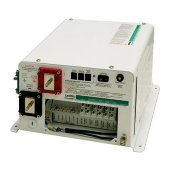
Features Transfer Switching Speed While this inverter is not designed as an uninterruptible power supply (UPS) system, its transfer time is normally fast enough to hold up most computers. The transfer time is typically 16 milliseconds. Front Panel Features Before installing and operating the RV Series Inverter/Charger, review the front panel features shown in Figure 1-1 and described in Table 1-2. -
Page 16: Accessories
RC/GS remote control. RC/GS RC/GS Remo te Control/G e n Starting Figure 1-2 Remote Control Panels The RC6, RC7, and RC/GS use a telephone-style cord to connect to the RV Series Inverter/Charger (models RV2012GS, RV2012GS-15/20B, RV2012GS-20B, RV2512GS, and RV3012GS). 1–4 975-0209-01-01... -
Page 17: Battery Temperature Sensor
Accessories Use only Xantrex-recommended accessories. Remote cables are available in three lengths: Part number Cable Length 31-6257-00 25 feet 31-6262-00 50 feet 31-6275-00 70 feet Battery Temperature Sensor The battery temperature sensor (BTS) allows the inverter/charger to monitor the battery temperature and adjust charging voltage according to the temperature. The BTS can extend the life of a battery by preventing overcharging in warm temperatures and undercharging in cold temperatures. - Page 18 1–6...
-
Page 19: Installation
Installation Chapter 2 contains information and procedures to install the RV Series Inverter/Charger. The topics in this chapter are organized as follows: • “Choosing a Location” • “Wiring the Inverter/Charger” • “Wiring to a Generator”... -
Page 20: Choosing A Location
Installation Choosing a Location Inverters are sophisticated electronic devices and should be treated accordingly. When selecting the operating environment for the inverter, don’t think of it in the same terms as other equipment that works with it, such as batteries, diesel generators, motor generators, washing machines, and so on. - Page 21 Choosing a Location Protected Never place the inverter/charger directly above the batteries—gases from battery from battery will corrode and damage the inverter/charger. If the acid and gases inverter/charger is installed in a compartment above the batteries, make sure there is a solid, gas-impermeable wall dividing the two compartments.
-
Page 22: Wiring The Inverter/Charger
Installation Wiring the Inverter/Charger WARNING: Fire, shock, and energy hazards Make sure all AC and DC wiring being connected to the RS is disconnected (physically or by opening the breaker) from all electrical sources before handling. All wiring must be done in accordance with local and national electrical wiring codes. -
Page 23: Ac Wiring
Wiring the Inverter/Charger RC/GS Remote RV Series Inverter/Charger DC + DC Load Center Grounding (Bonding) Bus DC Negative Grounding Bus DC Positive Bus DC - Engine Negative Terminal AC Out AC In DC Fuse AC Main Panel Engine Battery Battery Temperature Isolator Sensor House Battery... -
Page 24: Ac Input Wiring
Installation AC Input Wiring AC input to the inverter/charger can be supplied from a split-phase or dual-input AC source such as the utility grid (power company), a generator, or the output of a transfer switch. The inverter/charger can be operated from the following types of 120 volt 60 Hz AC sources: •... -
Page 25: General Precautions
Wiring the Inverter/Charger General Precautions AC disconnects No AC disconnects are provided as an integral part of this inverter. AC disconnects must be provided as part of the system installation. Over-current No over-current protection for the AC output wiring is provided as an integral part protection of this inverter. -
Page 26: Tools And Materials Required
Dual Input Model Input Wiring Output Wiring Input Wiring Output Wiring RV2012GS 10 AWG 10 AWG 6 AWG 6 AWG RV2012GS-15/20B 12 AWG 14*/12** AWG 8 AWG 14*/12** AWG RV2012GS-20B 12 AWG 12 AWG 8 AWG 12 AWG RV2512GS 10 AWG... -
Page 27: Connecting The Ac Wiring
Wiring the Inverter/Charger Connecting the AC Wiring AC connections are made on the terminal block located inside the front panel of the inverter. Figure 2-3 RV Series AC Wiring terminal block To connect AC wiring: 1. Disconnect the inverter from the battery. 2. -
Page 28: Dc Wiring
Installation DC Wiring Safety Instructions CAUTION: Equipment damage THIS INVERTER IS NOT REVERSE POLARITY PROTECTED. If the positive terminal of the battery is connected to the negative terminal of the inverter the probable result is failure of the whole power stage. This type of failure is not covered under warranty. -
Page 29: Connection Of Grounding And Battery Systems
Wiring the Inverter/Charger DC disconnects The DC circuit from the battery to the inverter/charger must be equipped with a disconnect and over-current protection device. (Refer to your applicable installation code.) Type This device usually consists of a circuit breaker, a “fused-disconnect,” or a separate fuse and DC disconnect. -
Page 30: Battery Cable Sizing
Table 2-2 Minimum Recommended Battery Cable Size (In Free Air) Individual Cable length Typical Maximum Model Amps Fuse Size Under 5 ft 5 to 10 ft RV2012GS 200 amps 250 A 0000 RV2512GS 250 amps 350 A 0000 0000 RV3012GS... -
Page 31: Battery Cable Connection
Wiring the Inverter/Charger WARNING: Fire hazard Use only appropriately sized copper cable. Loose connections or improper connections will overheat. Make sure the bolts supplied by Xantrex on the inverter/charger are tightened to a torque of 15–16 ft-lbs (20.4–21.7 Nm). Torque all other connections to the manufacturer’s specifications. - Page 32 Installation Figure 2-5 DC Cable Connection 5. Connect the connector at the other end of this cable to one of the terminals on the fuse or breaker. 6. Use a wrench to tighten the bolt to the torque recommended by the fuseholder or breaker manufacturer.
- Page 33 Wiring the Inverter/Charger Disconnecting battery cables CAUTION: Equipment damage Never disconnect the battery cables while the inverter is delivering power or the battery charger is operating. Disconnecting the battery cables could cause a rapid voltage increase that could damage the charger or other DC loads. Keep in mind that the Inverter switch on the inverter/charger does not turn off the charger section;...
-
Page 34: Connecting The Battery Temperature Sensor
Installation Connecting the Battery Temperature Sensor Installing a battery temperature sensor (BTS) extends the life of a battery by preventing overcharging in warm temperatures and undercharging in cold temperatures. With a BTS monitoring the battery temperature, the voltage delivered to the battery is adjusted according to the battery’s actual temperature. The BTS has a self-adhesive backing and attaches to the side of the battery. -
Page 35: Option B: Mounting To The Side Of The Battery Case
Connecting the Battery Temperature Sensor 5. Move or reorient the existing wiring ring terminals on the battery negative terminal stud, so there is a flat surface on which to seat the BTS mounting plate. You may need to bend the ring terminal crimp and/or wires slightly downward to allow the sensor to seat flush to the top surface of the upper ring terminal. -
Page 36: Wiring To A Generator
Installation 3. Clean the selected area thoroughly to remove any oil or grease that could prevent the sensor from adhering to the battery case. Allow the battery case to dry thoroughly. 4. Peel the backing from the self-adhesive strip on the rear of the sensor. Press the sensor firmly against the clean side of the battery to fix it in place, as shown in Figure 2-7. -
Page 37: Auto Gen Start Connections
Wiring to a Generator Auto Gen Start connections The connections between the inverter/charger and the generator are made on the terminal strip. All these components are located inside the AC compartment of the inverter. See Figure 2-8. Figure 2-8 RV Series Auto Gen Start terminal block Terminal Name Relay Description... - Page 38 Installation Relay This diagram shows the activity of each internal relay during a generator start sequence. timing Stop Relay1: Glow/Stop Preheat/ Stop Start Relay2: Start (Cranking) Crank Time Relay3: Preheat (Glow) Preheat Figure 2-9 Relay activity during a start sequence Table 2-3 Stop/Stop Sequence Timing Onan Power Tech...
-
Page 39: Generator Wiring Diagrams
Wiring to a Generator Generator Wiring Diagrams Onan Figure 2-10 Onan QuietDiesel Wiring Diagram Power Tech Figure 2-11 Power Tech Wiring Diagram 975-0209-01-01 2–21... -
Page 40: Wiring To A Thermostat
Installation Generac GEN RUN GEN RUN SIGNAL (B+) PREHEAT 2 GENERATOR BATTERY POSITIVE PREHEAT 1 PREHEAT COM. GEN START 1 GROUND N.O. GEN START 2 START N.C. GEN STOP 3 COM. GEN STOP 1 N.O. GEN STOP 2 GENERATOR WIRING HARNESS Figure 2-12 Generac Wiring Diagram Wiring to a Thermostat With the RC/GS remote control, you can enable the RV Series Inverter/Charger AGS to... -
Page 41: Operation
Operation Chapter 3 contains information about operating the RV Series Inverter/Charger. Topics in this chapter include: • “Remote Operation” on page 3–2 • “Stand-Alone Operation” on page 3–2 • “Search Mode” on page 3–2 • “Powering Loads” on page 3–3 •... -
Page 42: Remote Operation
Operation Remote Operation The RV Series Inverter/Charger is designed to operate stand alone or with a remote panel. The supported remote panels are the RC/GS, RC7, and RC6. The RC/GS enables advanced monitoring as well as configuration of the inverter/ charger and Automatic Generator Start feature. -
Page 43: Powering Loads
Powering Loads When in the search sense mode, the green power LED will blink and the inverter will make a ticking sound. At full output voltage, the green power LED will light steadily and the inverter will make a steady humming sound. When the inverter is used as an “uninterruptible”... -
Page 44: Inductive Loads
Operation Inductive Loads Any device that has a coil of wire in it probably has an inductive load characteristic. Most electronics have transformers (TVs, and stereos, for example) and are therefore inductive. Typically, the most inductive loads are motors. The most difficult load for the inverter to drive will be the largest motor you manage to start. - Page 45 Powering Loads load until line voltage is available. When this occurs, each unit waits for the other to begin. To drive these loads either a small companion load must be used to bring the inverter out of its search mode, or the inverter may be programmed to remain at full output voltage.
-
Page 46: Typical Battery Draw Of Common Appliances
Operation Typical Battery Draw of Common Appliances Amp Hours Consumed Over Time Appliance Watts 5 min 10 min 30 min 1 hr 2 hr 4 hr Single PL light Computer Color TV 13" Blender Skil Saw Toaster 1000 Microwave 1200 Hot Plate 1800 If the current draw at 120 Vac is known, then the battery amperage at 12 Vdc will... -
Page 47: Battery Charging
Battery Charging Battery Charging The RV Series Inverter/Charger battery charger uses three-stage charging to provide rapid and complete charge cycles without undue battery gassing. The three stages are bulk, absorption, and float. Stage One: Bulk Charge (Constant Current) This stage begins when qualified AC is applied to the AC input of the inverter. The bulk charging stage charges the batteries at a constant current. -
Page 48: Dead Battery Charging
Operation When batteries are cold, their chemical reaction is sluggish, and they do not absorb charge as easily. Therefore, a charge level optimized for room temperature will not charge the batteries sufficiently if they are cold. The charger must compensate by increasing its voltage to achieve the compensated equivalent of a room temperature charge. - Page 49 Battery Charging CAUTION: Batteries may be damaged Sealed lead-acid batteries and gel batteries must NEVER be equalized, or premature battery failure will result. Equalize mode is disabled if you have selected “GEL Cell” as the battery type. Only flooded lead-acid batteries should be equalized. As a general rule, do not equalize a battery unless there are provisions to add water to it and the manufacturer recommends equalization.
-
Page 50: Led Indicator
Operation LED Indicator Charger activity The RV Series Inverter/Charger has a three-color LED that indicates the activity of the battery charger. The optional RC/GS or RC7 remote allows custom control over the charger section of the inverter, including battery type. Table 3-1 LED color and Charger Activity LED color LED behavior... -
Page 51: Error Conditions
LED Indicator Error Conditions When an error condition occurs, the LED will flash red, followed by a five-second rest period. You can identify error conditions by counting the number of times the LED flashes before turning off for five seconds. The following table lists LED flashing patterns and their associated error conditions. - Page 52 3–12...
-
Page 53: Troubleshooting
Troubleshooting Chapter 4 contains information and procedures to troubleshoot the RV Series Inverter/Charger. -
Page 54: Troubleshooting Guide
Troubleshooting Troubleshooting Guide Symptoms Problem Remedy No power output and Battery voltage at the inverter’s Check the battery voltage, fuses or switches and no warning LEDs terminals is too low or not present. cable connections. No power output and Load is too small for search sense mode Reduce search threshold setting or defeat search LED indicator is circuit to detect. -
Page 55: A Specifications
Specifications Appendix A contains contains the electrical, environmental, and physical specifications for the RV Series Inverter/Charger. All specifications are subject to change without notice. -
Page 56: Electrical Specifications
Specifications Electrical Specifications RV2012GS RV2512GS RV3012GS Continuous Power @ 25°C 2000 watts 2500 watts 3000 watts Max AC Current 16.6 amps 20.8 amps 25 amps Efficiency 94% Peak Input Current: Search Mode 0.055 amps 0.070 amps 0.080 amps Input Current: Full Voltage 0.550 amps... -
Page 57: Physical Specifications
Physical Specifications Physical Specifications RV2012GS RV2512GS RV3012GS Weight 45 lb (20.5 kg) 50 lb (22.7 kg) 60 lb (27.2 kg) Dimensions (L × W × H) 15.5 × 13.2 × 7.25" (39.4 × 33.5 × 18.4 cm) Mounting Desktop, upside down, wall mount with AC terminal block facing up... - Page 58 A–4...
-
Page 59: Warranty And Return Information
Warranty What does this warranty cover? This Limited Warranty is provided by Xantrex Technology Inc. ("Xantrex") and covers defects in workmanship and materials in your RV Series Inverter/Charger. This warranty period lasts for 36 months from the date of purchase at the point of sale to you, the original end user customer. You require proof of purchase to make warranty claims. - Page 60 Warranty and Return What does this warranty not cover? This Limited Warranty does not cover normal wear and tear of the product or costs related to the removal, installation, or troubleshooting of the customer's electrical systems. This warranty does not apply to and Xantrex will not be responsible for any defect in or damage to: a) the product if it has been misused, neglected, improperly installed, physically damaged or altered, either inter- nally or externally, or damaged from improper use or use in an unsuitable environment;...
-
Page 61: Return Material Authorization Policy
Include the following: • The RMA number supplied by Xantrex Technology Inc. clearly marked on the outside of the box. • A return address where the unit can be shipped. Post office boxes are not acceptable. -
Page 62: Information About Your System
Warranty and Return Information About Your System As soon as you open your RV Series Inverter/Charger package, record the following information and be sure to keep your proof of purchase. Serial Number _________________________________ Purchased From _________________________________ Purchase Date _________________________________ If you need to contact Customer Service, please record the following details before calling. This information will help our representatives give you better service. - Page 64 Xantrex Technology Inc. 1 800 670 0707 Tel toll free NA 1 360 925 5097 Tel direct 1 360 925 5143 Fax direct customerservice@xantrex.com www.xantrex.com 975-0209-01-01 Printed in China...
Need help?
Do you have a question about the RV2012GS and is the answer not in the manual?
Questions and answers