
Related Manuals for Nu-Vu OP-2FM


Summary of Contents for Nu-Vu OP-2FM
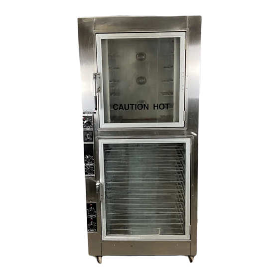
- Page 1 ® NU-VU Model: OP-2FM Manufactured for: A Quality Product Made in the U.S.A. Revised: 12 May 2003 ® NU–VU Food Service Systems P.O. Box 35 5600 13 STREET MENOMINEE, MICHIGAN 49858-0035 (800) 338-9886 FAX (906) 863-6322...
- Page 2 (This page is intentionally left blank)
- Page 3 (800) 338-9886. You can also FAX your question or comment to our Service Department at (906) 863-6322. You can even e-mail us at service@NU-VU.com. One of our service technicians will be glad to assist you. Please supply ®...
- Page 4 (This page is intentionally left blank)
-
Page 5: Table Of Contents
SUBWAY OP-2FM TABLE OF CONTENTS ABOUT YOUR OP-2FM ....................1 OP-2FM Specifications ..................2 RECEIPT, INSTALLATION AND START-UP Receipt ........................3 Installation ....................... 4 Electrical Connections ................... 4 Water Supply Connections ................5 Final Positioning ..................... 7 Start-Up Oven ......................... 8 Standard Proofer .................... - Page 6 (This page is intentionally left blank)
- Page 7 TABLE OF CONTENTS SERVICE AND REPLACEMENT GUIDE (cont.) Proofer Humidity Element, How to Replace ............... 29 Temperature Control, How to Adjust ................30 Temperature or Humidity Control, How to Replace Standard Controls ....................31 AUTOMIST Control ....................32 Oven Temperature Sensor, How to Replace ............. 32 Proofer Temperature or Humidity Sensor, How to Replace ........
- Page 8 (This page is intentionally left blank)
- Page 9 LIST OF ILLUSTRATIONS AND SCHEMATICS Figure #1 ..........Installation ............3 Figure #2 ......Power Supply Connections ........... 4 Figure #3 ........Phase Conversion ..........6 Figure #4 ..........Top Detail ............7 Figure #5 ........Proofer Controls ..........13 Figure #6 .........
- Page 10 (This page is intentionally left blank)
-
Page 11: About Your Op-2Fm
• Rapid servicing The OP-2FM is constructed of stainless steel inside and outside. All of the frame members are welded to provide lifetime durability, rigidity and long life construction. Components such as temperature and humidity controls, timers, switches, motors, heating elements, and others are thoroughly tested before shipment. -
Page 12: Op-2Fm Specifications
ABOUT YOUR OP–2FM OP–2FM OWNER'S MANUAL OP-2FM SPECIFICATIONS: Exterior Dimensions Height = 84" Width = 34 " Depth = 22 " Interior Dimensions (usable space) Oven Height = 26¼" Width = 19¼" Depth = 16 " Proofer Height = 33¾"... -
Page 13: Receipt, Installation And Start-Up Receipt
Check the Oven and Proofer Doors. Make sure both Doors close completely, and that the Door Gaskets seal firmly (refer to the DOOR TEST PROCEDURE in the SERVICE AND ® REPLACEMENT GUIDE). If they do not close or seal properly, please contact the NU-VU Service Department for instructions and assistance in any required adjustments. ®... -
Page 14: Installation
Check to determine that the power source is the same voltage and phase as that indicated on the label on ® the side of the unit. If the voltage and/or phase is not the same, please call NU-VU for instructions on changing the voltage and/or phase of your equipment. -
Page 15: Water Supply Connections
DO NOT change the phase of your equipment without first calling the NU-VU Service Department!!! If your OP-2FM is not equipped with the AUTOMIST option, you can now replace the Side Access Panel. Be careful not to pull or pinch any wires while installing the panel. If your OP-2FM is equipped with the AUTOMIST option, leave the Side Access Panel off until the water connection is completed. - Page 16 RECEIPT, INSTALLATION AND START-UP OP–2FM OWNER'S MANUAL Fig. #3 – PHASE CONVERSION NU–VU® FOOD SERVICE SYSTEMS PO BOX 35 MENOMINEE, MICHIGAN 49858-0035 page 6 SALES FAX (906) 863-5889 • SERVICE FAX (906) 863-6322 (800) 338-9886...
-
Page 17: Final Positioning
NOTE: The OP-2FM is constructed with a drain tube in the floor of the Proofer section. This drain tube prevents the build-up of any excess water, and helps to prevent damage to the Proofer Motor, Heating or Humidity Elements, or Control Sensors. -
Page 18: Start-Up
RECEIPT, INSTALLATION AND START-UP OP–2FM OWNER'S MANUAL START–UP: PRIOR TO ENERGIZING THE OP-2FM FOR THE FIRST TIME IT IS ADVISABLE TO SET ALL THE CONTROLS AND SWITCHES TO THEIR OFF POSITIONS. Oven - - A. Engage the main electrical and optional water supplies. -
Page 19: Automist Proofer
D. Check the thermometer reading against the Temperature Control setting when the Temperature Control Indicator Light goes out. If the readings differ by more than 10 the Temperature ® Control may need a simple adjustment. Please call the NU-VU Service Department BEFORE attempting calibration of the control. -
Page 20: Product Preparation And Use Of Unit
If you do not have ® a manual from your supplier you may obtain a manual of general information from NU-VU B. Study the manual and make up a list of questions. - Page 21 A. Set out the desired product for thawing (if necessary). Be sure to allow sufficient time in your production schedule for your Proofer to reach the correct operating conditions. NOTE: The OP-2FM is available with the AUTOMIST option in the Proofer. This option eliminates the manually-filled Water Pan in the Proofer by injecting and distributing a controlled water mist throughout the Proofer to provide proofing humidity.
- Page 22 PRODUCT PREPARATION AND USE OF UNIT OP–2FM OWNER'S MANUAL iv. In the AUTOMIST option is water being supplied to the Proofer? In the AUTOMIST option is the Injection Nozzle clogged or damaged? Recheck the proof in 5 to 10 minutes after making adjustments. Readjust as necessary.
-
Page 23: Operating Instructions
OP–2FM OWNER'S MANUAL OPERATING INSTRUCTIONS OPERATING INSTRUCTIONS PROOFER: The Proofer section should be pre-heated about 20 to 30 minutes before its intended use. Set the Proofer Temperature and Humidity Controls to the desired settings. If your Proofer is equipped with the AUTOMIST option, you can leave the Humidity Control OFF until you are actually ready to load thawed dough into the proofer. -
Page 24: Oven
Control setting. If water on the floor is a constant problem for you please call the ® NU-VU Service Department at (800) 338-9886. Load the Oven when your product is fully proofed. Yeast products should be 75% to 90% of the desired finished size at the end of the proof cycle. -
Page 25: General Settings
OP–2FM OWNER'S MANUAL OPERATING INSTRUCTIONS C. Close the Oven Door [41] securely. It is important that you keep the Oven Door closed unless actually loading or removing product. This helps to maintain Oven temperature, reduce baking time, and minimize energy usage. NOTE: It is helpful to slowly push the Oven Door closed until the Oven Motor restarts. -
Page 26: Baking Chart
OPERATING INSTRUCTIONS OP–2FM OWNER'S MANUAL NU–VU® FOOD SERVICE SYSTEMS PO BOX 35 MENOMINEE, MICHIGAN 49858-0035 page 16 SALES FAX (906) 863-5889 • SERVICE FAX (906) 863-6322 (800) 338-9886... -
Page 27: Maintenance And Cleaning Guide Maintenance
For example, both the Oven ® Motor and Proofer Motor have sealed bearings and never need to be lubricated. While NU-VU equipment is designed for minimum care and maintenance certain steps are required by the user for maximum life and effectiveness: •... -
Page 28: Cleaning
CLEANING: Your OP-2FM should be cleaned daily and as soon as possible after a spill has occurred. It is essential to maintain a clean unit, especially if the public views the unit in your place of business. The following should be used for cleaning: A. -
Page 29: Troubleshooting Guide
OP–2FM OWNER'S MANUAL TROUBLE–SHOOTING GUIDE TROUBLE–SHOOTING GUIDE OVEN: The Oven Power Switch [21] is in the ON position and there are no lights, heat, humidity or motor rotation: A. The Power Switch may be tripped. Set it all the way to OFF, then reset it to the ON position. B. - Page 30 TROUBLE–SHOOTING GUIDE OP–2FM OWNER'S MANUAL The Oven Door is open but the Oven Motor [7] continues to run: A. Check the Micro Switch [15] plunger in the top Oven Door Hinge [43]. The plunger must be free to move in and out. Eliminate any binding by adjusting the Switch (refer to MICRO SWITCH, How to Replace in the SERVICE AND REPLACEMENT GUIDE).
-
Page 31: Proofer
OP–2FM OWNER'S MANUAL TROUBLE–SHOOTING GUIDE VIII. The Buzzer Alarm [16] does not sound: A. Check the Oven Timer [24] for proper operation. B. Make sure the Buzzer Alarm wiring is correct. One side of the Buzzer Alarm is connected to terminal "6"... - Page 32 TROUBLE–SHOOTING GUIDE OP–2FM OWNER'S MANUAL III. The Proofer Power Switch [31] is in the ON position, you have lights, heat and Proofer Motor rotation but no humidity: For the standard manual-fill Proofer: A. Make sure the Water Pan [64] contains at least 2" of water. B.
- Page 33 OP–2FM OWNER'S MANUAL TROUBLE–SHOOTING GUIDE If the Fan Blade/Blower Wheel is not dragging on the Element Cover or the Proofer floor and the Proofer Motor spins easily by hand but still does not run: Check all electrical connections between the Power Switch and the Proofer Motor. All connections must be clean and tight.
-
Page 34: Service And Replacement Guide
OP–2FM OWNER'S MANUAL SERVICE AND REPLACEMENT GUIDE Your OP-2FM has been designed to be serviced quickly and easily. In fact, any individual who has average mechanical ability can do most of the work. Our Service Department is also available to you Monday through Friday from 7:00 a.m. - Page 35 OP–2FM OWNER'S MANUAL SERVICE AND REPLACEMENT GUIDE Fig. #7 – GENERAL EXPLODED VIEW NU–VU® FOOD SERVICE SYSTEMS PO BOX 35 MENOMINEE, MICHIGAN 49858-0035 (800) 338-9886 SALES FAX (906) 863-5889 • SERVICE FAX (906) 863-6322 page 25...
-
Page 36: Power Terminal Block And Contactor
IMPORTANT: IMPROPER INSTALLATION, MISUSE OR OTHER FAILURE TO FOLLOW THESE INSTRUCTIONS MAY CAUSE SEVERE EQUIPMENT DAMAGE ® OR PERSONAL INJURY, AND MAY ALSO VOID YOUR NU-VU WARRANTY!!! OVEN MOTOR ASSEMBLY, How To Replace: MAKE SURE ALL POWER TO THE UNIT IS OFF. FAILURE TO DO SO MAY CAUSE SEVERE EQUIPMENT DAMAGE OR PERSONAL INJURY! A. -
Page 37: Blower Wheel Installation And Balancing
OP–2FM OWNER'S MANUAL SERVICE AND REPLACEMENT GUIDE BLOWER WHEEL INSTALLATION AND BALANCING: When installing a new Blower Wheel it is imperative that the Wheel be balanced correctly. An improperly balanced Blower Wheel will cause premature failure of the Oven Motor. The Blower Wheel should rotate under power in a counter-clockwise direction when viewed from the open side of the Wheel (refer to Figure #8 on page 26). -
Page 38: Oven Heating Element, How To Replace
SERVICE AND REPLACEMENT GUIDE OP–2FM OWNER'S MANUAL Fig. #9 – PROOFER MOTORS Connect the electrical leads to the new Motor assembly. Make sure all connections are clean and tight. Lower the Motor assembly into place and fasten it securely with the four mounting screws. G. -
Page 39: Proofer Heating Element, How To Replace
OP–2FM OWNER'S MANUAL SERVICE AND REPLACEMENT GUIDE Route the Heating Element wires down the outside of the Oven and down to the contactor. Position the Heating Element wires where they will be out of the way and cut off any excess. Strip approximately ½"... -
Page 40: Temperature Control, How To Adjust
B. Compare the Temperature Control setting to the reading on the test instrument. If there is a ® difference of more than 25 in the Oven or 15 in the Proofer you should call the NU-VU Service Department for advice on adjusting or replacing components. -
Page 41: Temperature Or Humidity Control, How To Replace
OP–2FM OWNER'S MANUAL SERVICE AND REPLACEMENT GUIDE To increase the temperature inside the Oven or Proofer carefully rotate the index line on the clear dial clockwise. Each "click" of adjustment is equal to approximately 5 of temperature change in the Oven and 2 of temperature change in the Proofer. To decrease the inside temperature rotate the clear dial counter-clockwise. -
Page 42: Automist Control
SERVICE AND REPLACEMENT GUIDE OP–2FM OWNER'S MANUAL H. Attach all electrical wiring as labeled. Make sure all connections are clean and tight. IMPORTANT: THE RED LEAD FROM THE SENSOR CABLE MUST BE INSTALLED ON THE TC “-“ TERMINAL! Replace the Control Access Panel and secure it with the two mounting screws. Be careful not to pull or pinch any wires when replacing the panel. -
Page 43: Proofer Temperature Or Humidity Sensor, How To Replace
H. Replace the Side Access Panel. Be careful not to pull or pinch any wires when replacing the panel. ® NU-VU recommends that any replacement Control Sensor be tested for proper operation. It may be necessary to adjust the Temperature Control (refer to TEMPERATURE CONTROL, How To Adjust). -
Page 44: Timer, How To Replace
SERVICE AND REPLACEMENT GUIDE OP–2FM OWNER'S MANUAL Fig. #12 – 60-MINUTE TIMER TIMER, How To Replace: MAKE SURE ALL POWER TO THE UNIT IS OFF. FAILURE TO DO SO MAY CAUSE SEVERE EQUIPMENT DAMAGE OR PERSONAL INJURY! A. Remove the Knob of the defective Timer by pulling it straight out from the face of the Control Access Panel. -
Page 45: Power Switch, How To Replace
OP–2FM OWNER'S MANUAL SERVICE AND REPLACEMENT GUIDE C. Label and disconnect the Buzzer wiring, OR disconnect the wires one at a time and transfer them to the same location on the replacement Buzzer. One terminal should lead back to "4" on back of a Timer [24 or 36]. -
Page 46: Indicator Light, How To Replace
SERVICE AND REPLACEMENT GUIDE OP–2FM OWNER'S MANUAL C. Disconnect the wires one at a time and install them on the new Micro Switch. Make sure all connections are clean and tight. D. Turn one mounting nut onto the Micro Switch until it is approximately half-way down the threaded shaft. -
Page 47: Solenoid Valve, How To Replace
OP–2FM OWNER'S MANUAL SERVICE AND REPLACEMENT GUIDE Fig. #15 – AUTOMIST COMPONENTS D. Insert the mounting screw through the center of the replacement Repeat Cycle Timer and fasten the Timer to the mounting bracket. Do not overtighten the mounting screw or you may crack the Timer's plastic case. -
Page 48: Door Latch, How To Adjust
SERVICE AND REPLACEMENT GUIDE OP–2FM OWNER'S MANUAL G. Position the plumbing connections on the Solenoid Valve body and snug them in place, but do not over-tighten the fitting! If any joint leaks when tested and further gentle tightening does not stop the leak the entire fitting must be replaced. -
Page 49: Door Latch, How To Replace
Hinges on Flush-Mount Doors are preset at the NU-VU factory and should not need adjustment. ® However, if you experience any problems with Door operation please call the NU-VU Service Department for assistance at (800) 338-9886. HINGES, How To Replace: A. -
Page 50: Door Gasket, How To Replace
DOOR GASKET, How To Replace: Follow these instructions to correctly install your Door Gasket with minimal problems. Use the ® installation kit provided. If you have any problems or questions call NU-VU at (800) 338–9886 and ask for the Service Department. -
Page 51: Caster, How To Replace
OP–2FM OWNER'S MANUAL SERVICE AND REPLACEMENT GUIDE IMPORTANT: DO NOT STRETCH OR PULL ON THE GASKET DURING INSTALLATION. THIS WILL LATER CAUSE THE TRIMMED CORNERS TO SEPARATE AND PULL APART! Use a sharp knife or a single-edged razor blade to cut the ends of the Gasket at a 45 angle (you can use the mitered corner joint on the Door as an angle guide). -
Page 52: To Lay Unit Down
SERVICE AND REPLACEMENT GUIDE OP–2FM OWNER'S MANUAL C. With a small jack, or using the lever and fulcrum method (such as a length of board and a small wooden block), gently lift the affected side of the unit until the Caster is clear of the floor (1" is sufficient). -
Page 53: Nu-Vu® Equipment Warranty
The return of defective parts is required. The return of a defective part or component must be made prior ® to the issuance of a credit on an open account. If a part that is returned tests satisfactory in the NU-VU ®... -
Page 54: Warranty Limitations
Recalibration of temperature and humidity controls (all controls are carefully calibrated and tested at our facility before shipment). ® Any equipment moved from the place of original installation unless NU-VU agrees in writing to continue the warranty after the relocation. -
Page 55: Parts Return Procedure And Conditions
OP–2FM OWNER'S MANUAL NU–VU® EQUIPMENT WARRANTY ® Products must be installed and maintained in accordance with NU-VU instructions. Users are responsible for the suitability of the products to their application. There is no warranty against damage resulting from accident, abuse, alteration, misapplication, inadequate storage prior to installation, or improper specification or other operating conditions beyond our immediate control. -
Page 56: Replacement Parts List
Please supply the Serial Number, Model Number and Manufacture Date Code from ® the side-mounted nameplate of your NU-VU Oven/Proofer when ordering ® replacement parts or requesting service for your NU-VU equipment. NU–VU® FOOD SERVICE SYSTEMS PO BOX 35 MENOMINEE, MICHIGAN 49858-0035 page 46 SALES FAX (906) 863-5889 •... -
Page 57: Oven Control Components
Please supply the Serial Number, Model Number and Manufacture Date Code from ® the side-mounted nameplate of your NU-VU Oven/Proofer when ordering ® replacement parts or requesting service for your NU-VU equipment. NU–VU® FOOD SERVICE SYSTEMS PO BOX 35 MENOMINEE, MICHIGAN 49858-0035 (800) 338-9886 SALES FAX (906) 863-5889 •... -
Page 58: Oven Interior Components
Please supply the Serial Number, Model Number and Manufacture Date Code from ® the side-mounted nameplate of your NU-VU Oven/Proofer when ordering ® replacement parts or requesting service for your NU-VU equipment. NU–VU® FOOD SERVICE SYSTEMS PO BOX 35 MENOMINEE, MICHIGAN 49858-0035 page 48 SALES FAX (906) 863-5889 •... - Page 59 N U - V U F o o d S e r v i c e S y s t e m s...
- Page 60 N U - V U F o o d S e r v i c e S y s t e m s...
- Page 61 N U - V U F o o d S e r v i c e S y s t e m s...
- Page 62 N U - V U F o o d S e r v i c e S y s t e m s...
Need help?
Do you have a question about the OP-2FM and is the answer not in the manual?
Questions and answers