Table of Contents
Advertisement
Quick Links
Download this manual
See also:
User Manual
Advertisement
Table of Contents

Subscribe to Our Youtube Channel
Related Manuals for Supermicro X9DRW-3F


Summary of Contents for Supermicro X9DRW-3F
- Page 1 Инструкция для SuperMicro X9DRW-3F Перейти в карточку товара 8 800 775 98 98...
- Page 2 X9DRW-3F X9DRW-iF USER’S MANUAL Revision 1.0...
- Page 3 This product, including software and docu- mentation, is the property of Supermicro and/or its licensors, and is supplied only under a license. Any use or reproduction of this product is not allowed, except as expressly permitted by the terms of said license.
-
Page 4: About This Motherboard
The Super X9DRW-3F/X9DRW-iF motherboard supports dual Intel E5-2600 Series (Socket R) processors and Intel QPI (QuickPath Interface) Technology (V.1.1), providing point-to-point connections with transfer speeds of up to 8.0 TG/s. With the Intel PCH C606/C602 chipset built in, the X9DRW-3F/X9DRW-iF motherboard supports Intel ®... -
Page 5: Conventions Used In The Manual
X9DRW-3F/X9DRW-iF Motherboard User’s Manual Conventions Used in the Manual Pay special attention to the following symbols to install your system properly and to prevent damage to your system or injury to yourself: Danger/Caution: Instructions to be strictly followed to prevent catastrophic... -
Page 6: Contacting Supermicro
Super Micro Computer, Inc. 980 Rock Ave. San Jose, CA 95131 U.S.A. Tel: +1 (408) 503-8000 Fax: +1 (408) 503-8008 Email: marketing@supermicro.com (General Information) support@supermicro.com (Technical Support) Website: www.supermicro.com Europe Address: Super Micro Computer B.V. Het Sterrenbeeld 28, 5215 ML... -
Page 7: Table Of Contents
X9DRW-3F/X9DRW-iF Motherboard User’s Manual Table of Contents Preface Chapter 1 Overview Overview ......................1-1 Processor and Chipset Overview..............1-11 Special Features ................... 1-12 PC Health Monitoring ..................1-12 ACPI Features ....................1-13 Power Supply ....................1-13 Super I/O ....................... 1-14 Advanced Power Management ..............1-14 Introduction to the IPMI Controller ............... - Page 8 Table of Contents NMI Button ....................2-19 Power LED ....................2-19 HDD LED ....................2-20 NIC1/NIC2 LED Indicators ............... 2-20 Overheat (OH)/Fan Fail/PWR Fail/UID LED ..........2-21 Power Fail LED ..................2-21 Reset Button ................... 2-22 Power Button ................... 2-22 Connecting Cables ..................
- Page 9 X9DRW-3F/X9DRW-iF Motherboard User’s Manual No Power ......................3-1 No Video ......................3-2 System Boot Failure ..................3-2 ............3-2 Memory Errors ....................3-3 When the System Becomes Unstable ............3-3 Technical Support Procedures ................ 3-5 Battery Removal and Installation ..............3-6 Battery Removal ....................
-
Page 10: Chapter 1 Overview
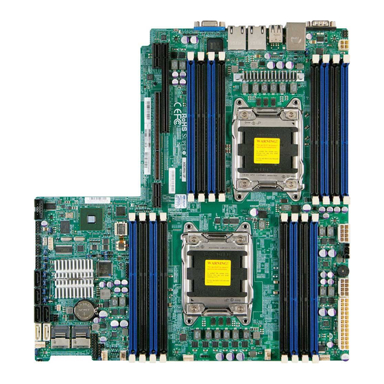
Checklist Congratulations on purchasing your computer motherboard from an acknowledged leader in the industry. Supermicro boards are designed with the utmost attention to detail to provide you with the highest standards in quality and performance. Please check that the following items have all been included with your motherboard. - Page 11 X9DRW-3F/X9DRW-iF Motherboard User’s Manual Motherboard Image Note: All graphics shown in this manual were based upon the latest PCB Revision available at the time of publishing of the manual. The motherboard you've received may or may not look exactly the same as the graphics...
-
Page 12: Motherboard Layout
Chapter 1: Overview Motherboard Layout COM1 USB0/1 JUIDB CTRL LAN1 LAN2 USB2/3 JPW4 IPMI-LAN CPU2 COM2 X9DRW-3F/iF Rev.1.02 CTRL JPW3 JI2C1 JVRM_I2C1 JPG1 BIOS JVRM_I2C2 CPU1 JPW2 JBT1 JBAT1 SATA/ SCU0~3 SATA/SCU4~7 JSM1 JSM2 JVR1 FAN1 FAN3 Notes: See Chapter 3 for detailed information on jumpers, I/O ports and JF1 front panel connections. -
Page 13: Default Setting
X9DRW-3F/X9DRW-iF Motherboard User’s Manual X9DRW-3F/X9DRW-iF Quick Reference LED3 LAN2 LAN1 USB 0/1 COM1 USB 2/3 COM1 USB0/1 JUIDB LAN CTLR JPL1 CTRL LAN1 LAN2 USB2/3 IPMI-LAN JPW4 IPMI LAN CPU2 CPU2 LED1 JSTBY1 BMC CTLR COM2 X9DRW-3F/iF Rev.1.02 CTRL JPW3... - Page 14 Chapter 1: Overview X9DRW-3F/X9DRW-iF Connectors Connectors Description COM1/COM2 Backplane COM Port1/Front Accessible COM2 Header FAN1~4,FANA, FANB CPU/System Fan Headers I-SATA 0~5 Intel PCH SATA Connectors 0~5 JBAT1 Onboard Battery (See Chpt. 4 for Used Battery Disposal) Speaker/Power LED Connector (Pins 1~3: PWR LED, Pins...
- Page 15 X9DRW-3F/X9DRW-iF Motherboard User’s Manual VGA1 Backpanel VGA Port 1/Front Panel VGA Port2 X9DRW-3F/X9DRW-iF LED Indicators Description State Status LED1 Green: Blinking Normal LED2 Power LED Green: On SB Power On LED3 UID LED Blue: On Warning! To prevent damage to the power supply or motherboard, please use a power supply that contains a 24-pin, two 8-pin power connectors and one 4-pin power connector.
-
Page 16: Motherboard Features
Chapter 1: Overview Motherboard Features Dual Intel ® E5-2600 series (Socket R of up to 130W) processors; each processor supports two full-width Intel QuickPath Interconnect (QPI) links of up to 8.0 GT/s per QPI link and with data transfer rate of up to 16 GB/s direction peak bandwidth per port Memory 1. - Page 17 X9DRW-3F/X9DRW-iF Motherboard User’s Manual SAS/SATA/SCU Connection Eight (8) Connections 0~3, 4~7 (For X9DRW-3F), Four (4) Connections 0~3 (For X9DRW-iF) RAID 0, 1, 10 IPMI 2.0 IPMI 2.0 supported by the Renesas BMC Serial (COM) Port Two (2) Fast UART 16550 connections: 9-pin RS-...
- Page 18 Chapter 1: Overview Fan Control Width Modulation) fan speed control Low noise fan speed control LED Indicators System/CPU Overheat LED Suspend-state LED System Management UID/Remote UID LED System Management 2.0 support System resource alert via SuperDoctor III Dual Cooling Zones Thermal Monitor 2 (TM2) support support SuperDoctor III, Watch Dog, NMI...
- Page 19 X9DRW-3F/X9DRW-iF Motherboard User’s Manual Right Slot PCIE 3.0x16 PE2 PE1 CPU Rear Socket 01 PROCESSOR CPU Front Socket 00 PROCESSOR BIOS P0PE3 SPI Flash Lane Reversal & Polarity Inversion DMI: Lane Reversal Left Slot PCIE 3.0x16+x16 SATA [0...5] PEG [0...3]...
-
Page 20: Processor And Chipset Overview
WIO platforms. With support of Intel QuickPath interconnect (QPI) Technology, the X9DRW-3F/ X9DRW-iF motherboard offers point-to-point serial interconnect interface with a transfer speed of up to 8.0 GT/s, providing superb system performance. -
Page 21: Special Features
X9DRW-3F/X9DRW-iF Motherboard User’s Manual Special Features Recovery from AC Power Loss The Basic I/O System (BIOS) provides a setting that determines how the system will respond when AC power is lost and then restored to the system. You can choose for the system to remain powered off (in which case you must press the power switch to turn it back on), or for it to automatically return to the power-on state. -
Page 22: Acpi Features
It is even more important for processors that have high CPU clock rates. The X9DRW-3F/X9DRW-iF motherboard accommodates 24-pin ATX power sup- by the CPU, some are inadequate. In addition, two 12V 8-pin power connections (JPW2/JPW3) and a 4-pin power connector are also required to ensure adequate power supply to the system. -
Page 23: Super I/O
X9DRW-3F/X9DRW-iF Motherboard User’s Manual It is strongly recommended that you use a high quality power supply that meets ATX information, please refer to the website at http://www.ssiforum.org/). Additionally, in areas where noisy power transmission is present, you may choose to install a line power surge protector to help avoid problems caused by power surges. -
Page 24: Bmc Subsystem Features
Chapter 1: Overview Controller offers the user a superb solution to manage PC server systems with The BMC controller supports a 32Kb_instruction cache and a 32Kb_operand cache, which can be switched between write-back and write-through. The instruction cache offers a 4-way full-associative instruction TBL (Translation Lookaside Buffer) and a 64-way full-associative shared TBL. - Page 25 X9DRW-3F/X9DRW-iF Motherboard User’s Manual Notes 1-16...
-
Page 26: Chapter 2 Installation
Chapter 2: Installation Chapter 2 Installation Static-Sensitive Devices Electrostatic Discharge (ESD) can damage electronic com ponents. To avoid dam- aging your system board, it is important to handle it very carefully. The following Precautions Use a grounded wrist strap designed to prevent static discharge. Touch a grounded metal object before removing the board from the antistatic bag. -
Page 27: Processor And Heatsink Installation
CPU socket cap is in place and none of the socket pins are bent; otherwise, contact your retailer immediately. Refer to the Supermicro website for updates on CPU support. Installing the LGA2011 Processor 1. There are two load levers on the LGA2011 socket. To open the socket cover,... - Page 28 Chapter 2: Installation 1. Press the second load lever labeled 'Close 1st' to release the load plate that covers the CPU socket from its locking position. Pull lever away from Press down on Load the socket Lever 'Close 1st' 2. With the lever labled 'Close 1st' fully retracted, gently push down on the 'Open 1st' lever to open the load plate.
- Page 29 X9DRW-3F/X9DRW-iF Motherboard User’s Manual from the socket. keys, which are semi-circle cutouts, against the socket keys. Socket Keys CPU Keys 3. Once they are aligned, carefully lower the CPU straight down into the socket. (Do not drop the CPU on the socket. Do not move the CPU horizontally or vertically.
- Page 30 Chapter 2: Installation 1. With the CPU inside the socket, inspect the four corners of the CPU to make sure that the CPU is properly installed. 2. Close the load plate with the CPU inside the socket. Lock the lever labeled gently push the load levers down to the lever locks.
-
Page 31: Installing A Passive Cpu Heatsink
X9DRW-3F/X9DRW-iF Motherboard User’s Manual Installing a Passive CPU Heatsink 1. Apply the proper amount of thermal grease (with thickness of up to 0.13 mm) to the heatsink. 2. Place the heatsink on top of the CPU so that the two mounting holes on the heatsink are aligned with those on the retention mechanism. -
Page 32: Installing And Removing The Memory Modules
Installing and Removing the Memory Modules Note: Check Supermicro's Website for recommended memory modules. CAUTION Exercise extreme care when installing or removing DIMM modules to prevent any possible damage. -
Page 33: Removing Memory Modules
X9DRW-3F/X9DRW-iF Motherboard User’s Manual 6. Press the release tabs to the locked positions to secure the DIMM module into the slot. Press both notches straight down into the memory slot at the same time. Notes: 1. For proper memory installation, be sure to install a DIMM module into the P2-DIMMG1 slot before inserting a 4-pin power connector into JPW4 as shown in the graphics below. - Page 34 It also supports 512 GB (max.) of LRDIMM (Reduced Load) DDR3 800/1066/1333/ MHz memory modules. For the latest memory updates, please refer to our Website a at http://www.supermicro.com/products/motherboard. For system memory to work properly, follow the tables below for memory instal- lation.
- Page 35 X9DRW-3F/X9DRW-iF Motherboard User’s Manual RDIMM Support on the Intel E5-2600 Series Processor Platform DIMMs Populated per RDIMM Type POR Speeds (in Ranks per DIMM DDR Channel (Reg. DIMM) MHz) (Any Combination) Reg. ECC DDR3 1066, 1333, 1600 SR, DR Reg. ECC DDR3...
-
Page 36: Motherboard Installation
Standoffs (7 pieces, if needed) Location of Mounting Holes There are seven (7) mounting holes on this motherboard indicated by the arrows. X9DRW-3F/iF Rev. 1.02 Caution: 1) To avoid damaging the motherboard and its components, please do not use a force greater than 8 lb/inch on each mounting screw during motherboard installation. -
Page 37: Installing The Motherboard
X9DRW-3F/X9DRW-iF Motherboard User’s Manual Installing the Motherboard 1. Install the I/O shield into the chassis. 2. Locate the mounting holes on the motherboard. 3. Locate the matching mounting holes on the chassis. Align the mounting holes on the motherboard with the mounting holes on the chassis. -
Page 38: Control Panel Connectors And I/O Ports
Chapter 2: Installation Control Panel Connectors and I/O Ports the picture below for the colors and locations of the various I/O ports. Back Panel Connectors and I/O Ports X9DRW-3F/iF Rev. 1.02 1. COM Port 1 (Turquoise) 2. Back Panel USB Port 0 3. -
Page 39: Universal Serial Bus (Usb)
X9DRW-3F/X9DRW-iF Motherboard User’s Manual Universal Serial Bus (USB) FP USB (4/5) Backplane USB (USB 0/1, 2/3) Four Universal Serial Bus ports (USB USB 4 USB 5 0/1, 2/3) are located on the I/O back panel. In addition, one USB header,... -
Page 40: Serial Ports
Ground COM2 Video Connection One video (VGA) port (VGA1) is lo- cated next to LAN Port 2 on the I/O backplane. Refer to the board layout below for the location. 1. COM1 2. COM2 3. VGA1 X9DRW-3F/iF Rev. 1.02 2-15... -
Page 41: Ethernet Ports
X9DRW-3F/X9DRW-iF Motherboard User’s Manual Ethernet Ports LAN Ports Two Gigabit Ethernet ports (LAN1/2) are located on the I/O backplane on P2V5SB SGND the motherboard to provide internet TD0+ Act LED connections. In addition, an IPMI_ TD0- P3V3SB Dedicated LAN, located above USB... - Page 42 3.3V tion on IPMI, please refer Reset Reset Button Ground to the IPMI User's Guide Power Button Ground posted on our Website @ http://www.supermicro.com. 1. UID Switch 2. Rear UID LED (LED3) 3. Front UID LED X9DRW-3F/iF Rev. 1.02 2-17...
-
Page 43: Front Control Panel
X9DRW-3F/X9DRW-iF Motherboard User’s Manual Front Control Panel JF1 contains header pins for various buttons and indicators that are normally lo- cated on a control panel at the front of the chassis. These connectors are designed descriptions of the various control panel buttons and LED indicators. Refer to the... -
Page 44: Nmi Button
IPMI-LAN JPW4 Ground FP PWRLED 3.3 V CPU2 HDD LED ID_UID_SW/3/3V Stby NIC1 Link LED NIC1 Activity LED COM2 X9DRW-3F/iF Rev.1.02 CTRL NIC2 Activity LED JPW3 NIC2 Link LED Blue+ (OH/Fan Fail/ JI2C1 JVRM_I2C1 JPG1 Red+ (Blue LED Cathode) BIOS... -
Page 45: Hdd Led
X9DRW-3F/X9DRW-iF Motherboard User’s Manual HDD LED HDD LED The HDD LED connection is located on pins 13 and 14 of JF1. Attach a 3.3V Standby cable here to indicate HDD activ- HD Active ity. See the table on the right for pin... -
Page 46: Overheat (Oh)/Fan Fail/Pwr Fail/Uid Led
JPW4 IPMI-LAN FP PWRLED 3.3 V HDD LED ID_UID_SW/3/3V Stby CPU2 NIC1 Link LED NIC1 Activity LED COM2 X9DRW-3F/iF NIC2 Activity LED NIC2 Link LED Rev.1.02 CTRL JPW3 Blue+ (OH/Fan Fail/ Red+ (Blue LED Cathode) JI2C1 JVRM_I2C1 PWR FaiL/UID LED) -
Page 47: Reset Button
X9DRW-3F/X9DRW-iF Motherboard User’s Manual Reset Button Reset Button The Reset Button connection is located on pins 3 and 4 of JF1. Attach it to a Reset hardware reset switch on the computer Ground case. Refer to the table on the right for... -
Page 48: Connecting Cables
CTRL LAN1 LAN2 USB2/3 IPMI-LAN JPW4 B. JPW2: 8-pin Processor PWR (Req'd) C. JPW3: 8-pin Processor PWR, or D. JPW4: 4-pin PWR (re- quired) CPU2 COM2 X9DRW-3F/iF Rev.1.02 CTRL JPW3 JI2C1 JVRM_I2C1 JPG1 BIOS JVRM_I2C2 CPU1 JPW2 JBT1 JBAT1 SCU0~3... -
Page 49: Fan Headers
X9DRW-3F/X9DRW-iF Motherboard User’s Manual Fan Headers Fan Header This motherboard has six system/CPU fan headers (Fan 1~Fan 4, Fan A, Fan Ground B) on the motherboard. All these 4-pin +12V fans headers are backward compatible Tachometer with the traditional 3-pin fans. However,... -
Page 50: Internal Speaker
Refer to the tables on right for COM1 A. Internal Speaker (Buzz- USB0/1 JUIDB CTRL LAN1 LAN2 USB2/3 IPMI-LAN JPW4 B. OH LED CPU2 COM2 X9DRW-3F/iF Rev.1.02 CTRL JPW3 JI2C1 JVRM_I2C1 JPG1 BIOS JVRM_I2C2 CPU1 JPW2 JBT1 JBAT1 SCU0~3... -
Page 51: Port 80 Header
X9DRW-3F/X9DRW-iF Motherboard User’s Manual Port 80 Header Port 80 Header A Port 80 header, located at JLPC1, provides Port 80 support. Port 80 is +3.3V an "Ask and Respond" port between LFRAME# a client machine and a host server. LCLK... -
Page 52: Power Smb (I C) Connector
C connection on Clock your system. No Connection A. JPI COM1 USB0/1 JUIDB B. IPMB CTRL LAN1 LAN2 USB2/3 JPW4 IPMI-LAN CPU2 COM2 X9DRW-3F/iF Rev.1.02 CTRL JPW3 JI2C1 JVRM_I2C1 JPG1 BIOS JVRM_I2C2 CPU1 JPW2 JBT1 JBAT1 SATA/ SCU0~3 SATA/SCU4~7 JSM1... -
Page 53: T-Sgpio 1/2 Headers
X9DRW-3F/X9DRW-iF Motherboard User’s Manual T-SGPIO 1/2 Headers T-SGPIO Two SGPIO (Serial-Link General Purpose Input/Output) headers are located on the motherboard. These Ground Data headers support Serial_Link interface Load Ground for onboard SATA connections. See Clock Note: NC= No Connection tions. -
Page 54: Power Led/Speaker
External Speaker 6-7 with a jumper. Pins 6-7 Internal Speaker A. PWR LED/Speaker COM1 USB0/1 JUIDB CTRL LAN1 LAN2 USB2/3 JPW4 IPMI-LAN CPU2 COM2 X9DRW-3F/iF Rev.1.02 CTRL JPW3 JI2C1 JVRM_I2C1 JPG1 BIOS JVRM_I2C2 CPU1 JPW2 JBT1 JBAT1 SATA/ SCU0~3 SATA/SCU4~7... -
Page 55: Jumper Settings
X9DRW-3F/X9DRW-iF Motherboard User’s Manual Jumper Settings Explanation of Jumpers Connector Pins To modify the operation of the mother- board, jumpers can be used to choose between optional settings. Jumpers cre- Jumper ate shorts between two pins to change the function of the connector. Pin 1 Setting on the printed circuit board. -
Page 56: Cmos Clear
Watch Dog must also be enabled in the BIOS. A. Clear CMOS COM1 USB0/1 JUIDB B. Watch Dog Enable CTRL LAN1 LAN2 USB2/3 JPW4 IPMI-LAN CPU2 COM2 X9DRW-3F/iF Rev.1.02 CTRL JPW3 JI2C1 JVRM_I2C1 JPG1 BIOS JVRM_I2C2 CPU1 JPW2 JBT1 JBAT1 SATA/ SCU0~3... -
Page 57: Vga Enable
X9DRW-3F/X9DRW-iF Motherboard User’s Manual VGA Enable VGA Enable Jumper Settings Jumper JPG1 allows the user to enable the onboard VGA connector. The default Enabled (Default) setting is 1-2 to enable the connection. Disabled See the table on the right for jumper settings. - Page 58 See the table on the right for jumper settings. A. JI COM1 USB0/1 JUIDB B. JI CTRL LAN1 LAN2 USB2/3 JPW4 IPMI-LAN CPU2 COM2 X9DRW-3F/iF Rev.1.02 CTRL JPW3 JI2C1 JVRM_I2C1 JPG1 BIOS JVRM_I2C2 CPU1 JPW2 JBT1 JBAT1 SATA/ SCU0~3...
-
Page 59: Onboard Led Indicators
X9DRW-3F/X9DRW-iF Motherboard User’s Manual Onboard LED Indicators Activity LED Link LED GLAN LEDs The LAN 1/2 ports are located on the IO Rear View (when facing the rear side of the chassis) Backplane. Each Ethernet LAN port has GLAN Activity Indicator (Right) two LEDs. -
Page 60: Onboard Power Led
Refer to UID Switch on Page 2-17 for more information. A. PWR LED COM1 USB0/1 JUIDB B. Rear UID LED CTRL LAN1 LAN2 USB2/3 JPW4 IPMI-LAN CPU2 COM2 X9DRW-3F/iF Rev.1.02 CTRL JPW3 JI2C1 JVRM_I2C1 JPG1 BIOS JVRM_I2C2 CPU1 JPW2 JBT1 JBAT1 SATA/ SCU0~3... -
Page 61: Bmc Heartbeat Led
X9DRW-3F/X9DRW-iF Motherboard User’s Manual BMC Heartbeat LED BMC Heartbeat LED Status A BMC Heartbeat LED is located at LED1 on the motherboard. When LED1 is blink- Green: BMC: Normal ing, BMC functions normally. See the Blinking table at right for more information. -
Page 62: Sata/Scu Connections
Ground cluding four SATA2 ports and two SATA3 TX_P ports. There are also eight SCU ports TX_N (0~3, 4~7) located on the X9DRW-3F, and Ground four SCU ports (SCU 0~3) located on the RX_N X9DRW-iF. These ports provide serial-link RX_P... - Page 63 X9DRW-3F/X9DRW-iF Motherboard User’s Manual Notes 2-38...
-
Page 64: Chapter 3 Troubleshooting
Chapter 3: Troubleshooting Chapter 3 Troubleshooting Troubleshooting Procedures Use the following procedures to troubleshoot your system. If you have followed all of the procedures below and still need assistance, refer to the ‘Technical Support Procedures’ and/or ‘Returning Merchandise for Service’ section(s) in this chapter. Always disconnect the AC power cord before adding, changing or installing any hardware components. -
Page 65: No Video
X9DRW-3F/X9DRW-iF Motherboard User’s Manual No Video 1. If the power is on, but you have no video, remove all the add-on cards and cables. 2. Use the speaker to determine if any beep codes exist. Refer to Appendix A for details on beep codes. -
Page 66: Memory Errors
2. Memory support: Make sure that the memory modules are supported by test- ing the modules using memtest86 or a similar utility. Note: Refer to the product page on our website http:\\www.supermicro. com for memory and CPU support and updates. - Page 67 X9DRW-3F/X9DRW-iF Motherboard User’s Manual within the normal range. Also check the front panel Overheat LED, and make sure that the Overheat LED is not on. 5. Adequate power supply: Make sure that the power supply provides adequate power to the system. Make sure that all power connectors are connected.
-
Page 68: Technical Support Procedures
Technical Support Procedures Before contacting Technical Support, please make sure that you have followed all the steps listed below. Also, Note that as a motherboard manufacturer, Supermicro reseller for troubleshooting services. They should know of any possible problem(s) 1. Please go through the ‘Troubleshooting Procedures’ and 'Frequently Asked Question' (FAQ) sections in this chapter or see the FAQs on our website (http://www.supermicro.com/) before contacting Technical Support. -
Page 69: Battery Removal And Installation
X9DRW-3F/X9DRW-iF Motherboard User’s Manual Battery Removal and Installation Battery Removal To remove the onboard battery, follow the steps below: 1. Power off your system and unplug your power cable. 2. Locate the onboard battery as shown below. 3. Using a tool such as a pen or a small screwdriver, push the battery lock out- wards to unlock it. -
Page 70: Frequently Asked Questions
Note : The SPI BIOS chip used on this motherboard cannot be removed. Send your motherboard back to our RMA Department at Supermicro for repair. For BIOS Recovery instructions, please refer to the AMI BIOS Recovery Instructions posted at http://www.supermicro.com. -
Page 71: Returning Merchandise For Service
X9DRW-3F/X9DRW-iF Motherboard User’s Manual Question: What's on the CD that came with my motherboard? Answer: The supplied compact disc has quite a few drivers and programs that will greatly enhance your system. We recommend that you review the CD and install the applications you need. -
Page 72: Chapter 4 Bios
BIOS Introduction This chapter describes the AMI BIOS Setup utility for the X9DRW-3F/X9DRW-iF. It also provides the instructions on how to navigate the AMI BIOS Setup utility screens. The AMI ROM BIOS is stored in a Flash EEPROM and can be easily updated. -
Page 73: Main Setup
X9DRW-3F/X9DRW-iF Motherboard User’s Manual Warning! Do not upgrade the BIOS unless your system has a BIOS-related issue. Flashing the wrong BIOS can cause irreparable damage to the sys- tem. In no event shall the manufacturer be liable for direct, indirect, special, incidental, or consequential damage arising from a BIOS update. -
Page 74: Boot Features
Chapter 4: AMI BIOS Memory Information Total Memory This displays the amount of memory that is available in the system. Use the arrow keys to select Advanced Setup and press <Enter> to access the following submenu items. Boot Features Quiet Boot This feature allows the user to select bootup screen display between POST mes- sages and the OEM logo. - Page 75 X9DRW-3F/X9DRW-iF Motherboard User’s Manual Wait For 'F1' If Error Select Enabled to force the system to wait until the 'F1' key is pressed if an error occurs. The options are Disabled and Enabled. Interrupt 19 Capture Interrupt 19 is the software interrupt that handles the boot disk function. When this item is set to Enabled, the ROM BIOS of the host adaptors will "capture"...
- Page 76 Chapter 4: AMI BIOS Type of CPU CPU Signature Microcode Patch CPU Stepping Maximum CPU Speed Minimum CPU Speed Processor Cores Intel HT (Hyper-Threading) Technology Intel VT-x Technology Intel SMX Technology L1 Data Cache L1 Code Cache L2 Cache L3 Cache CPU Speed This item displays the speed of the CPU installed in Socket 1/Socket 2.
- Page 77 X9DRW-3F/X9DRW-iF Motherboard User’s Manual Active Processor Cores Set to Enabled to use a processor's second core and above. (Please refer to Intel's website for more information.) The options are All, 1, 2, and 4. Limit CPUID Maximum This feature allows the user to set the maximum CPU ID value. Enable this function to boot the legacy operating systems that cannot support processors with extended CPUID functions.
- Page 78 Chapter 4: AMI BIOS Intel® Virtualization Technology (Available when supported by the CPU) Select Enabled to support Intel Virtualization Technology, which will allow one platform to run multiple operating systems and applications in independent parti- tions, creating multiple "virtual" systems in one physical computer. The options are Enabled and Disabled.
- Page 79 X9DRW-3F/X9DRW-iF Motherboard User’s Manual CPU C6 Report (Available when Power Technology is set to Custom) Select Enabled to allow the BIOS to report the CPU C6 State (ACPI C3) to the operating system. During the CPU C6 State, the power to all cache is turned off.
-
Page 80: North Bridge
Chapter 4: AMI BIOS North Bridge Intel VT-d Select Enabled to enable Intel Virtualization Technology support for Direct I/O VT-d by reporting the I/O device assignments to the VWM (Virtual Working Memory) through the DMAR ACPI Tables. This feature offers fully-protected I/O resource sharing across Intel platforms, providing greater reliability, security and availability in networking and data-sharing. - Page 81 X9DRW-3F/X9DRW-iF Motherboard User’s Manual Current QPI Link This item displays the current status of the QPI Link. Current QPI Frequency This item displays the frequency of the QPI Link. Isoc Select Enabled to enable Isochronous support to meet QoS (Quality of Service) requirements.
- Page 82 Chapter 4: AMI BIOS DIMM Information by the BIOS. CPU Socket 1 DIMM Information P1-DIMMA1/P1-DIMMB1/P1-DIMMC1/P1-DIMMD1/P1-DIMMA2/P1-DIMMB2/ P1-DIMMC2/P1-DIMMD2 CPU Socket 2 DIMM Information P2-DIMME1/P2-DIMMF1/P2-DIMMG1/P2-DIMMH1/P2-DIMME2/P2-DIMMF2/ P2-DIMMG2/P2-DIMMH2 Memory Mode When Independent is selected, all DIMMs are available to the operating system. When Mirroring is selected, the motherboard maintains two identical copies of all data in memory for data backup.
- Page 83 X9DRW-3F/X9DRW-iF Motherboard User’s Manual processing. By using this method, roughly 64 GB of memory behind the IO hub will be scrubbed every day. The options are Enabled and Disabled. Demand Scrub Demand Scrubbing is a process that allows the CPU to correct correctable memory errors found on a memory module.
- Page 84 Chapter 4: AMI BIOS EHCI Controller 1/EHCI Controller 2 (Available when All USB Devices are set to Enabled) Select Enabled to enable EHCI (Enhanced Host Controller Interface) Controller 1 or Controller 2. The options are Disabled and Enabled. Legacy USB Support (Available when USB Functions is not Disabled) Select Enabled to support legacy USB devices.
- Page 85 X9DRW-3F/X9DRW-iF Motherboard User’s Manual AHCI Mode The following items are displayed when the AHCI Mode is selected. Aggressive Link Power Management Select Enabled to enable Aggressive Link Power Management support for Cougar Point B0 stepping and beyond. The options are Enabled and Disabled.
- Page 86 Chapter 4: AMI BIOS PCI Latency Timer Use this feature to set the latency Timer of each PCI device installed on a PCI bus. Select 64 to set the PCI latency to 64 PCI clock cycles. The options are 32, 64, 96, 128, 160, 192, 224 and 248.
- Page 87 X9DRW-3F/X9DRW-iF Motherboard User’s Manual Onboard LAN Option ROM Select Select iSCSI to use the iSCSI Option ROM to boot the computer using a network device. Select PXE (Preboot Execution Environment) to use an PXE Option ROM to boot the computer using a network device. The options are iSCSI and PXE.
-
Page 88: Serial Port Console Redirection
Chapter 4: AMI BIOS Serial Port abled and Disabled. Device Settings This item displays the settings of Serial Port 2. Change Settings of Serial Port 1 and Serial Port 2. The options for Serial Port 2 are: Auto, IO=2F8h; IRQ=3; IO=3F8h; IRQ=3, 4, 5, 6, 7, 9, 10, 11, 12; IO=2F8h; IRQ=3, 4, 5, 6, 7, 9, 10, 11, 12;... - Page 89 X9DRW-3F/X9DRW-iF Motherboard User’s Manual Bits Per second Use this feature to set the transmission speed for a serial port used in Console Redirection. Make sure that the same speed is used in the host computer and the client computer. A lower transmission speed may be required for long and busy lines.
-
Page 90: Acpi Setting
Chapter 4: AMI BIOS Legacy OS Redirection Use this feature to select the number of rows and columns used in Console Redirection for legacy OS support. The options are 80x24 and 80x25. Putty KeyPad This feature selects Function Keys and KeyPad settings for Putty, which is a terminal emulator designed for the Windows OS. - Page 91 X9DRW-3F/X9DRW-iF Motherboard User’s Manual Trusted Computing (Available when a TPM device is detected by the BIOS) TPM Support Select Enabled on this item and enable the TPM jumper on the motherboard to enable TPM support to improve data integrity and network security. The options are Enabled and Disabled.
-
Page 92: Add An Attempt
Chapter 4: AMI BIOS TXT (LT-SX) Support: This item indicated if the Intel TXT support is enabled or disabled. Intel TXT (LT-SX) Dependencies This feature displays the features that need to be enabled for the Intel Trusted Execution Technology to work properly in the system. VT-d Support: Intel Virtualization Technology with Direct I/O support VT Support: Intel Virtualization Technology support TPM Support: Trusted Platform support... -
Page 93: Change Attempt Order
X9DRW-3F/X9DRW-iF Motherboard User’s Manual Change Attempt Order Commit Changes and Exit Save the changes and exit from the page. Discard Changes and Exit Discard the changes and exit from the page. Intel® I350 Gigabit Network Connections: These items display the following information on the Intel I350 LAN connections. -
Page 94: Event Logs
Chapter 4: AMI BIOS Alternate MAC Address Event Logs Change SMBIOS Event Log Settings Enabling/Disabling Options SMBIOS Event Log Select Enabled to enable SMBIOS (System Management BIOS) Event Logging during system boot. The options are Enabled and Disabled. Runtime Error Logging Support Select Enabled to support Runtime Error Logging. - Page 95 X9DRW-3F/X9DRW-iF Motherboard User’s Manual Erasing Settings Erase Event Log Select Enabled to erase the SMBIOS (System Management BIOS) Event Log, which is completed before a event logging is initialized upon system reboot. The options are No; Yes, next Reset; and Yes, every reset.
-
Page 96: Ipmi
Chapter 4: AMI BIOS IPMI settings. IPMI Firmware Revision IPMI Status System Event Log Enabling/Disabling Options SEL Components Select Enabled for all system event logging at bootup. The options are Enabled and Disabled. Erasing Settings Erase SEL Select Yes, On next reset to erase all system event logs upon next system reboot. Select Yes, On every reset to erase all system event logs upon each system reboot. - Page 97 X9DRW-3F/X9DRW-iF Motherboard User’s Manual When SEL is Full This feature allows the user to decide what the BIOS should do when the system event log is full. Select Erase Immediately to erase all events in the log when the system event log is full. The options are Do Nothing and Erase Immediately.
-
Page 98: Boot
Chapter 4: AMI BIOS Gateway IP Address This item displays the Gateway IP address for this computer. This should be in decimal and in dotted quad form (i.e., 192.168.10.253). Boot system. CSM Support Select Enabled to support the EFI Compatibility Support Module (CSM), which provides compatibility support for traditional legacy BIOS for system boot. -
Page 99: Security
X9DRW-3F/X9DRW-iF Motherboard User’s Manual Network Drives Boot Option #1 Delete Boot Options Delete Boot Option This item allows the user to select a boot device to delete from the boot priority list. Select UEFI: Built-in EFI Shell to delete it from the boot priority list which will prevent system boot from the UEFI Shell. -
Page 100: Save & Exit
Chapter 4: AMI BIOS Save & Exit system. Discard Changes and Exit Select this option to quit the BIOS Setup without making any permanent changes Exit, and press <Enter>. When the dialog box appears, asking you if you want to exit the BIOS setup without saving, click Yes to quit BIOS without saving the changes, or click No to quit the BIOS and save changes. - Page 101 X9DRW-3F/X9DRW-iF Motherboard User’s Manual Discard Changes Select this feature and press <Enter> to discard all the changes and return to the BIOS setup. When the dialog box appears, asking you if you want to load previ- ous values, click Yes to load the values previous saved, or click No to keep the changes you've made so far.
-
Page 102: Appendix A Bios Error Beep Codes
Appendix A: BIOS POST Error Codes Appendix A BIOS Error Beep Codes During the POST (Power-On Self-Test) routines, which are performed at each system boot, errors may occur. Non-fatal errors are those which, in most cases, allow the system to continue to boot. - Page 103 X9DRW-3F/X9DRW-iF Motherboard User’s Manual Notes...
-
Page 104: Appendix B Software Installation Instructions
To install these programs, click the icons to the right of these items. Note: To install the Windows OS, please refer to the instructions posted on our Website at http://www.supermicro.com/support/manuals/. Driver/Tool Installation Display Screen Note 1. Click the icons showing a hand writing on the paper to view the install an item (from top to the bottom) one at a time. - Page 105 X9DRW-3F/X9DRW-iF Motherboard User’s Manual The SuperDoctor III program is a web-based management tool that supports remote management capability. It includes Remote and Local Management tools. The local management is called the SD III Client. The SuperDoctor III program included on the CDROM that came with your motherboard allows you to monitor the environment and operations of your system.
- Page 106 Appendix B: Software Installation Instructions SuperDoctor III Interface Display Screen-II (Remote Control) The SDIII utility and the user guide can be downloaded from our web- site at: http://www.supermicro.com/products/accessories/software/ SuperDoctorIII.cfm. For Linux, we will still recommend that you use SuperDoctor II.
- Page 107 X9DRW-3F/X9DRW-iF Motherboard User’s Manual Notes...
- Page 108 (Disclaimer Continued) The products sold by Supermicro are not intended for and will not be used in life support systems, medical equipment, nuclear facilities or systems, aircraft, aircraft devices, property damage. Accordingly, Supermicro disclaims any and all liability, and should buyer use or sell such products for use in such ultra-hazardous applications, it does so entirely at its own risk.
- Page 109 SuperMicro X9DRW-3F Описание Характеристики...
Need help?
Do you have a question about the X9DRW-3F and is the answer not in the manual?
Questions and answers