
Related Manuals for Kramer SP-1G


Summary of Contents for Kramer SP-1G
-
Page 1: User Manual
K R A ME R E LE CT R O N IC S L T D . USER MANUAL MODEL: SP-1G 3G HD-SDI Synchronizer P/N: 2900-000766 Rev 3... -
Page 3: Table Of Contents
Enabling and Activating the Genlock Input Video Function Technical Specifications Kramer Protocol 2000 Figures Figure 1: SP-1G 3G HD-SDI Synchronizer Figure 2: Connecting the SP-1G 3G HD-SDI Synchronizer Figure 3: Connecting the SP-1G as a Clean Switch Figure 4: SP-1G Menu Map SP-1G – Contents... -
Page 4: Introduction
Introduction Welcome to Kramer Electronics! Since 1981, Kramer Electronics has been providing a world of unique, creative, and affordable solutions to the vast range of problems that confront the video, audio, presentation, and broadcasting professional on a daily basis. In recent years, we have redesigned and upgraded... -
Page 5: Getting Started
Do not secure the cables in tight bundles or roll the slack into tight coils • Avoid interference from neighboring electrical appliances that may adversely influence signal quality • Position your Kramer SP-1G away from moisture, excessive sunlight and dust SP-1G - Getting Started... -
Page 6: Overview
Overview The SP-1G 3G HD-SDI Synchronizer is a synchronizer for digital video signals up to 3G HD-SDI. When Genlock is active, the device converts any SDI input standard to any SDI output standard within compatible groups, scales the image, and synchronizes with a video channel from the dedicated genlock input - either an SDI input or an analog reference source. - Page 7 A two-line, 16-character per line LCD display that shows the status of the device while in the main mode of operation • Nine front panel buttons to control operation of the device • One RS-232 port for controlling the SP-1G from a serial remote control device or a PC SP-1G - Overview...
-
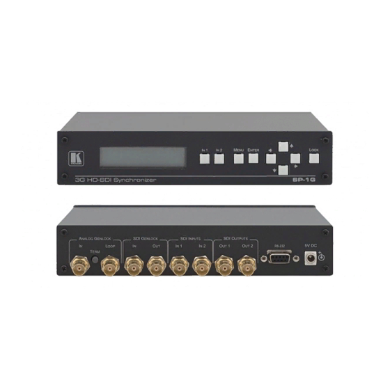
Page 8: Defining The Sp-1G 3G Hd-Sdi Synchronizer
Defining the SP-1G 3G HD-SDI Synchronizer Figure 1 defines the SP-1G. Figure 1: SP-1G 3G HD-SDI Synchronizer Feature Function Display Panel 2-line, 32-character LCD display IN 1 Button Press to select the signal on Input 1, lights when IN1 has an appropriate video signal;... - Page 9 Connects to SDI acceptor 1 Connector SDI Outputs OUT 2 BNC Connects to SDI acceptor 2 Connector RS-232 9-pin D-sub Port Connects to a PC or the remote controller 5V DC Power Connector Connect to the supplied 5V DC power adapter SP-1G - Overview...
-
Page 10: Connecting The Sp-1G 3G Hd-Sdi Synchronizer
Connecting the SP-1G 3G HD-SDI Synchronizer To connect the SP-1G as shown in the example in Figure 1. Connect up to two SDI input sources (for example, a video camera and SDI VTR) to the IN 1 or IN 2 BNC connectors. -
Page 11: Connecting The Sp-1G Via Rs-232
The SP-1G can be used as a clean switch as shown in the application in Figure To connect an 8x1 clean switch: 1. Connect the SDI OUTPUT of a switcher (for example, a VS-81HDxl) to the SDI INPUT of the SP-1G. -
Page 12: Operating The Sp-1G
5.2) Using the LCD Display The SP-1G includes a two-line, 16-character per line LCD display that displays (while in the main mode of operation) the device status, the genlock reference source and standard of video signals on SDI outputs. The following examples explain what is shown on the display. -
Page 13: Using The Front Panel Buttons
Selects the previous value of a selected parameter (with repeat function) RIGHT ► Selects the next value of a selected parameter (with repeat function) PANEL Enables or disables the PANEL LOCK function after pressing for 2 sec LOCK SP-1G - Operating the SP-1G... -
Page 14: Using The Sp-1G Menus
Using the SP-1G Menus This section explains how to operate the SP-1G using the various menus and their functions. The menu map in Figure 4 illustrates how to navigate through the various menus and their settings. Note: All menus below show SET1. as an example. Your setup numbers may differ. - Page 15 SP-1G - Using the SP-1G Menus...
-
Page 16: Figure 4: Sp-1G Menu Map
Figure 4: SP-1G Menu Map SP-1G - Using the SP-1G Menus... -
Page 17: Loading Setups
Note: Most parameter changes are temporarily saved in memory only until the SP-1G is powered OFF. To permanently save the change, perform SAVE SETTING AS A SETUP NUMBER as shown in this procedure. To save a setup: •... -
Page 18: Setting The Video Signal
1080p/23 576i/50 720p/59 1080i/59 1080sf/24 1080p/24 480i/60 720p/60 1080i/60 1080sf/25 1080p/25 1080sf/29 1080p/29 1080sf/30 1080p/30 1080p/50 1080p/59 1080p/60 Note: Each group contains its own mutually compatible standards • Press ENTER to activate the setting SP-1G - Using the SP-1G Menus... -
Page 19: Setting The Image Size And Position
Press MENU to enter the menu mode • Press ▼ or ▲ until SET1. IMAGE SIZE / POS (enter submenu) is displayed • Press ENTER go into the submenu • Press ▼ and ▲ to navigate through the submenu SP-1G - Using the SP-1G Menus... - Page 20 Press ▼ or ▲ until SET1 Vertical Position appears, press ◄ to shift vertically the image to the top of the screen in 0.2% steps and ► to shift downwards by the same amount SP-1G - Using the SP-1G Menus...
-
Page 21: Setting The Genlock
Press ENTER to save the setting temporarily (until powered down) 6.6.3 Setting the Genlock Reference Source Use the genlock reference source to select either a dedicated genlock input or any one of the four SDI inputs. SP-1G - Using the SP-1G Menus... - Page 22 ► to retard the timing • Press ENTER to save the setting temporarily (until powered down) • Save the new horizontal timing using the procedure Saving Setups in Section 6.2 SP-1G - Using the SP-1G Menus...
-
Page 23: Setting The No-Signal Screen
Press ◄ or ► to choose the settings: 0x18 (default), 0x19 • Press ENTER to save the setting Note: This assignment affects all 16 setups (presets) after ENTER is pressed. The setting is saved with auto power-down. SP-1G - Using the SP-1G Menus... -
Page 24: Displaying Status
• Press ◄ or ► to change the settings from 0% to 100% (50% default) Note: This assignment affects all 16 setups (presets) after ENTER is pressed. The setting is saved with auto power-down. SP-1G - Using the SP-1G Menus... -
Page 25: Enabling And Activating The Genlock Input Video Function
Press the ▲ Up button to switch the Genlock input signal to both outputs. Both Input buttons light • Press either of the Input buttons to cancel and return the input selection to normal operation SP-1G - Using the SP-1G Menus... -
Page 26: Technical Specifications
Technical Specifications The SP-1G technical specifications are shown in the following table. INPUTS: 2 SDI/HD-SDI, 1 genlock 75Ω on BNC connectors OUTPUTS: 2 SDI/HD-SDI, 1 genlock 75Ω on BNC connectors CONTROLS: 9 front panel buttons, RS-232 POWER CONSUMPTION: 5V DC, 1.2A OPERATING TEMPERATURE: 0°... -
Page 27: Kramer Protocol 2000
Kramer Protocol 2000 Protocol 2000 for the SP-1G is described below. For RS-232, data is at 9600 baud, no parity, 8 data bits, and 1 stop bit. All values shown are hexadecimal. Supported Commands (I value in decimal) Command Comments Reset PC →... - Page 28 (This source can be selected between either dedicated genlock SDI input or Analog input, see parameter D = 71 – genlock reference source). If genlock is turned off, forced standard is used SP-1G - Kramer Protocol 2000...
- Page 29 256 (signed) High Byte of Vertical E1 = Floor (V/256) i.e. Greatest signed integer Timing V less or equal to (V/256) where V = -625 to +625 1 line step V = 0 – default SP-1G - Kramer Protocol 2000...
- Page 31 For the latest information on our products and a list of Kramer distributors, visit our Web site where updates to this user manual may be found. We welcome your questions, comments, and feedback. Web site: www.kramerelectronics.com E-mail: info@kramerel.com SAFETY WARNING...
Need help?
Do you have a question about the SP-1G and is the answer not in the manual?
Questions and answers