
Related Manuals for Kramer DSP-62-UC


Summary of Contents for Kramer DSP-62-UC
- Page 1 USER MANUAL MODELS: DSP-62-AEC, DSP-62-UC Digital Sound Processor P/N: 2900-301432 Rev 2 www.kramerAV.com...
-
Page 2: Table Of Contents
Kramer Electronics Ltd. Contents Introduction Getting Started Overview of DSP-62-AEC, DSP-62-UC Typical Applications Defining DSP-62-AEC, DSP-62-UC DSP-62-AEC, DSP-62-UC Front Panels DSP-62-AEC, DSP-62-UC Rear Panels Mounting the Device Connecting DSP-62-AEC Connecting DSP-62-UC Connecting the Output to a Balanced/Unbalanced Stereo Audio Acceptor... -
Page 3: Introduction
Kramer Electronics Ltd. Introduction Welcome to Kramer Electronics! Since 1981, Kramer Electronics has been providing a world of unique, creative, and affordable solutions to the vast range of problems that confront the video, audio, presentation, and broadcasting professional on a daily basis. In recent years, we... -
Page 4: Overview Of Dsp-62-Aec, Dsp-62-Uc
European Advanced Recycling Network (EARN) and will cover any costs of treatment, recycling and recovery of waste Kramer Electronics branded equipment on arrival at the EARN facility. For details of Kramer’s recycling arrangements in your particular country go to our recycling pages at www.kramerav.com/il/quality/environment. - Page 5 HDBT, users can use the USB to connect a mouse, webcam, USB flash drive, or any other USB device to the TX-590RX (for example) side and take control of the PC that is connected to the DSP-62-UC. •...
-
Page 6: Typical Applications
Controlling your Device Control the device directly via the front panel HDMI select buttons: • By RS-232 serial commands transmitted by a touch screen system, PC, or other serial controller. • Via the Ethernet using built-in user-friendly webpages. DSP-62-AEC, DSP-62-UC – Introduction... -
Page 7: Defining Dsp-62-Aec, Dsp-62-Uc
Kramer Electronics Ltd. Defining DSP-62-AEC, DSP-62-UC This section defines DSP-62-AEC and DSP-62-UC front panels. DSP-62-AEC, DSP-62-UC Front Panels Figure 1: DSP-62-AEC Front Panel Figure 2: DSP-62-UC Front Panel Feature Function SETUP DIP-switches For factory use only. HDMI IN 1 Button Press to select HDMI IN 1 input (on the front panel). -
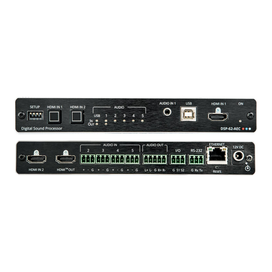
Page 8: Dsp-62-Aec, Dsp-62-Uc Rear Panels
IP settings. DSP-62-AEC 12V DC Power Connect to the power supply and to the mains electricity. Connector DSP-62-UC 48V DC Power Connect to the power supply and to the mains electricity. Connector DSP-62-AEC, DSP-62-UC – Defining DSP-62-AEC, DSP-62-UC... -
Page 9: Mounting The Device
For more information, go to www.kramerav.com/downloads/DSP-62-AEC http://www.kramerav.com/downloads/DSP-62-UC Mount the device inside a TBUS (for example, the TBUS-10XL): • Use the designated TBUS frame, to mount device inside the TBUS-10XL (see www.kramerav.com/downloads/TBUS-10XL). DSP-62-AEC, DSP-62-UC – Mounting the Device... -
Page 10: Connecting Dsp-62-Aec
(for example, a powered speaker) . 8. Connect a control system to the ETHERNET RJ-45 port 9. Connect the 12V DC power adapter to DSP-62-AEC to the mains electricity (not shown Figure DSP-62-AEC, DSP-62-UC – Mounting the Device... -
Page 11: Connecting Dsp-62-Uc
Figure 6: Connecting to DSP-62-UC To connect DSP-62-UC as illustrated in Figure 1. Connect an unbalanced stereo audio source (for example, an MP3 device) to the AUDIO IN 1 3.5mm mini jack... -
Page 12: Connecting The Output To A Balanced/Unbalanced Stereo Audio Acceptor
5 Audio IN LEDs to indicate that a signal is present (green), clipping is detected (red), and for LEDs 2 to 5, that a microphone is connected (blue). • One AUDIO OUT LED to indicate that a signal is present (green), or clipping is detected (red). DSP-62-AEC, DSP-62-UC – Mounting the Device... -
Page 13: Connecting Through Ethernet
3. Highlight the network adapter you want to use to connect to the device > click Change settings of this connection. The Local Area Connection Properties window for the selected network adapter opens as shown in Figure DSP-62-AEC, DSP-62-UC – Mounting the Device... - Page 14 Version 6 (TCP/IPv6) or Internet Protocol Version 4 (TCP/IPv4). 5. Click Properties. The Internet Protocol Properties window relevant to your IT system opens as shown in Figure 10 Figure Figure 10: Internet Protocol Version 4 Properties Window DSP-62-AEC, DSP-62-UC – Mounting the Device...
- Page 15 You can connect the device’s Ethernet port to the Ethernet port on a network hub or using a straight-through cable with RJ-45 connectors. Configuring Ethernet Port You can set the Ethernet parameters via the embedded webpages. DSP-62-AEC, DSP-62-UC – Mounting the Device...
-
Page 16: Using The Embedded Webpages
To browse the device’s webpages: 1. Open your Internet browser. 2. Type the device’s IP Address in the Address bar of your browser. For example, the default IP Address: 3. The authentication page appears. DSP-62-AEC, DSP-62-UC – Using the Embedded Webpages... -
Page 17: Using The Top Status Bar
The top status bar enables: • Viewing Current Analog I/O Configuration and Preset Name on page 16. • Changing Security Settings on page 16. • Entering /exiting full-screen display view by clicking the display-view icon ( DSP-62-AEC, DSP-62-UC – Using the Embedded Webpages... - Page 18 1. Click the lock icon ( ) indicating that security is enabled. The following message appears: Figure 17: Disabling Security Message 2. Type the current password (Admin, by default). 3. Click OK. Security is disabled. DSP-62-AEC, DSP-62-UC – Using the Embedded Webpages...
-
Page 19: Viewing The Matrix Area
Figure 19: Matrix Area – Routing Path When opening the processing view, the sliders of the Inputs routed to the Outputs appear. Figure 20: Processing View – Inputs Routed to Outputs DSP-62-AEC, DSP-62-UC – Using the Embedded Webpages... -
Page 20: Processing Audio Signals
Note that different port types have different processing modules. In general: • Toggle the (off) / (on) button to enable/disable a processing module. The module is enabled while it is set to On and disabled when set to Off. DSP-62-AEC, DSP-62-UC – Processing Audio Signals... - Page 21 • Current maximum level indicator – displays the current maximum level and holds it until a higher value is detected. Figure 22: Level Measurement Indicators DSP-62-AEC, DSP-62-UC – Processing Audio Signals...
- Page 22 IN 1 is used as an example in this section. To adjust analog input parameters: 1. In the Navigation pane, click DSP. The DSP (Main) page appears. 2. Click IN 3. The IN 3 processing page appears. DSP-62-AEC, DSP-62-UC – Processing Audio Signals...
- Page 23 ▪ Click to select microphone mode and to activate condenser microphone (the title IN changes to MIC). When is OFF, microphone works as a dynamic microphone. Analog input parameters are adjusted. DSP-62-AEC, DSP-62-UC – Processing Audio Signals...
- Page 24 2. In your MacBook, navigate to Utilities > Audio Midi Setup. 3. In Audio Midi Setup, click the name of the input device such as “Built-In Microphone.” 4. Click the Format drop-down menu, and then select the sample rate. DSP-62-AEC, DSP-62-UC – Processing Audio Signals...
- Page 25 Change port name. ▪ Move the volume fader to set the left and right audio levels (both sliders are identical). ▪ Click to mute / unmute the input audio, respectively. HDMI audio parameters are adjusted. DSP-62-AEC, DSP-62-UC – Processing Audio Signals...
- Page 26 The levels of audio signals that fall below the set threshold level are reduced. To adjust the expander module: 1. In the Navigation pane, click DSP. The DSP (Main) page opens. 2. Click Exp. The button turns light blue and the Expander module page appears. DSP-62-AEC, DSP-62-UC – Processing Audio Signals...
- Page 27 1. In the Navigation pane, click DSP. The DSP (Main) page appears. 2. Click HPF. The button turns light orange and the High Pass Filter module page appears. The left side shows the input volume slider. DSP-62-AEC, DSP-62-UC – Processing Audio Signals...
- Page 28 1. In the Navigation pane, click DSP. The DSP (Main) page appears. 2. Click Comp. The button turns blue and the Compressor module pane appears. 3. Click the Off button . The Comp module turns on Figure 30: Processing View – Compressor Module DSP-62-AEC, DSP-62-UC – Processing Audio Signals...
- Page 29 Click BYPASS to ignore a band. ▪ Adjust the band Frequency (Hz). ▪ Set Bandwidth (Oct) to set the range of frequencies around the selected frequency. ▪ Set the bandwidth audio EQ Level (dB). Equalizer settings are adjusted. DSP-62-AEC, DSP-62-UC – Processing Audio Signals...
- Page 30 The AEC (Acoustic Echo Cancellation) module is a learning filter algorithm that, when enabled, filters the unwanted echoes in the room, such as room speakers. To enable/disable AEC delay: 1. In the Navigation pane, click DSP. The DSP (Main) page appears. DSP-62-AEC, DSP-62-UC – Processing Audio Signals...
- Page 31 2. Click Delay. The button turns green and the Equalizer processing page appears. 3. Click the Off button . The Delay module turns on Figure 34: Processing View – Delay Module 4. Set the delay. Delay setting is adjusted. DSP-62-AEC, DSP-62-UC – Processing Audio Signals...
- Page 32 Move the volume fader to set the output audio level (both sliders are identical). ▪ Toggle to mute / unmute the output audio, respectively. ▪ Click to inverse polarity (used for troubleshooting). Audio outputs are adjusted. DSP-62-AEC, DSP-62-UC – Processing Audio Signals...
- Page 33 The right side shows the output volume slider. 3. Click the Off button . The Limiter module turns on 4. Set the Threshold. Note the Gain Reduction meter as you change the threshold. Limiter settings are adjusted. DSP-62-AEC, DSP-62-UC – Processing Audio Signals...
-
Page 34: Routing Inputs To Outputs
The device enables performing the following functions: • Connecting Inputs to Outputs on page 33. • Setting Cross-Point Volume on page 35. • Linking Analog Pairs on page 36. DSP-62-AEC, DSP-62-UC – Processing Audio Signals... - Page 35 Kramer Electronics Ltd. Connecting Inputs to Outputs To route an input or several inputs to an output: 1. In the Navigation pane, click Matrix. The Matrix page appears. Figure 37: Matrix Page DSP-62-AEC, DSP-62-UC – Processing Audio Signals...
- Page 36 3. Click any other cross-points (one input to output/s or several inputs to output/s). Figure 39: Matrix Page – Multiple Input-Output Cross-Points Selected inputs are routed to selected outputs. You can also select an audio signal generator for testing. DSP-62-AEC, DSP-62-UC – Processing Audio Signals...
- Page 37 3. Set the cross-point volume using the knob or enter the value and pressing Enter (on your keyboard). The cross-point volume is set and appears at the cross-point. Figure 41: Cross-Point Volume Value Audio volume is set at the cross-point. DSP-62-AEC, DSP-62-UC – Processing Audio Signals...
-
Page 38: Mixing Audio Signals
2. Use the slider or enter the desired value and press Enter (on your PC) to set the volume. View the current gain and the input/output name (see Input / Output Channels Operation on page 19). DSP-62-AEC, DSP-62-UC – Processing Audio Signals... - Page 39 When the parameters change, the Default button turns yellow. Click Default to restore default settings. Figure 44: Mixer Page – Snapshots 3. Click Store. The Snapshot buttons turn green. Figure 45: Snapshot STORE option DSP-62-AEC, DSP-62-UC – Processing Audio Signals...
- Page 40 To load the previous snapshot configuration, click Prev to load the previous snapshot configuration. ▪ Click Last to load the latest configured snapshot (clicking Last again goes to the previously configured snapshot and so on). The selected snapshot is loaded. DSP-62-AEC, DSP-62-UC – Processing Audio Signals...
-
Page 41: Audio And Video Settings
10) and click LOAD, SAVE AS or SAVE. The current preset is loaded or saved. System Presets contain all the system configuration including Snapshot configuration and excluding IP settings. Audio settings are defined. DSP-62-AEC, DSP-62-UC – Audio and Video Settings... -
Page 42: Defining Video Settings
3. Enter HDMI input and output labels then click Set. 4. For HDMI input, check/ uncheck Force RGB and/or Force 2LPCM. 5. If required, select a video pattern from the drop-down box. Video settings are defined. DSP-62-AEC, DSP-62-UC – Audio and Video Settings... -
Page 43: Defining Hdmi Auto Switching
To configure auto switching: 1. From the Navigation List, select AV Settings. 2. In the Video Selection Mode list, select a video mode. High is the default. 3. Click SET VIDEO. Auto switching is set. DSP-62-AEC, DSP-62-UC – Audio and Video Settings... -
Page 44: Defining General Settings
Performing Firmware Upgrade on page 43. • Importing/Exporting Global Settings on page 44. • Restarting and Resetting the Device on page 45. • Defining Communication Settings on page 46. • Setting Access Security on page 47. DSP-62-AEC, DSP-62-UC – Defining General Settings... -
Page 45: Performing Firmware Upgrade
Perform device firmware upgrade via the General tab in the Device Settings page. To perform firmware upgrade: 1. In the Navigation pane, click Device Settings. The General tab in the Device Settings page appears. Figure 50: Upgrade Settings Tab – Upgrading the Firmware DSP-62-AEC, DSP-62-UC – Defining General Settings... -
Page 46: Importing/Exporting Global Settings
Click EXPORT to export a file: the current system setting “.bin” file is downloaded to your PC and can be exported to other devices. Figure 53: General Settings Tab – Importing / Exporting Global Settings Global system settings are imported/exported. DSP-62-AEC, DSP-62-UC – Defining General Settings... -
Page 47: Restarting And Resetting The Device
1. In the Navigation pane, click Device Settings. The Device Settings page appears. Figure 54: Device Settings Page - Restart 2. Click Restart. Figure 55: Device Restart Window 3. Click Proceed. Wait for the device to reload after the device restarts. Device has restarted. DSP-62-AEC, DSP-62-UC – Defining General Settings... -
Page 48: Defining Communication Settings
4. Click SAVE. 5. Enter the device name in the address bar of your browser to reload the page. You can read the new IP address from the Communication Settings page. DHCP is set to Off. DSP-62-AEC, DSP-62-UC – Defining General Settings... -
Page 49: Setting Access Security
By default, the webpages are secured and require access permission (user name and password are both Admin). DSP-62 enables performing the following security actions: • Disabling Security on page 48. • Enabling Security on page 49. • Changing the Password on page 49. DSP-62-AEC, DSP-62-UC – Defining General Settings... - Page 50 Figure 58: General Settings Tab – Security 3. Click Off. The following message appears. Figure 59: General Settings Tab – Security Message 4. Enter the current password and click OK. Security is disabled. The security-disabled icon appears ( DSP-62-AEC, DSP-62-UC – Defining General Settings...
- Page 51 3. Enter the current password. 4. Click CHANGE. Figure 61: General Settings Tab – Changing the Password 5. Enter the new password or use the suggested password. 6. Click SAVE. The password has changed. DSP-62-AEC, DSP-62-UC – Defining General Settings...
-
Page 52: Viewing Device Information
Kramer Electronics Ltd. Viewing Device Information In the Navigation pane, click About to view the DSP-62 webpage version and Kramer Electronics Ltd. details. Figure 62: About Page DSP-62-AEC, DSP-62-UC – Viewing Device Information... -
Page 53: Upgrading Firmware
The latest version of K-UPLOAD and installation instructions can be downloaded from our website at: www.kramerav.com/support/product_downloads.asp. Note that in order to use the micro USB port, you need to install the Kramer USB driver, available at: www.kramerav.com/support/product_downloads.asp. DSP-62-AEC, DSP-62-UC – Upgrading Firmware... -
Page 54: Technical Specifications
Shipping Dimensions (W, D, H) 34.5cm x 16.5cm x 5.2cm (13.6" x 6.5" x 2.1") Net Weight 0.16kg (0.4lbs) Shipping Weight 0.6kg (1.3lbs) approx. Accessories Included Power adapter cord Specifications are subject to change without notice at www.kramerav.com DSP-62-AEC, DSP-62-UC – Technical Specifications... -
Page 55: Dsp-62-Uc Technical Specifications
Shipping Dimensions (W, D, H) 35.1cm x 21.2cm x 7.2cm ( 13.81" x 8.34" x 2.83") Net Weight 0.7kg (1.54lbs) Shipping Weight 1.29kg (2.84lbs) approx. Accessories Included Power adapter cord Specifications are subject to change without notice at www.kramerav.com DSP-62-AEC, DSP-62-UC – Technical Specifications... -
Page 56: Default Communication Parameters
Additional descriptors... None Preferred timing..Yes Native/preferred timing.. 1920x1080p at 60Hz (16:9) Modeline...."1920x1080" 148.500 1920 2008 2052 2200 1080 1084 1089 1125 +hsync +vsync Standard timings supported 720 x 400p at 70Hz - IBM VGA DSP-62-AEC, DSP-62-UC – Technical Specifications... - Page 57 Rear left/right center... No Rear LFE....No Report information Date generated... 02/12/2020 Software revision..2.91.0.1043 Data source....File - NB: improperly installed Operating system..10.0.18363.2 Raw data 00,FF,FF,FF,FF,FF,FF,00,2D,B2,00,12,00,00,00,00,FF,1C,01,03,80,34,20,78,E2,B3,25,AC,51,30,B4,26, 10,50,54,FF,FF,80,81,8F,81,99,A9,40,61,59,45,59,31,59,71,4A,81,40,02,3A,80,18,71,38,2D,40,58,2C, 45,00,A0,5A,00,00,00,1E,00,00,00,FF,00,32,39,35,2D,38,38,33,34,35,30,31,30,30,00,00,00,FC,00,44, 53,50,2D,36,32,2D,41,45,43,0A,20,20,00,00,00,FD,00,38,4C,1E,53,11,00,0A,20,20,20,20,20,20,01,5C, 02,03,1B,C1,23,09,07,07,48,90,05,04,03,02,07,16,01,65,03,0C,00,10,00,83,01,00,00,02,3A,80,18,71, 38,2D,40,58,2C,45,00,07,44,21,00,00,1E,01,1D,80,18,71,1C,16,20,58,2C,25,00,07,44,21,00,00,9E,01, 1D,00,72,51,D0,1E,20,6E,28,55,00,07,44,21,00,00,1E,8C,0A,D0,8A,20,E0,2D,10,10,3E,96,00,07,44,21, 00,00,18,00,00,00,00,00,00,00,00,00,00,00,00,00,00,00,00,00,00,00,00,00,00,00,00,00,00,00,00,77 DSP-62-AEC, DSP-62-UC – Technical Specifications...
-
Page 58: Default Edid For Dsp-62-Uc
480i at 60Hz - Doublescan (16:9, 32:27) 720 x 576i at 50Hz - Doublescan (16:9, 64:45) 640 x 480p at 60Hz - Default (4:3, 1:1) NB: NTSC refresh rate = (Hz*1000)/1001 CE vendor specific data (VSDB) DSP-62-AEC, DSP-62-UC – Technical Specifications... - Page 59 Rear left/right center... No Rear LFE....No Report information Date generated... 9/12/2021 Software revision..2.91.0.1043 Data source....File - NB: improperly installed Operating system..10.0.18363.2 Raw data 00,FF,FF,FF,FF,FF,FF,00,2D,B2,00,12,00,00,00,00,FF,1C,01,03,80,34,20,78,E2,B3,25,AC,51,30,B4,26, 10,50,54,FF,FF,80,81,8F,81,99,A9,40,61,59,45,59,31,59,71,4A,81,40,02,3A,80,18,71,38,2D,40,58,2C, 45,00,A0,5A,00,00,00,1E,00,00,00,FF,00,32,39,35,2D,38,38,33,34,35,30,31,30,30,00,00,00,FC,00,44, 53,50,2D,36,32,2D,55,43,0A,20,20,20,00,00,00,FD,00,38,4C,1E,53,11,00,0A,20,20,20,20,20,20,01,6D, 02,03,1B,C1,23,09,07,07,48,90,05,04,03,02,07,16,01,65,03,0C,00,10,00,83,01,00,00,02,3A,80,18,71, 38,2D,40,58,2C,45,00,07,44,21,00,00,1E,01,1D,80,18,71,1C,16,20,58,2C,25,00,07,44,21,00,00,9E,01, 1D,00,72,51,D0,1E,20,6E,28,55,00,07,44,21,00,00,1E,8C,0A,D0,8A,20,E0,2D,10,10,3E,96,00,07,44,21, 00,00,18,00,00,00,00,00,00,00,00,00,00,00,00,00,00,00,00,00,00,00,00,00,00,00,00,00,00,00,00,77 DSP-62-AEC, DSP-62-UC – Technical Specifications...
-
Page 60: Protocol 3000
Kramer Electronics Ltd. Protocol 3000 Kramer devices can be operated using Kramer Protocol 3000 commands sent via serial or Ethernet ports. Understanding Protocol 3000 Protocol 3000 commands are a sequence of ASCII letters, structured according to the following. • Command format:... -
Page 61: Protocol 3000 Commands
1 – indicates that EDID data is copied to this destination. – safe_mode 0 – device accepts the EDID as is without trying to adjust 1 – device tries to adjust the EDID (default value if no parameter is sent) DSP-62-AEC, DSP-62-UC – Protocol 3000... - Page 62 0 to 100 For release time [ms] 0 to 10K For threshold [dB] -100 to 0 For ratio [1 to 100]:1 For gain compensation [dB] -100 to +15 For bypass [ms] 0– off 1 – on DSP-62-AEC, DSP-62-UC – Protocol 3000...
- Page 63 – The port number as printed on the front or rear panel ▪<signal_type> – o AUDIO ▪<index> – 1 to 2 value – For delay time [ms] 0 to 150 For bypass [ms] 0– off 1 – on DSP-62-AEC, DSP-62-UC – Protocol 3000...
- Page 64 0– global bypass 1,2,3,4 – for each band value – For level [dB] -24 to +24 For freq [Hz] 20 to 20K For qfactor [Oct] 0.05 to 4 For bypass [ms] 0– off 1 – on DSP-62-AEC, DSP-62-UC – Protocol 3000...
- Page 65 ~nn@DSP-HPFfield_id,<direction_type>.<port_type>.<port_i as printed on the front or rear ndex>.<signal_type>.<index>,value<CR><LF> panel 2 to 5 ▪<signal_type> – o AUDIO ▪<index> – 1 value – For freq [Hz] 20 to 20K For bypass 0– off 1 – on DSP-62-AEC, DSP-62-UC – Protocol 3000...
- Page 66 – The port number rt_index>.<signal_type>.<index>,value<CR><LF> as printed on the front or rear panel – ▪<signal_type> o AUDIO – 1 to 2 ▪<index> value – For threshold [dB] -100 to 0 For bypass 0– Off 1 – On DSP-62-AEC, DSP-62-UC – Protocol 3000...
- Page 67 – The port number as printed on the front or rear panel 1 to 5 ▪<signal_type> – o AUDIO ▪<index> – 1 value – For level [dB] -100 to +15 For mute 0– Off 1 – On DSP-62-AEC, DSP-62-UC – Protocol 3000...
- Page 68 – for mode 1– Tone 2 – Pink noise For tone-freq [Hz] 20 to 20K For tone-level [dB] -100 to +15 For pink-level [dB] -100 to +15 For bypass 0– Off 1 – On DSP-62-AEC, DSP-62-UC – Protocol 3000...
- Page 69 #FACTORY<CR> FEEDBACK This command ~nn@FACTORYOK<CR><LF> deletes all user data from the device. The deletion can take some time. Your device may require powering off and powering on for the changes to take effect. DSP-62-AEC, DSP-62-UC – Protocol 3000...
- Page 70 1=High. In all other modes an error message is sent. The device uses this command to notify the user of any change regarding the step and voltage in: In digital mode the answer is 0 (low), 1 (high). DSP-62-AEC, DSP-62-UC – Protocol 3000...
- Page 71 – HDCP mode: mode HDCP supported - 0 – HDCP Off HDCP_ON [default]. 3 – HDCP defined according to the connected output HDCP not supported - HDCP OFF. HDCP support changes following detected sink - MIRROR OUTPUT. DSP-62-AEC, DSP-62-UC – Protocol 3000...
- Page 72 The permission system works only if security is enabled with the “SECUR” command. LOGOUT Cancel current COMMAND #LOGOUT<CR> permission level. #LOGOUT<CR> FEEDBACK Logs out from End ~nn@LOGOUTOK<CR><LF> User or Administrator permission levels to Not Secure. DSP-62-AEC, DSP-62-UC – Protocol 3000...
- Page 73 (if there are more than one). #NET-CONFIG?id<CR> Counting is 0 based, meaning the FEEDBACK control port is ‘0’, additional ports are ~nn@NET-CONFIGid,ip,net_mask,gateway<CR><LF> 1,2,3…. – Network IP – Network mask net_mask – Network gateway gateway DSP-62-AEC, DSP-62-UC – Protocol 3000...
- Page 74 FEEDBACK MASK255.255.000.000<CR `administrator. command is ~nn@NET-MASKnet_mask<CR><LF> obsolete) > net_mask – Format: xxx.xxx.xxx.xxx NET-MASK? Get subnet mask. COMMAND Get the subnet mask: #NET-MASK?<CR> #NET-MASK?<CR> (NET-CONFIG is recommended as this FEEDBACK command is ~nn@NET-MASKnet_mask<CR><LF> obsolete) DSP-62-AEC, DSP-62-UC – Protocol 3000...
- Page 75 1 to 2 – 14 decimal digits, serial_number Get device serial COMMAND Get the device serial number: number. factory assigned #SN?<CR> #SN?<CR> FEEDBACK ~nn@SNserial_number<CR><LF> DSP-62-AEC, DSP-62-UC – Protocol 3000...
- Page 76 – 0 – Off 1 – On – XX.XX.XXXX firmware_version VERSION? Get firmware version COMMAND Get the device firmware number. version number: #VERSION?<CR> where the digit groups are: major.minor.build version #VERSION?<CR> FEEDBACK ~nn@VERSIONfirmware_version<CR><LF> DSP-62-AEC, DSP-62-UC – Protocol 3000...
- Page 77 1 to 5. ▪ – <signal_type> o AUDIO ▪ <index> – Indicates a specific channel number when there are multiple channels of the same type 1 to 2. – mode 1 – Line 2 – Mic DSP-62-AEC, DSP-62-UC – Protocol 3000...
- Page 78 This is an Extended Protocol 3000 command. Used essentially by the web command. DSP-62-AEC, DSP-62-UC – Protocol 3000...
- Page 79 ▪ – <signal_type> o AUDIO ▪ <index> – Indicates a specific channel number when there are multiple channels of the same type ▪ audio_level – [-100,24] dB with a resolution of 0.1 dB. DSP-62-AEC, DSP-62-UC – Protocol 3000...
- Page 80 – The port number <port_index> as printed on the front or rear panel ▪ – <signal_type> o AUDIO ▪ <index> – Indicates a specific channel number when there are multiple channels of the same type ▪ – <mute_state> DSP-62-AEC, DSP-62-UC – Protocol 3000...
- Page 81 <index> channel number when there are multiple channels of the same type Pattern_id –pattern ID o 0 : none o 1 : Color bar o 2 Blue screen o 3: Green screen 4: Red screen DSP-62-AEC, DSP-62-UC – Protocol 3000...
- Page 82 Presets inside the same system. To get the list of preset types existing in your product use the command: X-PRST-TYPES? This is an Extended Protocol 3000 command. DSP-62-AEC, DSP-62-UC – Protocol 3000...
- Page 83 Presets inside the same system. To get the list of preset types existing in your product use the command: X-PRST-TYPES? This is an Extended Protocol 3000 command. DSP-62-AEC, DSP-62-UC – Protocol 3000...
- Page 84 Presets inside the same system. To get the list of preset types existing in your product use the command: X-PRST-TYPES? This is an Extended Protocol 3000 command. DSP-62-AEC, DSP-62-UC – Protocol 3000...
- Page 85 VIDEO command and are ▪ <index> – Indicates a specific implied even if not channel number when there are written. multiple channels of the same type This is an Extended Protocol 3000 command. DSP-62-AEC, DSP-62-UC – Protocol 3000...
-
Page 86: Result And Error Codes
ERR_RESERVED_8 (Reserved) ERR_RESERVED_9 (Reserved) ERR_RESERVED_10 (Reserved) ERR_RESERVED_11 (Reserved) ERR_RESERVED_12 (Reserved) ERR_EDID_CORRUPTED EDID corrupted ERR_NON_LISTED Device specific errors File has the same CRC – not changed ERR_SAME_CRC ERR_WRONG_MODE Wrong operation mode ERR_NOT_CONFIGURED Device/chip was not initialized DSP-62-AEC, DSP-62-UC – Protocol 3000... - Page 87 This limited warranty gives you specific legal rights, and you may have other rights which vary from country to country or state to state. This limited warranty is void if (i) the label bearing the serial number of this product has been removed or defaced, (ii) the product is not distributed by Kramer Electronics or (iii) this product is not purchased from an authorized Kramer Electronics reseller.
- Page 88 SAFETY WARNING Disconnect the device from the power supply before opening and servicing. For the latest information on our products and a list of Kramer distributors, visit our website where updates to this user manual may be found. We welcome your questions, comments, and feedback.
Need help?
Do you have a question about the DSP-62-UC and is the answer not in the manual?
Questions and answers