Table of Contents
Advertisement
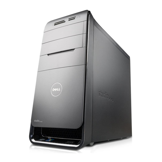
Dell™ Studio XPS™ 7100 Service Manual
Before You Begin
Technical Overview
Computer Cover
Memory Module(s)
Front Bezel
Graphics Card Bracket
PCI and PCI Express Cards
Drives
Top Cover
Top I/O Panel
Notes, Cautions, and Warnings
NOTE:
A NOTE indicates important information that helps you make better use of your computer.
CAUTION:
A CAUTION indicates either potential damage to hardware or loss of data and tells you how to avoid the problem.
WARNING:
A WARNING indicates a potential for property damage, personal injury, or death.
Information in this document is subject to change without notice.
© 2010 Dell Inc. All rights reserved.
Reproduction of these materials in any manner whatsoever without the written permission of Dell Inc. is strictly forbidden.
Trademarks used in this text: Dell, the DELL logo, and Studio XPS are trademarks of Dell Inc.; AMD is a registered trademark of Advanced Micro Devices, Inc.; Microsoft, Windows,
and the Windows start button logo are either trademarks or registered trademarks of Microsoft Corporation in the United States and/or other countries.
Other trademarks and trade names may be used in this document to refer to either the entities claiming the marks and names or their products. Dell Inc. disclaims any
proprietary interest in trademarks and trade names other than its own.
May 2010 Rev. A00
Model: D03M series Type: D03M002
Front USB Panel
Bluetooth Assembly
Power Button Module
Fans
Processor
Coin-Cell Battery
Power Supply
System Board
System Setup
Flashing the BIOS
Advertisement
Table of Contents

Related Manuals for Dell Studio XPS 7100


Summary of Contents for Dell Studio XPS 7100
- Page 1 Reproduction of these materials in any manner whatsoever without the written permission of Dell Inc. is strictly forbidden. Trademarks used in this text: Dell, the DELL logo, and Studio XPS are trademarks of Dell Inc.; AMD is a registered trademark of Advanced Micro Devices, Inc.; Microsoft, Windows, and the Windows start button logo are either trademarks or registered trademarks of Microsoft Corporation in the United States and/or other countries.
-
Page 2: Before You Begin
A component can be replaced or—if purchased separately—installed by performing the removal procedure in reverse order. Technical Specifications For information on technical specifications of your computer, see the Setup Guide at support.dell.com/manuals. Recommended Tools The instructions in this document may require the following tools: Small flat-blade screwdriver... - Page 3 1. Ensure that the work surface is flat and clean to prevent the computer cover from being scratched. 2. Turn off your computer (see Turning Off Your Computer) and all attached devices. CAUTION: To disconnect a network cable, first unplug the cable from your computer and then unplug the cable from the network device. ...
-
Page 4: Removing The Front Bezel
WARNING: Before working inside your computer, read the safety information that shipped with your computer. For additional safety best practices information, see the Regulatory Compliance Homepage at www.dell.com/regulatory_compliance. WARNING: To guard against electrical shock, always unplug your computer from the electrical outlet before removing the cover. - Page 5 2. Align and insert the front bezel clamps into the front panel slots. 3. Rotate the front bezel towards the computer until the front bezel tabs snap into place. 1 front bezel 2 front panel slots (3) 3 front bezel tabs (4) 4 front panel 5 front bezel clamps (3) ...
-
Page 6: Flashing The Bios
The BIOS may require flashing when an update is available or when replacing the system board. To flash the BIOS: 1. Turn on the computer. 2. Go to support.dell.com/support/downloads. 3. Locate the BIOS update file for your computer. NOTE: The Service Tag for your computer is located on a label on the top of your computer. -
Page 7: Removing The Bluetooth Assembly
WARNING: Before working inside your computer, read the safety information that shipped with your computer. For additional safety best practices information, see the Regulatory Compliance Homepage at www.dell.com/regulatory_compliance. WARNING: To guard against electrical shock, always unplug your computer from the electrical outlet before removing the cover. - Page 8 2. Slide the Bluetooth assembly cable through the slot in the front panel. 3. Align the Bluetooth assembly tab with the Bluetooth assembly slot in the front panel. 4. Press in on the Bluetooth assembly tab, and push it towards the front panel until it clicks into place. ...
-
Page 9: Pci And Pci Express Cards
WARNING: Before working inside your computer, read the safety information that shipped with your computer. For additional safety best practices information, see the Regulatory Compliance Homepage at www.dell.com/regulatory_compliance. WARNING: To guard against electrical shock, always unplug your computer from the electrical outlet before removing the cover. -
Page 10: Removing Pci And Pci Express Cards
1 guide clamps (2) 2 card retention bracket 3 alignment bar 4 alignment guide 5 filler bracket 6 guide notches (2) 7 screw Removing PCI and PCI Express Cards 1. Follow the instructions in Before You Begin. 2. Remove the computer cover (see Removing the Computer Cover). -
Page 11: Replacing Pci And Pci Express Cards
NOTE: Installing filler brackets over empty card-slot openings is necessary to maintain FCC certification of the computer. The brackets also keep dust and dirt out of your computer. Replacing PCI and PCI Express Cards 1. Follow the instructions in Before You Begin. - Page 12 Disabled. Enabled. 3. Connect the network 3. Connect the network cable to the network cable to the integrated card's connector. network connector. Back to Contents Page ...
-
Page 13: Removing The Coin-Cell Battery
WARNING: Before working inside your computer, read the safety information that shipped with your computer. For additional safety best practices information, see the Regulatory Compliance Homepage at www.dell.com/regulatory_compliance. WARNING: A new battery can explode if it is incorrectly installed. Replace the battery only with the same or equivalent type recommended by the manufacturer. - Page 14 1 coin-cell battery 2 battery socket 3. Replace the computer cover (see Replacing the Computer Cover). 4. Connect your computer and devices to electrical outlets, and then turn them on. 5. Enter system setup (see System Setup) and restore the settings you recorded in step Back to Contents Page ...
-
Page 15: Removing The Computer Cover
WARNING: Before working inside your computer, read the safety information that shipped with your computer. For additional safety best practices information, see the Regulatory Compliance Homepage at www.dell.com/regulatory_compliance. WARNING: To guard against likelihood of electric shock, laceration by moving fan blades, or other unexpected injuries, always unplug your computer from the electrical outlet before removing the cover. - Page 16 thumbscrew slots computer cover 7. Place the computer in an upright position. Back to Contents Page ...
-
Page 17: Removing The Processor
CAUTION: Do not perform the following steps unless you are familiar with hardware removal and replacement. Performing these steps incorrectly could damage your system board. To contact Dell for technical service, see the Setup Guide. Removing the Processor ... -
Page 18: Replacing The Processor
CAUTION: When removing the processor, do not touch any of the pins inside the socket or allow any objects to fall on the pins in the socket. 5. Gently lift the processor to remove it from the socket. Leave the release lever extended in the release position so that the socket is ready for the new processor. Replacing the Processor ... - Page 19 10. Replace the computer cover (see Replacing the Computer Cover). Back to Contents Page ...
-
Page 20: Hard Drive
WARNING: Before working inside your computer, read the safety information that shipped with your computer. For additional safety best practices information, see the Regulatory Compliance Homepage at www.dell.com/regulatory_compliance. WARNING: To guard against electrical shock, always unplug your computer from the electrical outlet before removing the cover. -
Page 21: Removing The Hard Drive Cage
Removing the Hard Drive Cage 1. Follow the instructions in Before You Begin. 2. Remove the computer cover (see Removing the Computer Cover). 3. Remove the primary hard drive (see Removing the Primary Hard Drive). 4. -
Page 22: Replacing The Secondary Hard Drive
screws (4) hard drive cage secondary hard drive Replacing the Secondary Hard Drive 1. Follow the instructions in Before You Begin. 2. Check the documentation that shipped with the drive to verify that it is configured for your computer. ... -
Page 23: Optical Drive
10. Check the System Setup for drive configuration changes (see System Setup). Optical Drive Removing the Optical Drive 1. Follow the instructions in Before You Begin. 2. Remove the computer cover (see Removing the Computer Cover). ... - Page 24 screw 3. To install a secondary optical drive, insert a screw driver and twist it to remove the break-away metal plate. 4. Pull the break-away metal plate away from the chassis. break-away metal plate 5. Gently slide the optical drive into the optical drive bay through the front of the computer. ...
-
Page 25: Media Card Reader
Media Card Reader Removing the Media Card Reader 1. Follow the instructions in Before You Begin. 2. Remove the computer cover (see Removing the Computer Cover). 3. Remove the front bezel (see Removing the Front Bezel). ... - Page 26 7. Replace the front bezel (see Replacing the Front Bezel). 8. Replace the computer cover (see Replacing the Computer Cover). 9. Connect your computer and devices to electrical outlets, and then turn them on. Back to Contents Page ...
-
Page 27: Chassis Fan
WARNING: Before working inside your computer, read the safety information that shipped with your computer. For additional safety best practices information, see the Regulatory Compliance Homepage at www.dell.com/regulatory_compliance. WARNING: To guard against electrical shock, always unplug your computer from the electrical outlet before removing the cover. -
Page 28: Processor Fan And Heat Sink Assembly
4. Connect the chassis fan cable to the system board connector SYS_FAN1 (see System Board Components). 5. Replace the computer cover (see Replacing the Computer Cover). Processor Fan and Heat Sink Assembly WARNING: Despite having a plastic shield, the processor fan and heat sink assembly may be very hot during normal operation. Ensure that it has had sufficient time to cool before you touch it. - Page 29 3. Apply new thermal grease to the top of the processor. 4. Place the processor fan and heatsink assembly over the processor. 5. Align the clamps on the processor fan and heatsink assembly with the tabs on the bracket. ...
-
Page 30: Removing The Front Usb Panel
WARNING: Before working inside your computer, read the safety information that shipped with your computer. For additional safety best practices information, see the Regulatory Compliance Homepage at www.dell.com/regulatory_compliance. WARNING: To guard against electrical shock, always unplug your computer from the electrical outlet before removing the cover. -
Page 31: Replacing The Front Usb Panel
Replacing the Front USB Panel CAUTION: Take care not to damage the cable connectors and the cable routing clips when sliding the front USB panel into the front USB panel clamp slot. 1. Follow the instructions in Before You Begin. -
Page 32: Removing The Graphics Card Bracket
WARNING: Before working inside your computer, read the safety information that shipped with your computer. For additional safety best practices information, see the Regulatory Compliance Homepage at www.dell.com/regulatory_compliance. WARNING: To guard against electrical shock, always unplug your computer from the electrical outlet before removing the cover. - Page 33 ...
-
Page 34: Removing The Memory Module(S)
WARNING: Before working inside your computer, read the safety information that shipped with your computer. For additional safety best practices information, see the Regulatory Compliance Homepage at www.dell.com/regulatory_compliance. WARNING: To guard against electrical shock, always unplug your computer from the electrical outlet before removing the cover. - Page 35 1 matched memory modules in DIMM 2 matched memory modules in DIMM connectors 1 and 2 (white securing connectors 3 and 4 (black securing clips) clips) 3. Align the notch on the bottom of the memory module with the tab in the connector. cutouts (2) notch memory module...
- Page 36 ® ® 8. Right-click the My Computer icon on your Microsoft Windows desktop and click Properties. 9. Click the General tab. 10. To verify that the memory is installed correctly, check the amount of memory (RAM) listed. Back to Contents Page ...
-
Page 37: Removing The Power Supply
WARNING: Before working inside your computer, read the safety information that shipped with your computer. For additional safety best practices information, see the Regulatory Compliance Homepage at www.dell.com/regulatory_compliance. WARNING: To guard against electrical shock, always unplug your computer from the electrical outlet before removing the cover. - Page 38 WARNING: Failure to replace and tighten all screws may cause electrical shock as these screws are a key part of the system grounding. 4. Replace the four screws that secure the power supply to the chassis. 5. Connect the DC power cables to the system board and drives (see System Board Components).
-
Page 39: Removing The Power Button Module
WARNING: Before working inside your computer, read the safety information that shipped with your computer. For additional safety best practices information, see the Regulatory Compliance Homepage at www.dell.com/regulatory_compliance. WARNING: To guard against electrical shock, always unplug your computer from the electrical outlet before removing the cover. - Page 40 2. Align and push the power button module tabs into the slots on the top panel. 3. Connect the power button module cable to the system board connector FP1 (see System Board Components). 4. Replace the top cover (see Replacing the Top Cover).
-
Page 41: Removing The System Board
WARNING: Before working inside your computer, read the safety information that shipped with your computer. For additional safety best practices information, see the Regulatory Compliance Homepage at www.dell.com/regulatory_compliance. WARNING: To guard against electrical shock, always unplug your computer from the electrical outlet before removing the cover. -
Page 42: Replacing The System Board
6. Replace the processor fan and the heat sink assembly (see Replacing the Processor Fan and Heat Sink Assembly). CAUTION: Only a certified service technician should perform repairs on your computer. Damage due to servicing that is not authorized by Dell™ is not covered by your warranty. CAUTION: Ensure that the heat sink assembly is correctly seated and secure. -
Page 43: System Setup Options
1. Turn on (or restart) your computer. 2. When the DELL™ logo is displayed, watch for the F2 prompt to appear and then press <F2> immediately. NOTE: The F2 prompt indicates that the keyboard has initialized. This prompt can appear very quickly, so you must watch for it to display, and then press <F2>. If you press <F2> before you are prompted, this keystroke will be lost. If you wait too long and the operating system logo appears, continue to wait until you see the Microsoft® Windows® desktop. - Page 44 Displays the processor L1 cache size Processor Cache L1 Displays the processor L2 cache size Processor Cache L2 Displays the processor L3 cache size Processor Cache L3 Indicates the amount of installed memory in MB Memory Installed Indicates the amount of memory available in MB Memory Available Indicates the memory speed in MHz Memory Speed...
-
Page 45: Clearing Forgotten Passwords
Status of user installed User Password Allows to set the desired supervisor password Set Supervisor Password Exit Provides options to Load Default, Save and Exit Setup, and Exit Without Saving Exit Options Clearing Forgotten Passwords WARNING: Before you begin any of the instructions in this section, follow the safety instructions that shipped with your computer. WARNING: The computer must be disconnected from the electrical outlet to clear the CMOS setting. - Page 46 4. Remove the 2-pin jumper plug from pins 2 and 3 and fix it on pins 1 and 2. 5. Wait for approximately five seconds to clear the CMOS setting. 6. Remove the 2-pin jumper plug from pins 1 and 2 and replace it on pins 2 and 3. ...
-
Page 47: Technical Overview
System Board Components WARNING: Before working inside your computer, read the safety information that shipped with your computer. For additional safety best practices information, see the Regulatory Compliance Homepage at www.dell.com/regulatory_compliance. Inside View of Your Computer front bezel primary hard drive... - Page 48 power connector (PWR2) processor socket processor fan connector memory module connector (CPU_FAN1) (DIMM4) memory module connector memory module connector (DIMM3) (DIMM2) memory module connector main power connector (DIMM1) (PWR1) battery socket (BAT1) 10 password reset jumper (PSWD1) 11 CMOS reset jumper (CLR_CMOS1) 12 chassis fan connector (SYS_FAN 2) 13 power button connector (FP1) 14 SATA connector (SATA1)
- Page 49 Reproduction of these materials in any manner whatsoever without the written permission of Dell Inc. is strictly forbidden. Trademarks used in this text: Dell, the DELL logo, and Studio XPS are trademarks of Dell Inc.; AMD is a registered trademark of Advanced Micro Devices, Inc.; Microsoft, Windows, and the Windows start button logo are either trademarks or registered trademarks of Microsoft Corporation in the United States and/or other countries.
-
Page 50: Removing The Top Cover
WARNING: Before working inside your computer, read the safety information that shipped with your computer. For additional safety best practices information, see the Regulatory Compliance Homepage at www.dell.com/regulatory_compliance. WARNING: To guard against electrical shock, always unplug your computer from the electrical outlet before removing the cover. - Page 51 3. Press and slide the top cover towards the back of the computer, until it clicks into place. 4. Replace the optical drive (see Replacing the Optical Drive). 5. Replace the front bezel (see Replacing the Front Bezel). ...
-
Page 52: Removing The Top I/O Panel
WARNING: Before working inside your computer, read the safety information that shipped with your computer. For additional safety best practices information, see the Regulatory Compliance Homepage at www.dell.com/regulatory_compliance. WARNING: To guard against electrical shock, always unplug your computer from the electrical outlet before removing the cover. -
Page 53: Replacing The Top I/O Panel
Replacing the Top I/O Panel 1. Follow the instructions in Before You Begin. 2. Align the screw holes on the top I/O panel with the screw holes on the top panel. 3. Replace the two screws that secure the top I/O panel to the top panel. ...
Need help?
Do you have a question about the Studio XPS 7100 and is the answer not in the manual?
Questions and answers