Advertisement

© 2011 Char-Broil, LLC Columbus, GA 31902
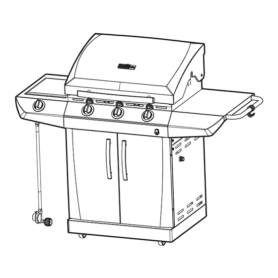
PRODUCT GUIDE
MODEL 463232012
Char-Broil Performance T-36G
IMPORTANT: Fill out the product record information below.
Serial Number
Date Purchased
For support and to register your
grill, please visit us at
www.charbroil.com
If you have questions or need
assistance during assembly,
please call 1-888-430-7870.
Printed in China
See rating label on grill for serial number.
Assembly instructions © 2011
09/22/11 • G519-001-230801

Advertisement

Table of Contents
loading

Summary of Contents for Char-Broil 463232012

  • Page 1 PRODUCT GUIDE MODEL 463232012 Char-Broil Performance T-36G IMPORTANT: Fill out the product record information below. Serial Number See rating label on grill for serial number. Date Purchased For support and to register your grill, please visit us at www.charbroil.com If you have questions or need assistance during assembly, please call 1-888-430-7870.
  • Page 2: Table Of Contents

    TABLE OF CONTENTS DANGER For Your Safety ........2-3 If you smell gas: Use and Care .
  • Page 3 WARNING CAUTION CALIFORNIA PROPOSITION 65 Using pots larger than 6 quarts in capacity could exceed weight limit of the 1. Combustion by-products produced when using this product contain chemicals known to the State of side burner shelf California to cause cancer, birth defects, and other or side shelf, reproductive harm.
  • Page 4: Use And Care

    LP Cylinder USE AND CARE •The LP cylinder used with your grill must meet the following requirements: DANGER •Use LP cylinders only with these required measurements: 12" (30.5cm) (diameter) x 18" (45.7 cm) (tall) with 20 lb. (9 kg.) capacity maximum. •...
  • Page 5: For Your Safety

    LP Cylinder Exchange Connecting Regulator to the LP Cylinder •Many retailers that sell grills offer you the option of replacing 1.LP cylinder must be properly secured onto grill. (Refer to your empty LP cylinder through an exchange service. Use only assembly section.) those reputable exchange companies that inspect, precision fill, 2.Turn all control knobs to the OFF position.
  • Page 6 Leak Testing Valves, Hose and Regulator 1.Turn all grill control knobs to OFF. 2.Be sure regulator is tightly connected to LP cylinder. 3.Completely open LP cylinder valve by turning hand wheel counterclockwise. If you hear a rushing sound, turn gas off immediately.
  • Page 7 Safety Tips WARNING Before opening LP cylinder valve, check the coupling nut for tightness. When grill is not in use, turn off all control knobs and LP cylinder valve. For Safe Use of Your Grill and to Avoid Serious Never move grill while in operation or still hot. Injury: Use long-handled barbecue utensils and oven mitts to avoid •...
  • Page 8 Burner Flame Check Ignitor Lighting (continued) • Remove cooking grates and flame tamers. Light burners, rotate 8. For grills equipped with ELECTRONIC IGNITION at each burner: knobs from HI to LOW. You should see a smaller flame in Repeat steps 4 through 6 to light each burner. LOW position than seen on HI.
  • Page 9: Spider Alert

    3. Remove carryover tubes and burners. CAUTION Detach electrode from burner. NOTE: Removal/Detachment method will depend on the SPIDER ALERT! burner configuration. See different configurations in illustrations below. 5. Carefully lift each burner up and away from valve openings. We suggest three ways to clean the burner tubes. Use the one SPIDER AND WEBS easiest for you.
  • Page 10: Limited Warranty

    LIMITED WARRANTY This warranty only applies to units purchased from an authorized retailer. Manufacturer warrants to the original consumer-purchaser only that this product shall be free from defects in workmanship and materials after correct assembly and under normal and reasonable home use for the periods indicated below beginning on the date of purchase*.
  • Page 11: Parts List

    PARTS LIST Description Description LEFT DOOR, NO HANDLE BOTTOM SHELF TANK SCREW, F/ BOTTOM SHELF HANDLE, F/ DOOR CASTER, LOCKING RIGHT DOOR, NO HANDLE CASTER, FIXED FLAME TAMER COOKING GRATE CART LEFT SIDE PANEL S HOOK GROMMET, F/ REGULATOR HOLE CART RIGHT SIDE PANEL GRATE, F/ SB CART LOWER BACK PANEL...
  • Page 12: Parts Diagram

    PARTS DIAGRAM...
  • Page 13: Assembly

    ASSEMBLY Place bottom shelf upside down. Insert Caster Pin into the caster mounting plate to lock it in place, shown A. Spin the caster clockwise into the threads on the bottom shelf until secure. Remove the Caster Pin and repeat for remaining casters.
  • Page 14 Place lower back panel between side panels at rear of bottom shelf. Secure lower back panel to side panels using four 1/4-20x1/2” screws, 7mm lock washers, and 7mm flat washers on each side. Lower back panel 1/4-20x1/2” screw 7mm lock washer 7mm flat washer This step requires two people to lift and position grill head...
  • Page 15 On back of grill, place upper back panel between side panels and above lower back panel. Secure upper back panel, in lower holes, using one 1/4-20x1½” screw, 7mm lock washer, and 7mm flat washer on each side. Do not fully tighten screws until side shelf installation is complete in later steps. Upper back panel 1/4-20x1½”...
  • Page 16 Hang the four S hooks on towel bar. Attach towel bar to right side shelf using two 1/4-20x3/4” screws, 7mm lock washers and 7mm flat washers, shown A. Insert flange on right side shelf into side shelf brackets on side of firebox, shown B.
  • Page 17 Insert flange on left sideburner shelf into side shelf brackets on side of firebox. Attach left sideburner shelf using three 1/4-20x3/4” screws, 7mm lock washers, 7mm flat washers, 1/4” nuts, shown A. screw, 7mm lock washer, and 7mm Attach rear of shelf using one 1/4-20x1½”...
  • Page 18 First, remove the two screws and lock washers factory attached to the sideburner valve bracket. Position sideburner valve bracket beneath sideburner shelf fascia so that valve stem comes through larger center hole in fascia. Align the holes on valve bracket with left and right holes on fascia. Secure using lock washers and screws that were removed from bracket. Next, place sideburner bezel over valve stem on front side of fascia.
  • Page 19 Insert sideburner burner into left shelf. The stud on bottom of burner fits into rear small hole in sideburner drip pan on shelf, shown A. Secure burner to sideburner drip pan with one Wing nut, shown B. Make sure burner tube engages sideburner valve, shown C.
  • Page 20 Insert front brace under control panel and between cart side panels. Make sure door hinge pins are on the top side and facing the front. Secure using two 1/4-20x1½” screws, 7mm lock washers, and 7mm flat washers on each side. NOTE: MAKE SURE THAT THE FRONT BRACE IS MOUNTED IN THE MOST DOWNWARD POSITION WHEN ASSEMBLED TO CART.
  • Page 21 Release the cap and nut from electronic ignition module. Attach electronic ignition module to the cart right side panel with the nut and cap, shown A. Connect each of the wires from the main burner electrodes, and sideburner electrode into the back of the Electronic Ignition Module.
  • Page 22 Install flame tamers by sliding one end of each flame tamer into slots at front of firebox and resting opposite end on pins in back of firebox. Note: Some parts omitted for clarity of illustration Front of firebox Flame tamers Back of firebox Place cooking grates onto the firebox as shown.
  • Page 23 On back of grill, slide grease tray into opening in upper back panel. CAUTION Failure to install grease tray will cause hot grease to drip from bottom of grill with risk of fire or property damage. Grease tray Unscrew electronic ignition cap on cart right side panel.
  • Page 24 LP CYLINDER IS SOLD SEPARATELY. Fill and leak check the cylinder before attaching to grill and regulator (see Use & Care section). Once cylinder has been filled and leak checked, place cylinder into hole in bottom shelf. Make sure cylinder valve is facing front of grill.
  • Page 25: Troubleshooting

    DANGER: If a gas leak cannot be stopped, or a fire occurs due to gas leakage, call the fire department. Emergencies Possible Cause Prevention/Solution Gas leaking from • Damaged hose. • Turn off gas at LP cylinder or at source on natural gas systems. If cracked/cut/burned anything but burned, replace valve/hose/regulator.
  • Page 26 Troubleshooting (continued) Problem Possible Cause Prevention/Solution Burner(s) will not light ELECTRONIC IGNITION: using ignitor. • No spark, no ignition noise. • See Section I of Electronic Ignition System. (See Electronic Ignition Troubleshooting also) • No spark, some ignition noise. • See Section II of Electronic Ignition System. •...
  • Page 27 Troubleshooting - Electronic Ignition Problem (Ignition) Possible Cause Check Procedure Prevention/Solution SECTION I No sparks appear at • Battery not installed • Check battery orientation. • Install battery (make sure that “+” and “–” any electrodes when properly. connectors are oriented correctly, with “+” end up Electronic Ignition Button and “–”...
  • Page 28 NOTES...
  • Page 29 NOTES...
  • Page 30 NOTES...

This manual is also suitable for:

T-36gPerformance t-36g 463232012

Table of Contents